Forum sponsored by:

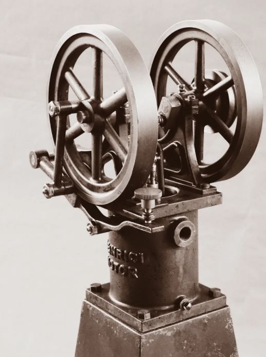
Heinrici without Castings
| JasonB | 15/01/2021 16:22:03 |
 25215 forum posts 3105 photos 1 articles | The two cast iron flywheels turned up today along with some barstock for other parts, I can see cast iron swarf featuring heavily in my upcoming workshop activity
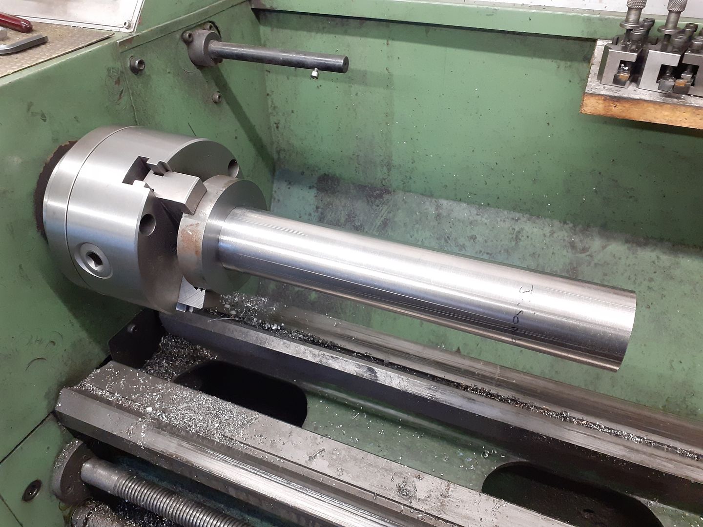
Made a start on one of them getting the turning done prior to going on the CNC, I used the crank to gauge a nice firm push fit of the bore which should eliminate any tendency to wobble.
As Colin was asking about speeds for turning cast iron the other day I thought I would film the facing off of the excess material. 140mm dia, 425rpm, 0.75mm DOC, 0.075mm/rev feed. Quite reasonable chips and minimal dust, I find the 280 prefers to run a bit on the fast side with a slightly lighter cut rather than a slow backgear speed and deeper cut but the 0.75mm or 30thou DOC soon got rid of the waste material. |
| Ron Laden | 16/01/2021 07:49:19 |
 2320 forum posts 452 photos | Good chips their Jason and a nice finish, out of interest what insert type did you use, it looks uncoated but maybe not..? Ron |
| JasonB | 16/01/2021 13:13:01 |
25215 forum posts 3105 photos 1 articles | Its ALTiN coated, similar to the grey coating you get on some milling cutters. Bit of blurb about it here from the Kennametal website. I did not buy them specifically with that coating it's just that the size and price was right.
|
| JasonB | 17/01/2021 16:43:36 |
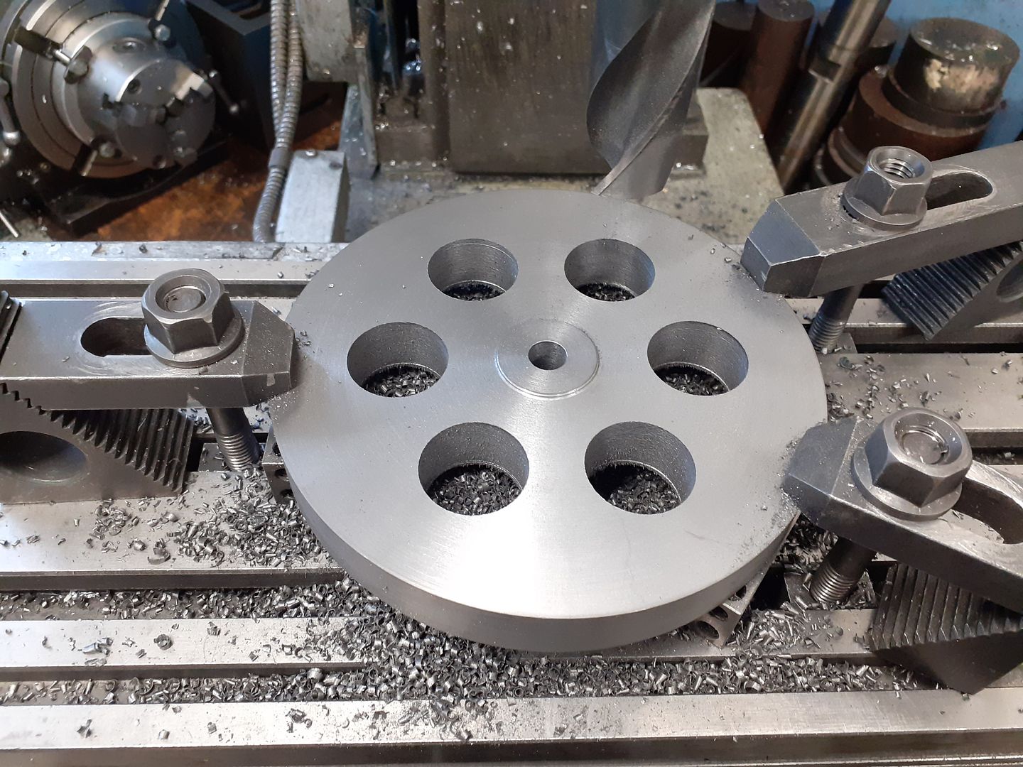
25215 forum posts 3105 photos 1 articles | After turning the second black I decided drill six 1" holes to remove some of the initial waste material as it's a bit more fun than watching the CNC do it with the added bonus that the swarf can drop down rather than need clearing out of deep pockets. While set up like this I also held a scriber point in the chuck and marked the edge of the disc so I could get in the correct position on the other mill.
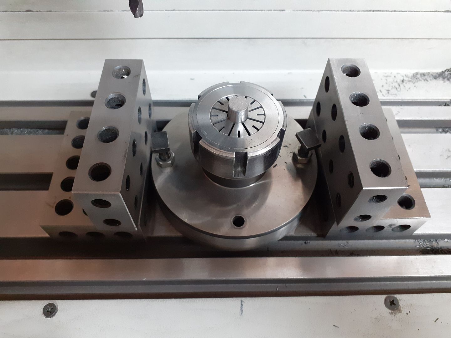
As I had two flywheels to do and they would need setting up twice so that each side could be done I put a piece of the crankshaft material in a flange mount ER32 collet and clocked that in to 0,0 so the parts would always be centred. 1,2,3 and 20, 40, 80 blocks packed the work up to just clear the top of the collet nut.
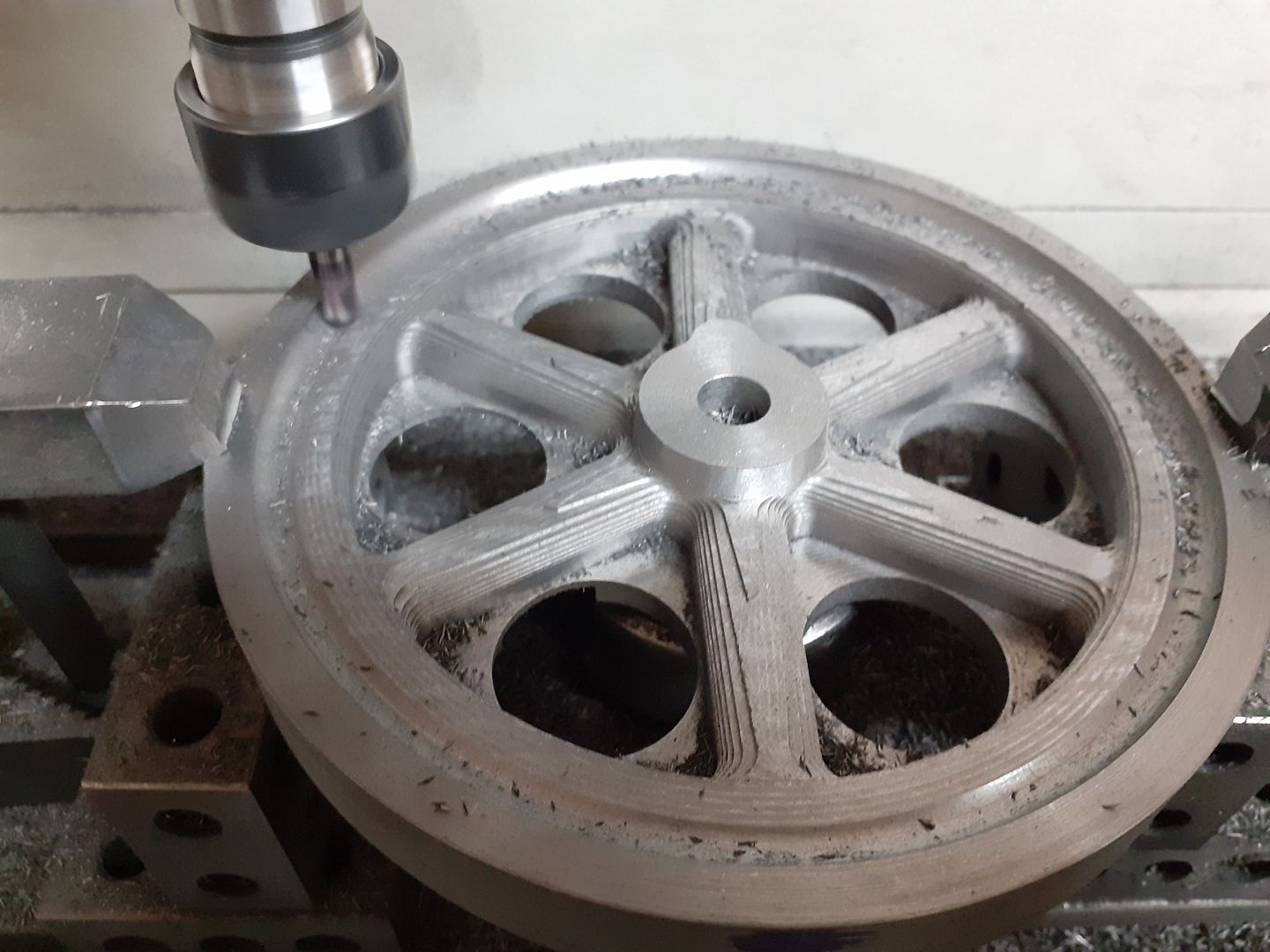
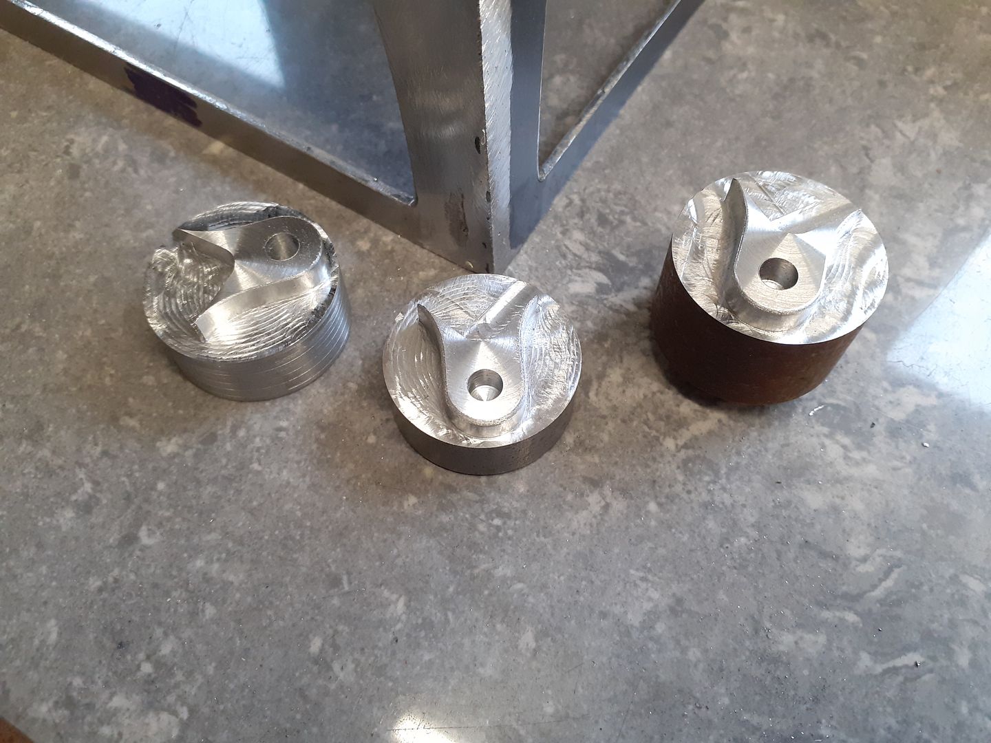
It was then just a case of placing a flywheel on the pin, rotating until the mark lined up with a pointer in the chuck and clamping down tight. The basic shape was roughed out with an adaptive path using a 6nn 3-flute cutter at 4500rpm, 300mm/min feed, 5mm vertical DOC with 1mm stepover to leave it looking like this
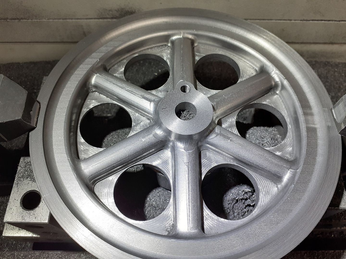
I've actually just started the finishing "scallop" cut in the above photo using a 6mm 4-flute ball ended cutter at 4500rpm, 500mm/min feed and a stepover of 0.25mm which slowly worked its way around the rim and then down around each spoke to leave a finished half looking like this.
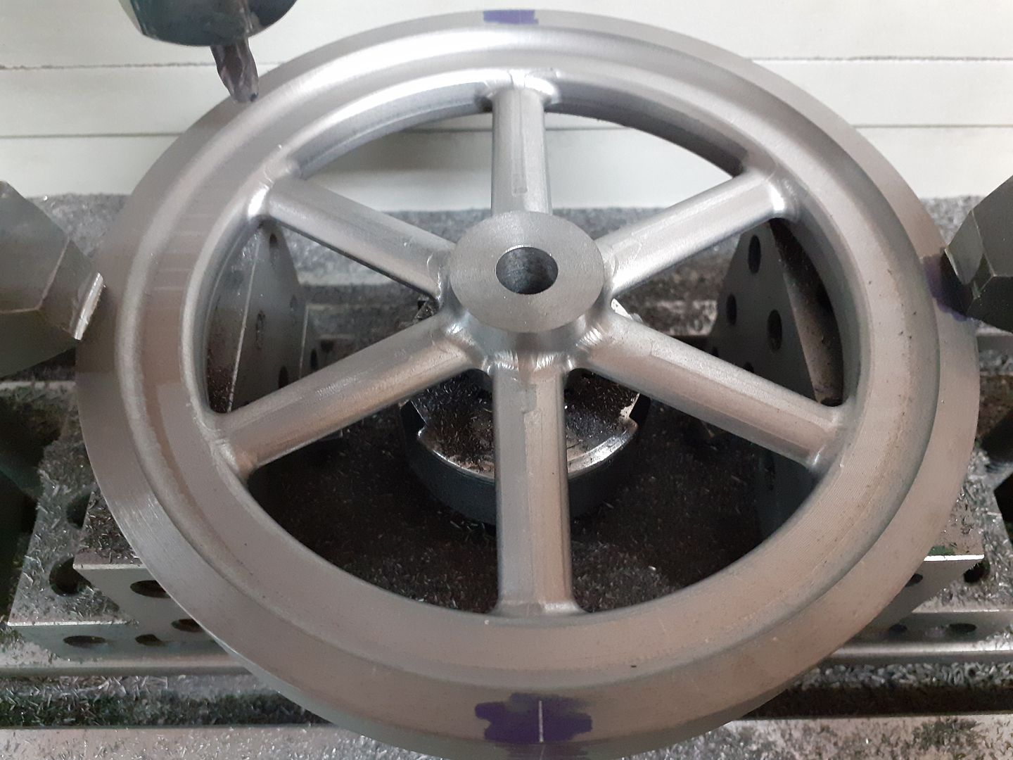
It was then just a case of flipping the part over and running similar cuts for the other side though the boss is round on the inside where as the outside had the boss for the crank pin.
The few odd ridges and steps look a lot worse than they feel and were quickly removed with needle files and a bit of Emery. I also got round to setting up an air lower for the second side and wish I had done it sooner as I was able to leave the machine to it's own devices rather than having to keep clearing swarf like I did on the first side during the roughing cuts, not so bad on the finish cuts as very little is being removed. Will show some photos of this in the Further Adventures thread at some time. |
| JasonB | 19/01/2021 13:28:18 |
25215 forum posts 3105 photos 1 articles | Video of theflywheel being cut in this post |
| JasonB | 24/01/2021 19:15:23 |
25215 forum posts 3105 photos 1 articles | Well I've checked and double checked my setups and think it's safe for me to post some more photos of progress and I do hope the weekends forum activity won't put others off posting about what they have been up to in there workshops. First a pic of the flange that will be soldered to the hot cap being counterbored using the 45mm stainless tube to gauge final fit, not easy when the tube is not perfectly round or 45mm dia.
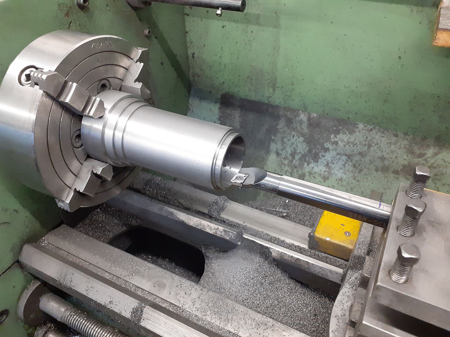
The power cylinder was cut from some 65mm dia cast iron bar. Regarding the recent thread about boring bars this hole is 110mm long, 42mm finish dia and was cut with a 16mm insert boring bar. Started with blacksmith drills upto 1" then to 41mm with a CCMT insert 0.75mm DOC, 600rpm. Then for the last few cuts swapped to a CCGT with two cuts of 0.2mm and one of 0.1mm DOC all at 250rpm and ended up with less than 0.025mm ( 1 thou ) taper which was soon taken care of by selective use of a 3 stone hone.
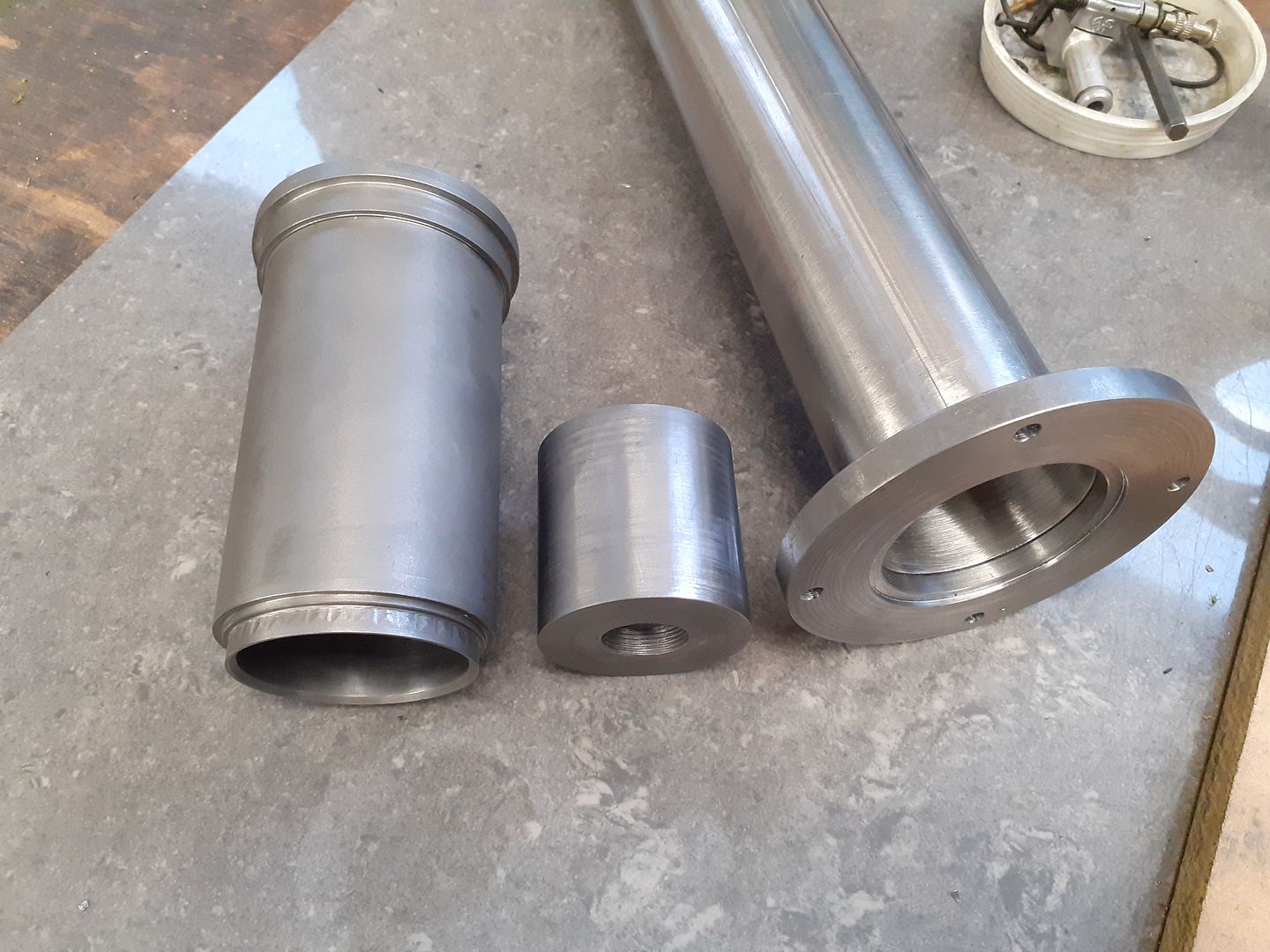
And finally the near complete flange which just wants squaring off a bit, completed cylinder and in the middle the 42mm dia x 42mm long CI piston which as a 1.25mm wall and a M18 x 1 thread in the 6mm thick botton to more closely resemble an original rather than the CSK screws shown on the drawings I'm using as a basis for the engine.
|
| JasonB | 27/01/2021 17:00:30 |
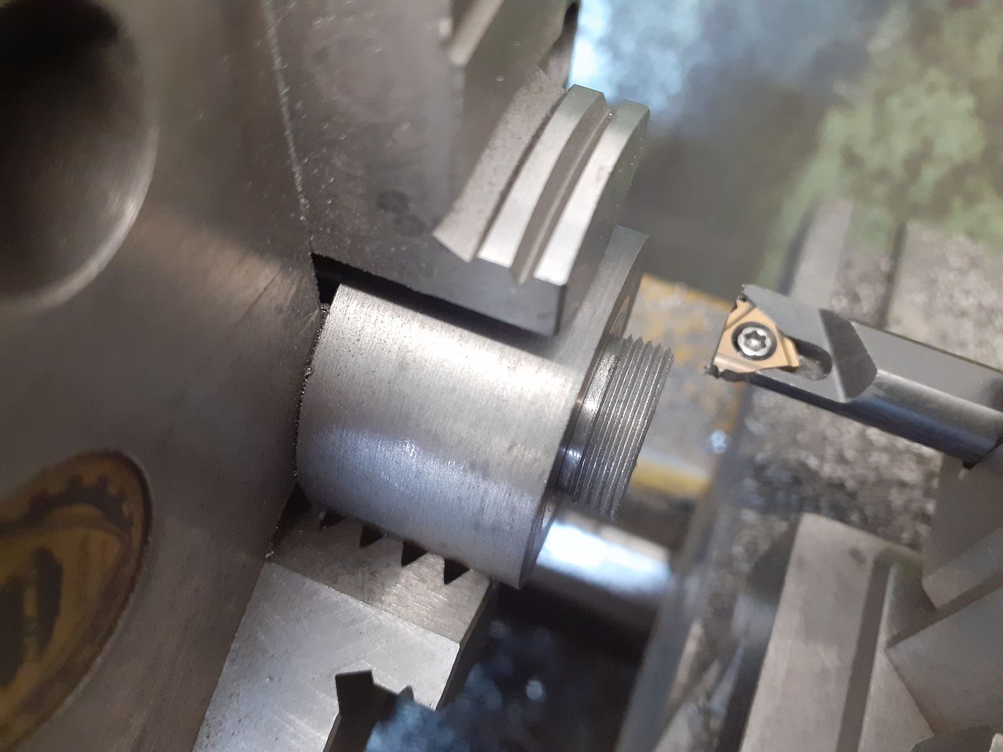
25215 forum posts 3105 photos 1 articles | The next part on the list was the yoke that fits inside the piston, a spigot was turned on the end and then threaded M18 x 1 running in reverse so the tool moves away from the face.
Then over to the mill to machine most of it away but leaving a flange at the bottom
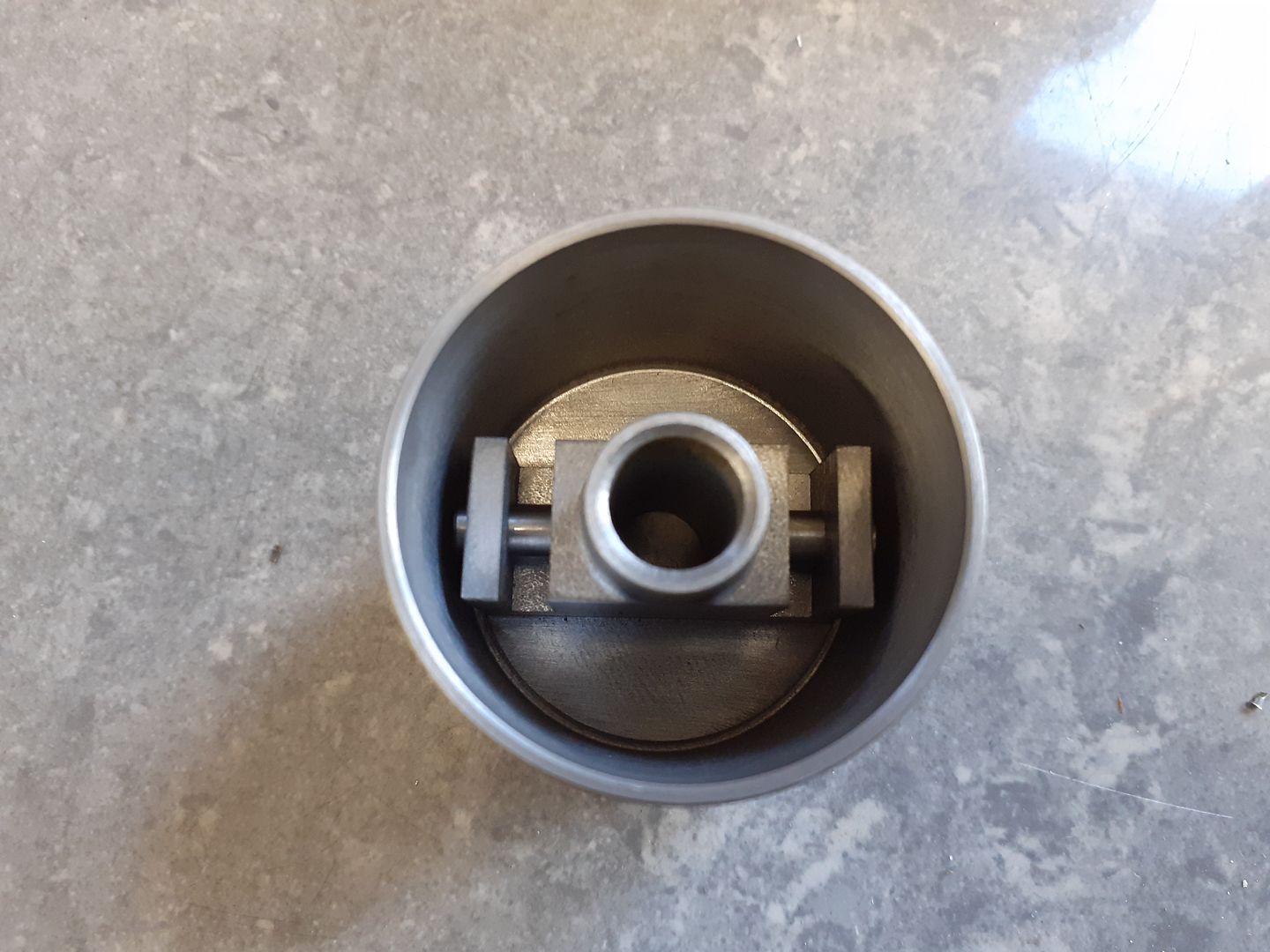
A couple of 4mm wide slots were cut for the ends of the tuning fork shaped conrod and cross drilled for pins, picture of it assembled inside the piston
And another without piston but showing the thin walled brass tube that forms the displacer's piston rod passing through it.
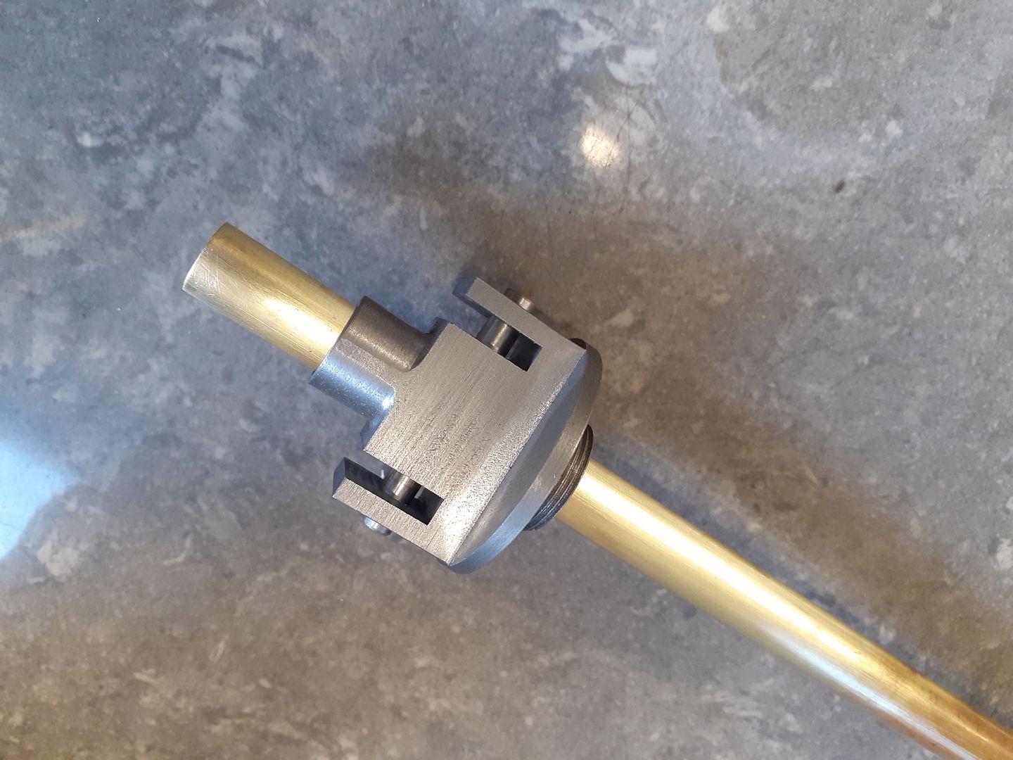
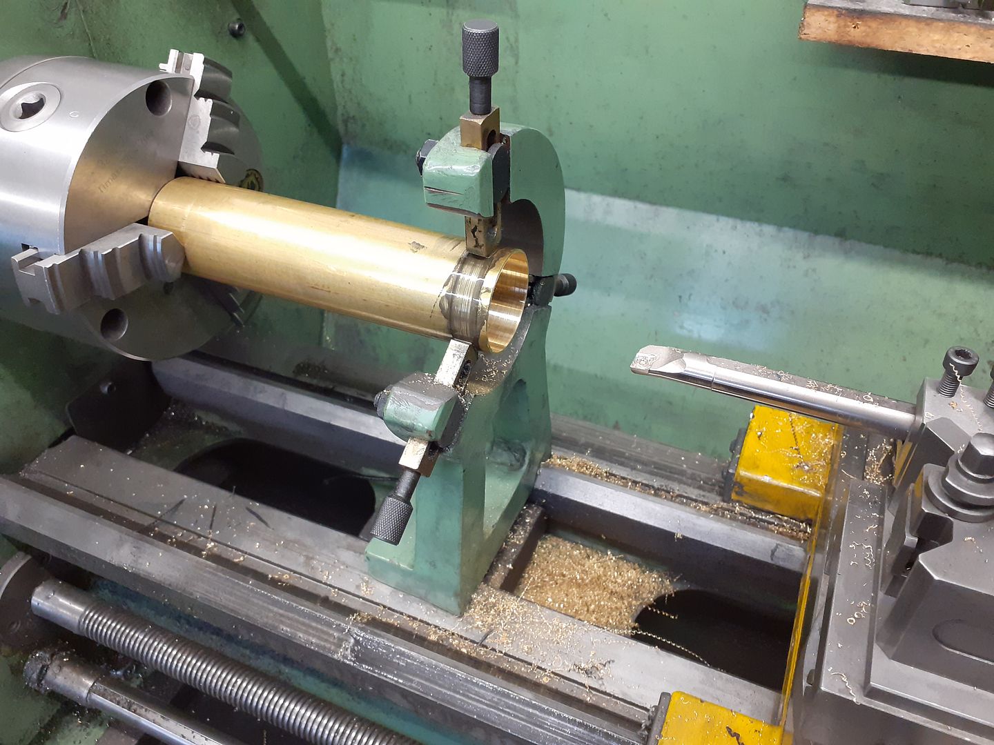
Bearing in mind the weight issue that Jo mentioned on her engine while I was set up for squaring the ends of the brass tube for the displacer I thought I would thin the 1.25mm wall down to 0.9mm to save a bit of weight. I knocked up a bung to go in the end of the tube so that the chuck would not distort the tube which also allowed it to be tightened up well so no risk of the tube walking out of the chuck
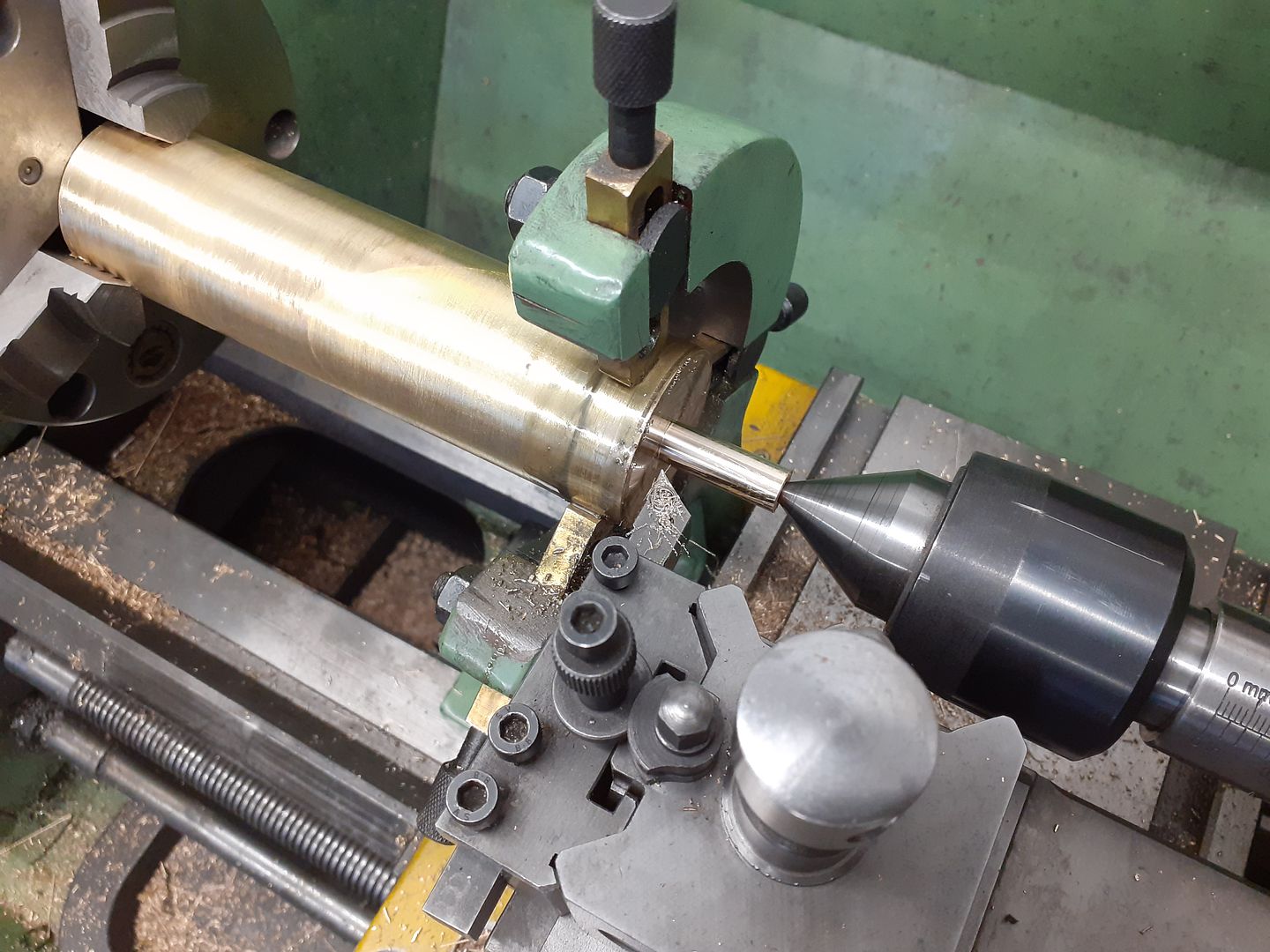
After silver soldering the endplates and a spigot into place it was back in the lathe to drill and tap the spigot. I then added ctr support while the spigot was turned down to finish size so it was a firm fit in the thin wall brass tube.
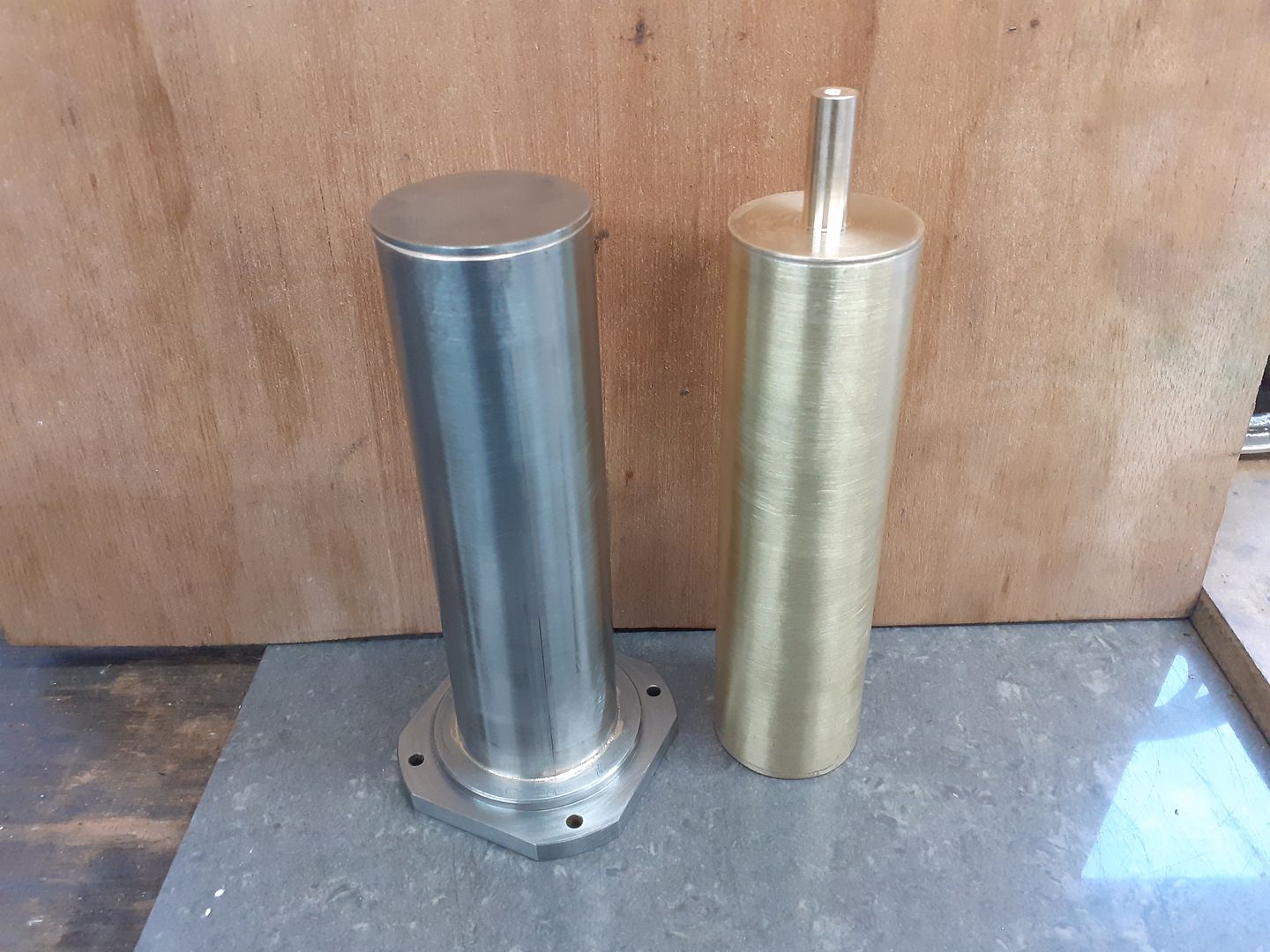
Finally a shot of the finished displacer alongside the stainless steel hot cap with silver soldered end and mounting flange
|
| JasonB | 04/02/2021 13:11:04 |
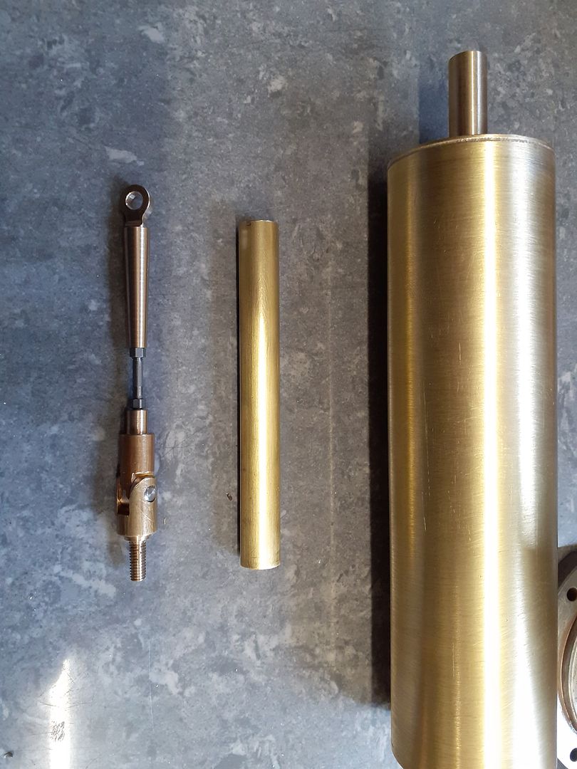
25215 forum posts 3105 photos 1 articles | Next job on the list was to make the displacer rod which is made up on several pieces so that it does not tighten up as the rocking lever follows an arc, The drawings show the 2mm steel rod silver soldered into the two brass parts but I decided to allow for some adjustment if needed so went with a rod threaded M2.5 each end and some lock nuts. I also cut the thin wall brass guide tube to length
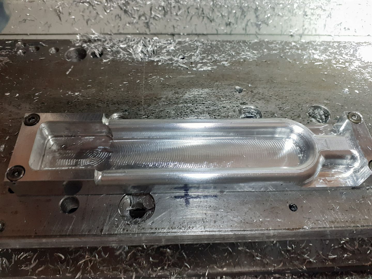
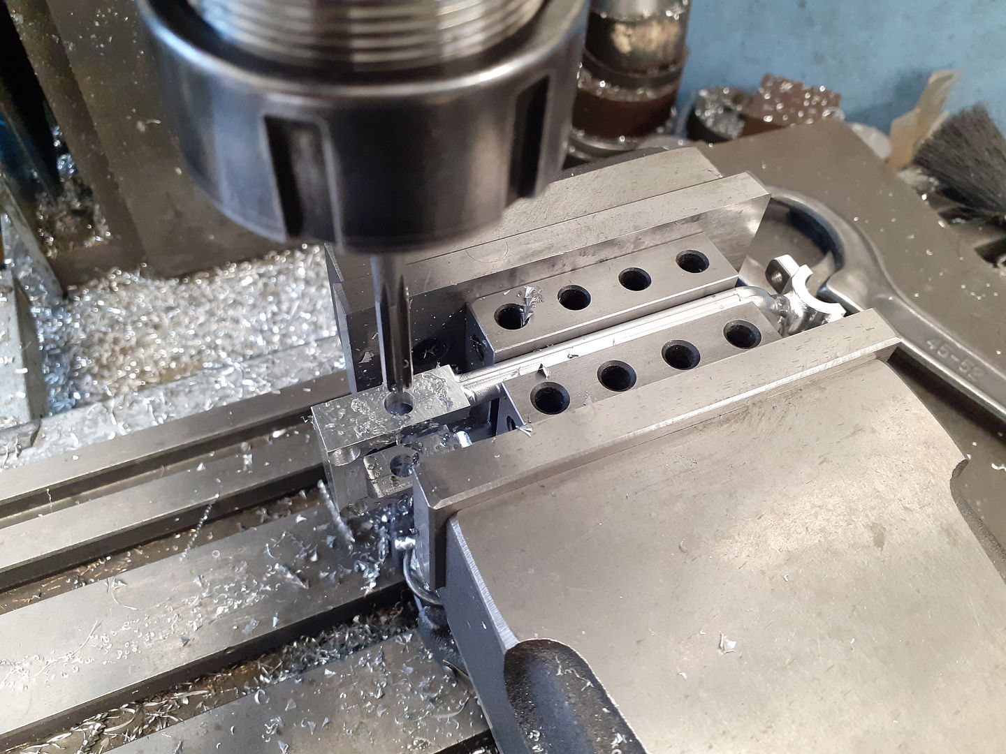
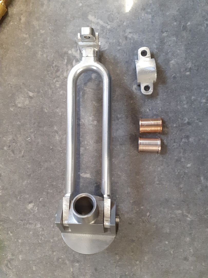
The "tuning fork" conrod would have wasted a lot of metal if cut from one piece so I decided to do it in two. Firstly the actual fork was cut on the CNC holding it by two extra 6mm pieces left at the ends which made it easy to flip over and run the other side.
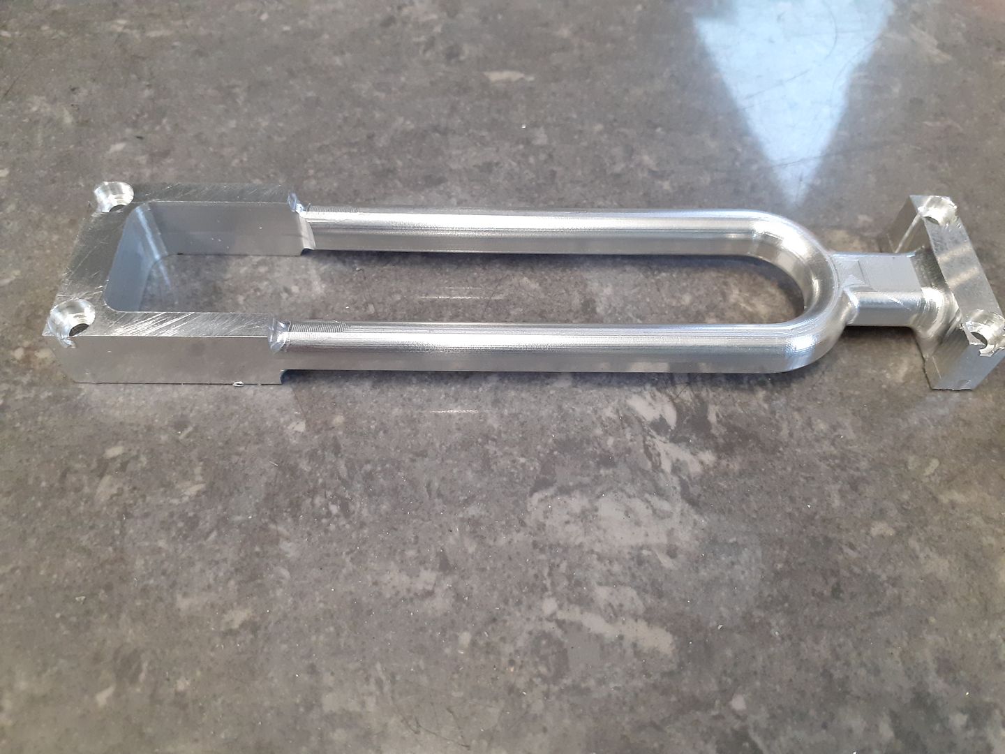
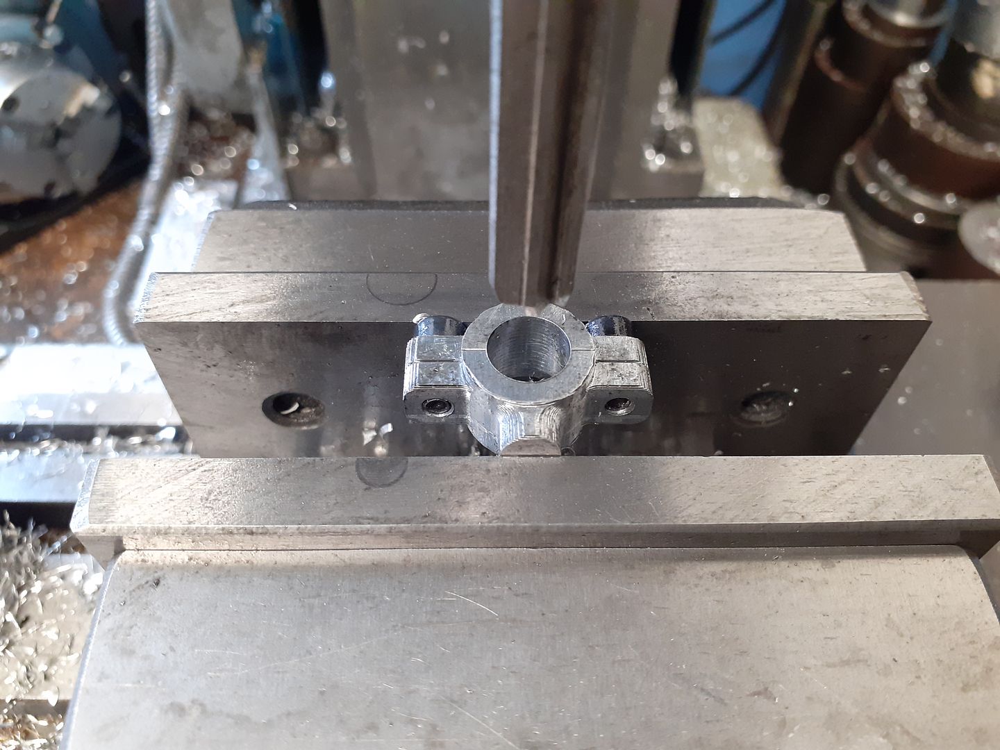
The big end halves were also done on the CNC before reaming in the manual mill. I then managed to get two M2 counterbored holes in the bottom of the bore so that I could screw it to the top of the fork with a bit of JB Weld for good measure.
The last thing to do was ream the small end before cutting off the holding material and rounding over the ends
As with all the other pivoting or rotating holes through the aluminium bushes were fitter, in the case of the small ends there were Loctited into place and a traditional split bearing used for the big end.
Edited By JasonB on 04/02/2021 13:15:01 |
| Ron Laden | 04/02/2021 14:08:05 |
2320 forum posts 452 photos | Wow Jason, that seems to have come on a long way in a short period of time and a test run also. It runs a treat you must be pleased with it, I was surprised how long it ran on for after the heat source was removed I was expecting it to run for a little while but not as much as it did. Really very nice indeed. Ron |
| Roderick Jenkins | 04/02/2021 14:34:24 |
 2376 forum posts 800 photos | Posted by Ron Laden on 04/02/2021 14:08:05:
Wow Jason, that seems to have come on a long way in a short period of time and a test run also. It runs a treat you must be pleased with it, I was surprised how long it ran on for after the heat source was removed I was expecting it to run for a little while but not as much as it did. He forgot to turn the electric motor off Seriously though, amazing work (as always). Stay well, Rod |
| JasonB | 04/02/2021 19:34:43 |
25215 forum posts 3105 photos 1 articles | Shush Rod, your not meant to mention that Ron, it did all seem to come together quite quickly at the end. There are actually not that many parts to it and the majority of the work was in fabricating or cutting from solid to get the "castings". Had it been done from a casting set it probably would only have taken 2-3 weeks instead of just over 6weeks from when I cut the first metal. I still have the base to make and various fixings etc as well as deciding whether to go with spirit fired or put a small camping stove burner under it. |
| JasonB | 07/02/2021 16:26:14 |
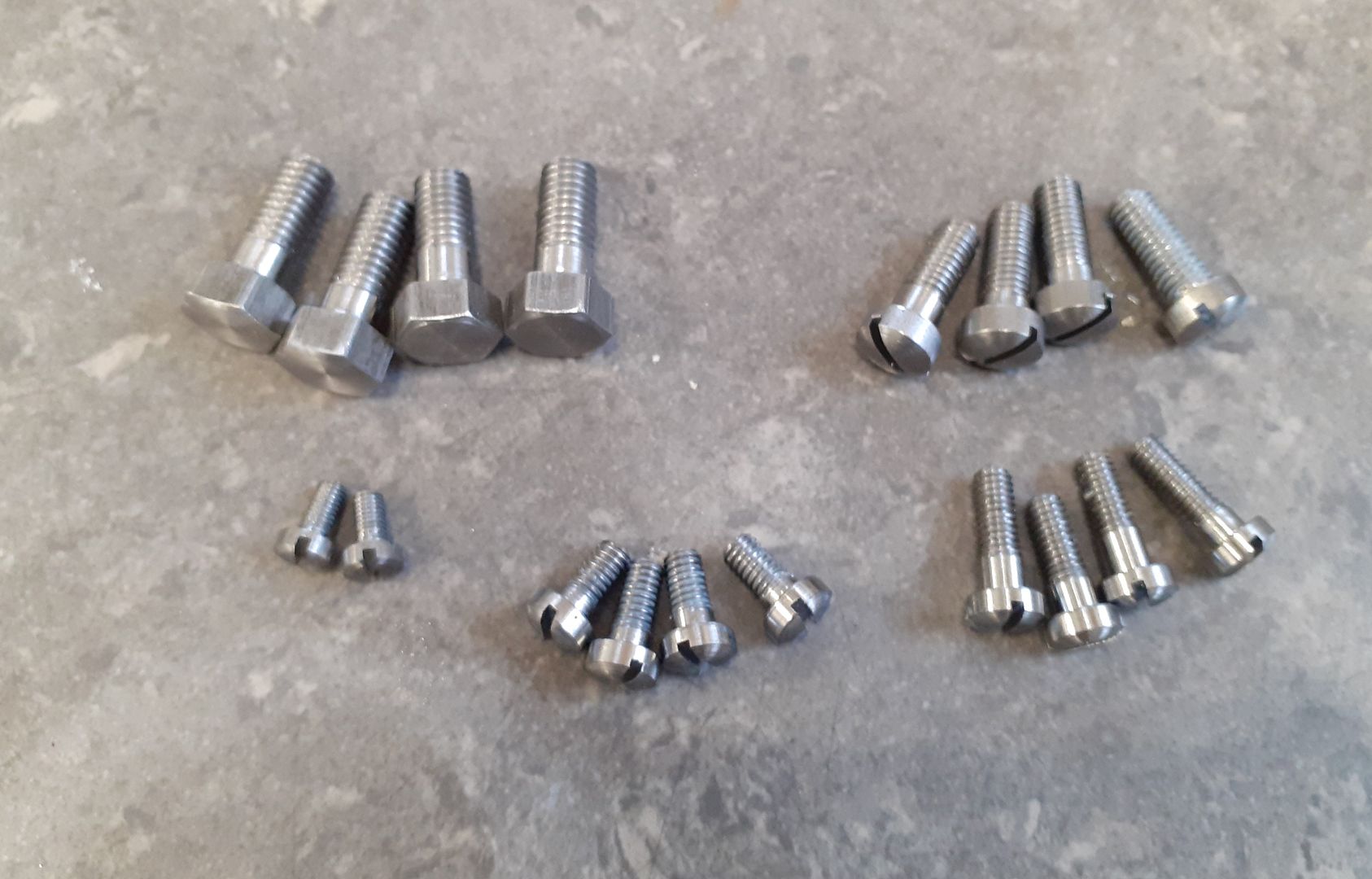
25215 forum posts 3105 photos 1 articles | With two lots of Cyclocross streaming this weekend there was not so much progress but I did get the screws made for the engine ranging from M3 to M6, just a couple of nut still to do.
|
| JasonB | 14/02/2021 16:53:42 |
25215 forum posts 3105 photos 1 articles | Now that the engine is know to work my thoughts turned to the stand. I was not so keen on the screwed together from plate and angle that was shown on the drawings that I have based mine on so decided to weld one up to look more like a cast base but go my own way as I'm not keen on the "1/4 pipe" profile around the bottom of the originals. Four pieces of 2mm mild steel were cut out with an thin disc in the angle grinder and then trimmed to size on the manual lathe. I then used the CNC to cut out the arch shape in each leaving 3 tabs to stop the waste moving about. There was a small amount of burring as the cutter ramped into the cut but OK once in had settled down into the cut. 4mm 3-flute carbide at 5000rpm and 300mm/min feed. I silver soldered on a stub of 22mm copper tube for the chimney before clamping the plates to a piece of 3 x 4 angle and tack welding them. My welding is nothing to get excited about but OK for this sort of thing.
Then the rest of the joint was run.
I added a top plate from 2.5mm thick material and then gave the welds an initial clean up with the grinder.
Next job is to add some feet and cut a hole in the top for the hot cap to pass through. |
| JasonB | 16/02/2021 19:04:20 |
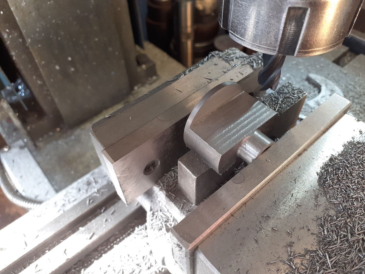
25215 forum posts 3105 photos 1 articles | I used up some bar ends of 30mm steel to make the feet using the CNC to drill profile and round over the top outer edge before cutting off and silver soldering to the base.
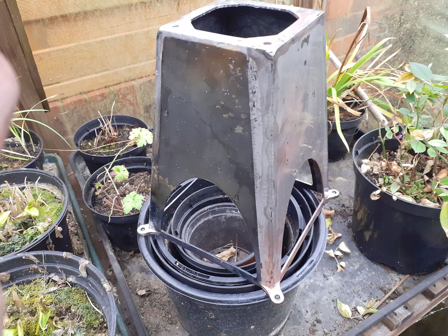
Ron asked about pickling black mild steel (hot rolled) to remove the mill scale so took this photo. The sheet used for 3 of the 4 sides had a very smooth scale on them which a flap disc in the 4.5" grinder just skidded off except close to the welds so after the silver soldering I filled a shallow tray with brick cleaner and left to marinade for 40mins. You can see that the side to the right is now bright steel with the tide mark wrapping part way up the left side. Excuse the plants but I normally do it outside but it was raining so took cover in the greenhouse.
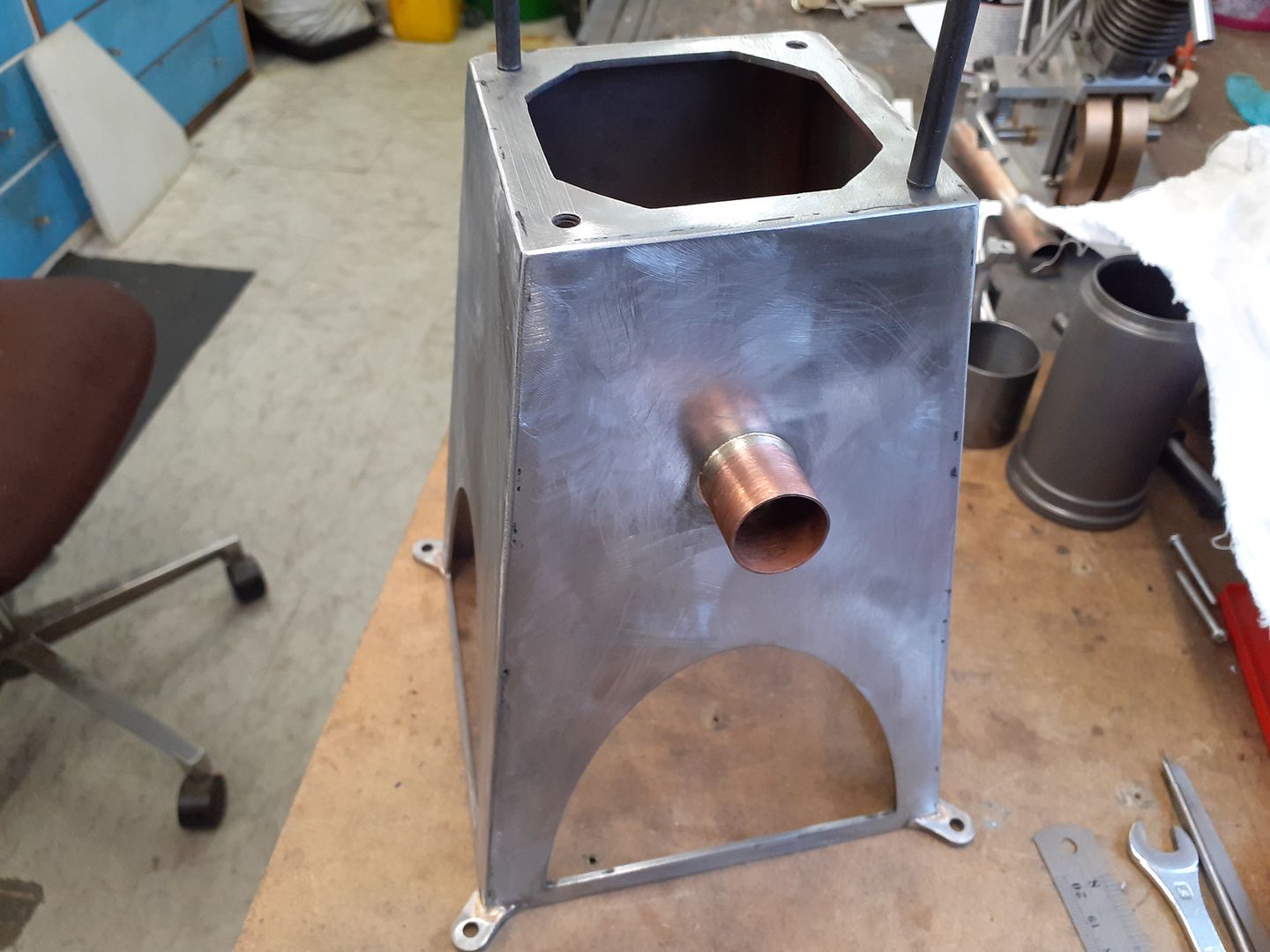
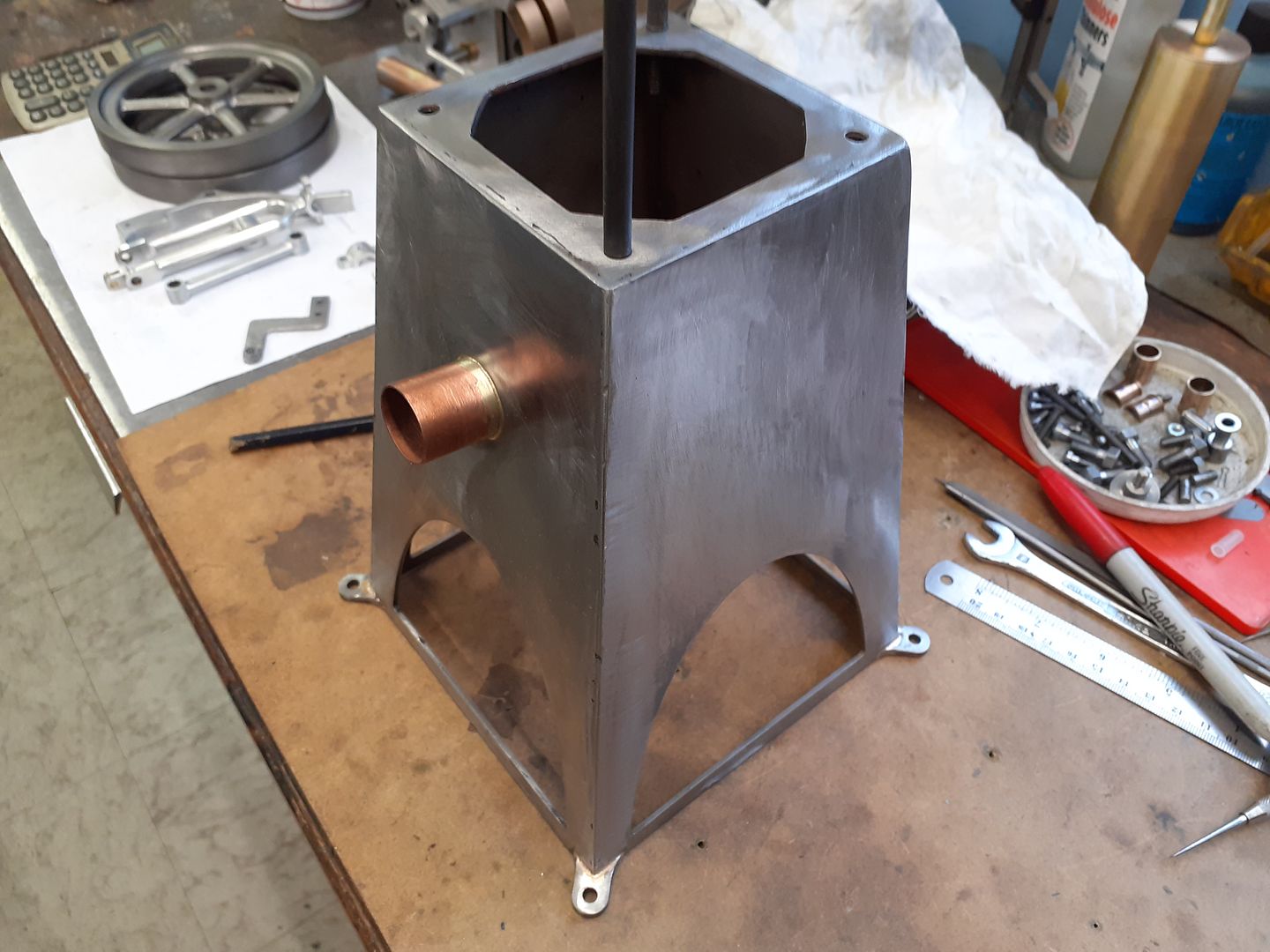
The other two sides were treated the same which removed all the scale and any soldering flux and then a final fine flap disc to key the surface for paint, you can also see the hole to clear the hot cap flange has been milled into the top plate.
I've also test run it on the base using one of the cheap portable camping stove burners and it romps away with the flame set right at it's lowest |
| Ron Laden | 17/02/2021 06:46:28 |
2320 forum posts 452 photos | Morning Jason The base looks great I like the shape and the look you have achieved there. I am amazed at how just 40 minutes in the Brickclean de-scales the steel to a bright finish I would never have imagined that until you told me about it. Ron |
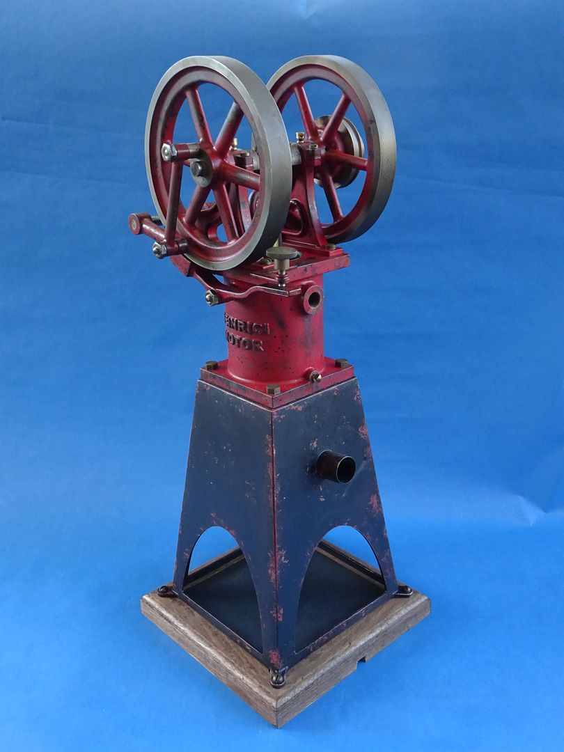
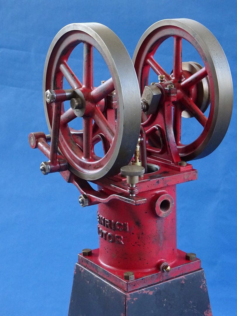
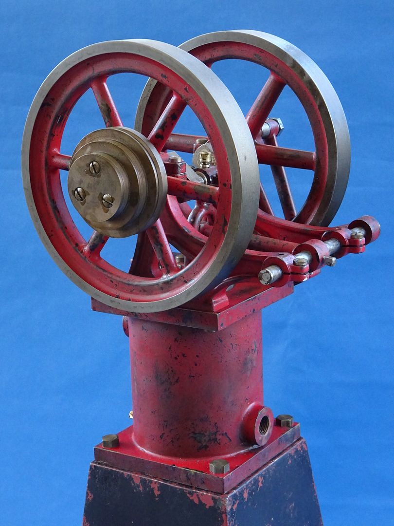
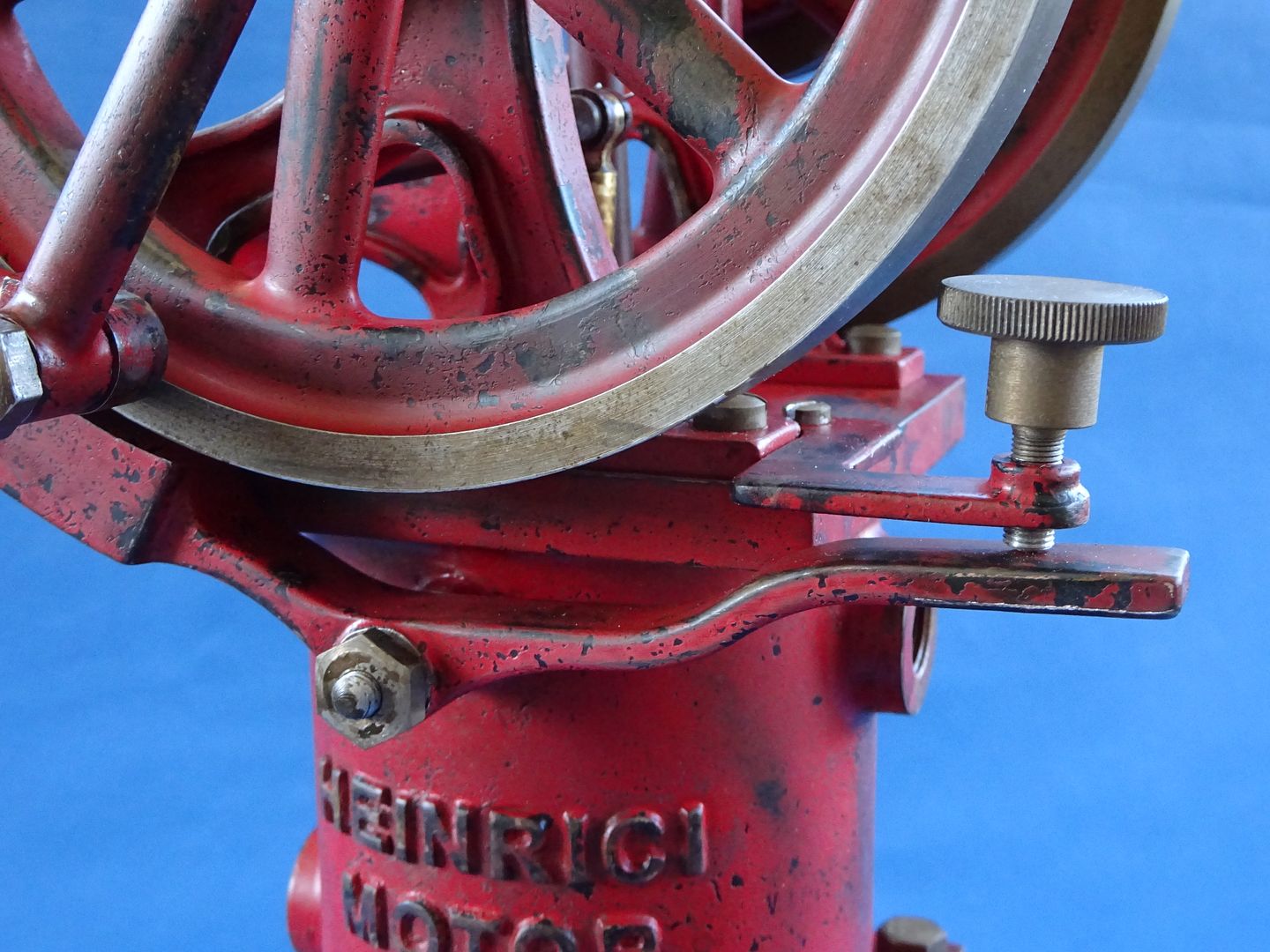
| JasonB | 26/02/2021 14:03:18 |
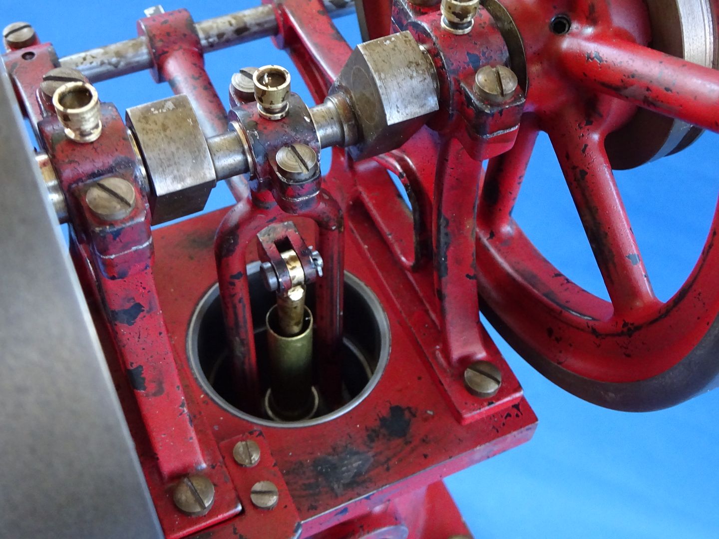
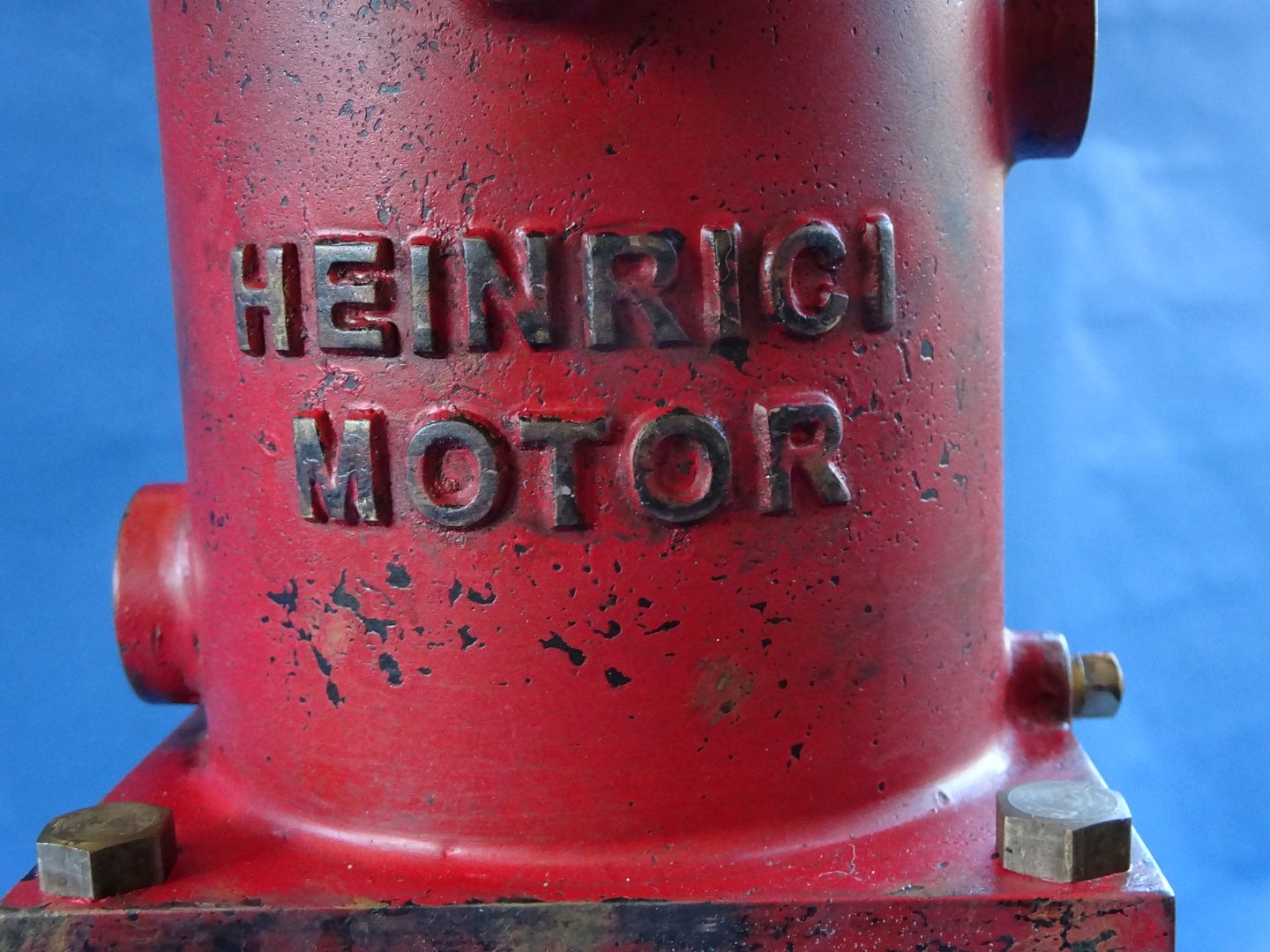
25215 forum posts 3105 photos 1 articles | Well it's taken a bit longer to paint than usual as I went for something a bit different (no I have not deviated from Red Ramon) For some time I have toyed with the idea of painting an engine in something other than the usual bright new paintwork and bright though not blinged up bare metal, I quite liked the patinated bronze of Ralf's original but that was not the materials originally used so I got busy with my paint brushed and the airbrush as well as the usual spray cans.
I made up a simple base and milled a hole in it for a cheap camping stove burner that will run the engine at it's lowest setting and it will carry on running for quite a while once the head source is turned off. I have run it for several times for about 15mins each time and the jacket does not get particularly hot as you can easily hold your hand on it and that is without any cooling water plumbed up. Edited By JasonB on 26/02/2021 14:03:54 |
| Roderick Jenkins | 26/02/2021 18:56:57 |
2376 forum posts 800 photos | That really is very effective. Most impressive, thanks for sharing the journey with us. Rod |
| Ron Laden | 26/02/2021 20:24:38 |
2320 forum posts 452 photos | That really is superb Jason, that looks to be very well used and years old and none of it looks as if it has been added, it looks like genuine age and general wear and tear from years of use. For me what makes it work so well is that you have covered every part from top to bottom and not just odd bits here and there. Can I ask how you did the chipped paint work and also the discoloured bare steel its so realistic. Great stuff Jason, some excellent work there. Ron
|
| DiogenesII | 26/02/2021 21:09:57 |
| 859 forum posts 268 photos |
|
| Craig Brown | 27/02/2021 03:12:14 |
| 110 forum posts 57 photos | Top work on the finishing there you really have aged it nicely. If you would have said it was an original engine I wouldn't even bat an eyelid |
 Good service from M-machine as only ordered yesterday.
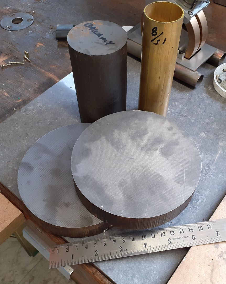


.jpg)
.jpg)
.jpg)

Please login to post a reply.
Magazine Locator
Want the latest issue of Model Engineer or Model Engineers' Workshop? Use our magazine locator links to find your nearest stockist!
Sign up to our Newsletter
Sign up to our newsletter and get a free digital issue.
You can unsubscribe at anytime. View our privacy policy at www.mortons.co.uk/privacy
Latest Forum Posts
- hemingway ball turner
04/07/2025 14:40:26 - *Oct 2023: FORUM MIGRATION TIMELINE*
05/10/2023 07:57:11 - Making ER11 collet chuck
05/10/2023 07:56:24 - What did you do today? 2023
05/10/2023 07:25:01 - Orrery
05/10/2023 06:00:41 - Wera hand-tools
05/10/2023 05:47:07 - New member
05/10/2023 04:40:11 - Problems with external pot on at1 vfd
05/10/2023 00:06:32 - Drain plug
04/10/2023 23:36:17 - digi phase converter for 10 machines.....
04/10/2023 23:13:48 - More Latest Posts...
- View All Topics
Support Our Partners


Shopping Partners
Subscription Offer

Latest "For Sale" Ads
- Reeves** - Rebuilt Royal Scot by Martin Evans
by John Broughton
£300.00 - BRITANNIA 5" GAUGE James Perrier
by Jon Seabright 1
£2,500.00 - Drill Grinder - for restoration
by Nigel Graham 2
£0.00 - WARCO WM18 MILLING MACHINE
by Alex Chudley
£1,200.00 - MYFORD SUPER 7 LATHE
by Alex Chudley
£2,000.00 - More "For Sale" Ads...
Latest "Wanted" Ads
- D1-3 backplate
by Michael Horley
Price Not Specified - fixed steady for a Colchester bantam mark1 800
by George Jervis
Price Not Specified - lbsc pansy
by JACK SIDEBOTHAM
Price Not Specified - Pratt Burnerd multifit chuck key.
by Tim Riome
Price Not Specified - BANDSAW BLADE WELDER
by HUGH
Price Not Specified - More "Wanted" Ads...
Get In Touch!
Do you want to contact the Model Engineer and Model Engineers' Workshop team?
You can contact us by phone, mail or email about the magazines including becoming a contributor, submitting reader's letters or making queries about articles. You can also get in touch about this website, advertising or other general issues.
Click THIS LINK for full contact details.
For subscription issues please see THIS LINK.
Digital Back Issues


Donate

 Register
 Log-in
Model Engineer Magazine
- Percival Marshall
- M.E. History
- LittleLEC
- M.E. Clock

ME Workshop
- An Adcock
- & Shipley
- Horizontal
- Mill

Subscribe Now
- Great savings
- Delivered to your door

Pre-order your copy!
- Delivered to your doorstep!
- Free UK delivery!
All Forum Topics > Miscellaneous models > Heinrici without Castings