Forum sponsored by:

Stuart Twin Victoria (Princess Royal) Mill Engine
| Dr_GMJN | 11/11/2020 08:06:40 |
 1602 forum posts | Posted by JasonB on 11/11/2020 07:05:00:
By soldering 3 pieces of the 1/2" square stock together that will give you a distance from ctr of hole to "bottom" of the outer two pieces of 3/4" which is the required distance. Note that you may not quite have 0.500" stock but the 1/2" is not the critical size its ctr line to the notch that sits on the frame that matters. This notch would be best machined after JBWelding it together as you can't be accurate glueing to the cast surface. Another option would be to do them on the cross slide with a between ctrs boring bar, a simple block to bring the blank to height and screw them to would make it fairly simple but I think the soldered method will be quicker.
Edited By JasonB on 11/11/2020 07:49:00
Thanks Jason. Silver solder? If so I’ll need to get some (and a new gas bottle). What is a good between centres boring bar to get? I might need one for the cylinders.
|
| Ramon Wilson | 11/11/2020 08:40:15 |
 1655 forum posts 617 photos | A simple pin set on centre line of the arc and another in the cylinder wall will locate the feet accurately enough while the JB sets, though I was underr the impression the mating area was going to be machined too. Yes another way this op can be done, but as Jason says it would be best to machine the lower surfaces after bonding - done with the cylinder held on a mandrel the dimension would be both identical over both parts and importantly parallel with the cylinder bore too You can make a simple 'tween centres boring bar of any size you want to suit the job. I have some made many years back from silver steel. They have a small flat on them where the cross hole for the 1/4 HSS cutter goes. By making the hole blind the flat area can be drilled and tapped for say a 6ba screw which helps move the cutter when very small movements are required. Remove screw, mic across flat and tool tip - simple maths gives the radius. There are other ways - inset adjustable carbide tips for instance but that above has served me well for a long time now - I much prefer to use 'between' centres for bores to eliminate taper. Soft solder will be sufficient!
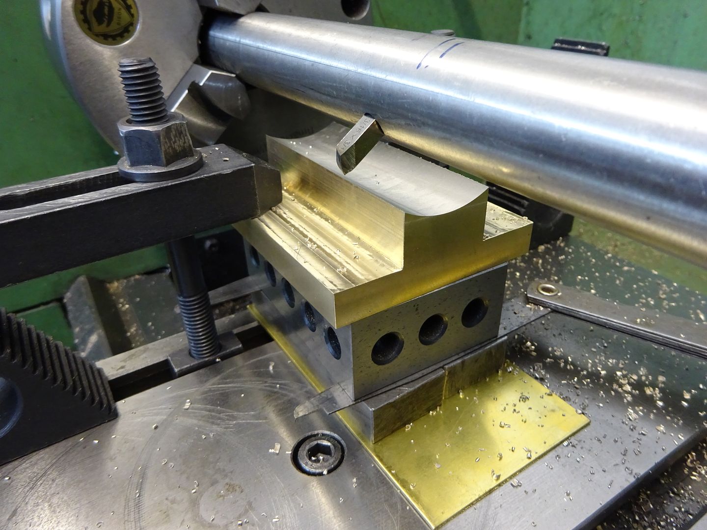
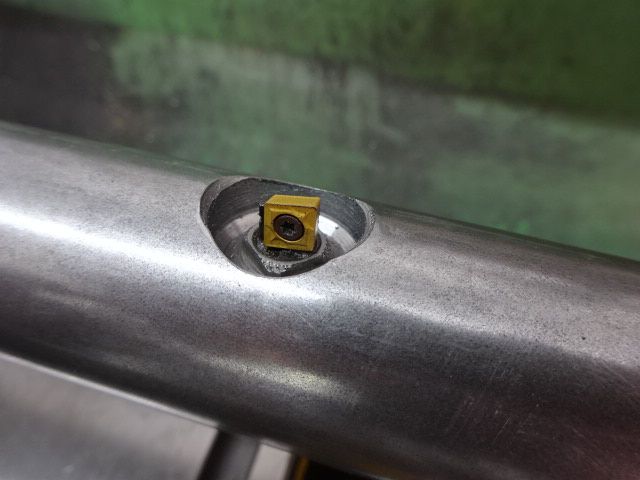
Ramon This pic should help explain it better. The turned portion is to ensure the diameter is true to the axis of the centres. Radius required is dimension plus .462 across tool tip and flat
Edited By Ramon Wilson on 11/11/2020 08:52:42 |
| JasonB | 11/11/2020 10:18:34 |
 25215 forum posts 3105 photos 1 articles | Yes just soft solder them together for machining. As Ramon says a between ctrs bar is easy to make, mine are not even solver steel.
|
| Dr_GMJN | 11/11/2020 16:35:17 |
1602 forum posts | Thanks guys. The setting up of the cylinder and feet is a challenge. I'll have to re-read the article. The plane of the feet faces has to be parallel to the nominal cylinder axis, and the valve face at the top, and they have to be aligned laterally with the cylinder axis. Also, so that when the cylinder is bored, and the valve face and feet are finally machined, they are the same thicknesses, and the cylinder walls are consistent. I suppose the boring would be done last, resting on the finished feet. Then the valve face would be machined in the same way, parallel to the feet? It's not so easy. I can imagine getting everything done nicely, then finding the cylinder is offset in the casting. I suppose the final boring could be done to the best-fit in the cylinder casting, but then the cross-slides would have to be adjusted to suit. That sounds all sorts of wrong.
|
| Dr_GMJN | 11/11/2020 16:37:51 |
1602 forum posts | Ramon, can you direct me to where the cutters are for the bar please? I'd prefer to use carbide inserts. Is it a round section tool holder that would fit into the cross-hole? |
| JasonB | 11/11/2020 17:25:24 |
25215 forum posts 3105 photos 1 articles | You will be hard pushe dto find an insert holder to swing that small a radius, A piece of 3/16" dia HSS would be about the right size, maybe upto 1/4" dia. Old ctr drill or milling cutter shank will do nicely. I do habe an insert tool but that goes into my little 35mm dia bar
There are three ways to go with the cylinder. 1. bore it out and face the piston end first then hold it on an arbor to machine the feet and port face. 2. Machine the feet, then portface on the mill before setting up on the cross slide to bore the cylinder. 3. Bore and face then set up in the mill using the face as the ref to do feet and portface. |
| peak4 | 11/11/2020 18:08:50 |
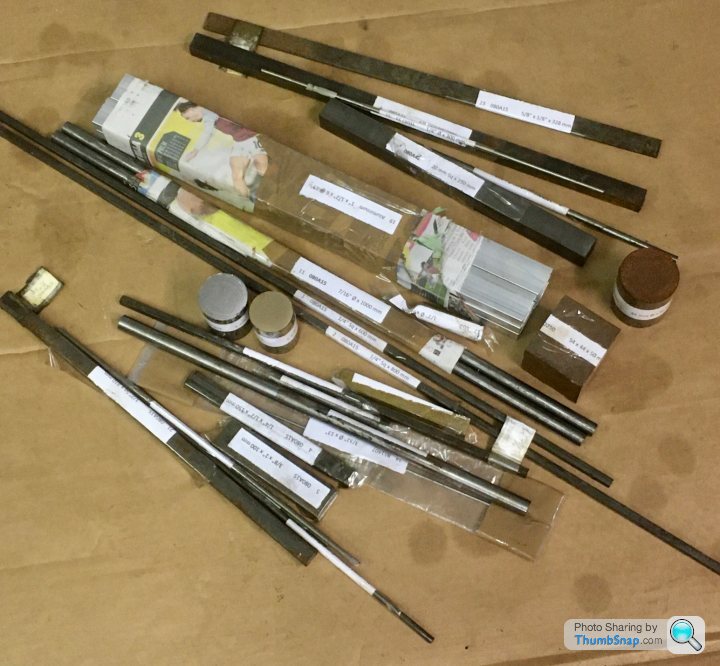
 2207 forum posts 210 photos | Posted by Dr_GMJN on 01/11/2020 22:22:39:
I've opted to buy only the castings. I will fabricate the beds from aluminium, and make the rest from stock materials, which I've already got from a local supplier: A good range of bits there; if you don't mind me asking, who was your local supplier? Bill |
| Ramon Wilson | 11/11/2020 18:55:03 |
1655 forum posts 617 photos | Well Doc, we all have differing ways to approach this subject and getting the feet true and parallel along with the valve face is critical as you surmise. Cat skinning is to the fore on this one. Personally I always do the bore first then use that as the datum to bring all other surfaces including the ends true to it - take a look here post 28 onwards or this one here post 24. The latter a much more complex casting for getting several surfaces and axis truly in relation. It's down to choice but I have always worked on the basis of what ever op is being done it should, if possible, lead to an accurate means for doing the next. Pays, money choice etc. I use HSS bits in my boring bars - somewhere though I have no idea where I have a few carbide tips set in a holder similar to Jasons but the tips are not replaceable. As said before I use discarded throw away cutter shanks for such purposes - excellent material and easily ground. I broke a 1.5 mm one this afternoon - the shank went straight in the cutter tin. You are seeking advice on here and you will recieve much - it is down to you to decide which suits your purpose best and choose accordingly. I offer mine based purely on my own previous personal experience which I hope will be of use - if not to yourself then perhasp some one looking in. Regards Ramon
PS Cut short by tea time !! I have more cutter shanks than I require - if you want some just say so and I'll send you some. Edited By Ramon Wilson on 11/11/2020 19:22:04 |
| Dr_GMJN | 11/11/2020 21:50:29 |
1602 forum posts | Thanks Ramon, I’ll fully digest all that later. What I’m trying to do is get some options together and go with the one(s) I feel most comfortable with. I stuck the 10V cylinder in a chuck and bored it out, simple! I know a between centres approach is probably better for these longer cylinders, so I’ll go with that despite it being totally new to me. I suppose fear of the unknown, and potentially scrapping a casting. Having said that, one of the 10V Cylinder faces was a bit out of true, so even that wasn’t so easy! Boring the cylinder first makes sense. I can put a mandrel in it and use that to get the axis, and offset from that vertically and horizontally for subsequent operations on the valve face and feet. I guess for the initial boring operation I could sit the casting on the cleaned-up valve face? Thanks for the kind offer of the tools. I do have some scrap milling cutters from my first attempts at milling earlier this year! Thanks anyway - I’ll see how I get on. |
| Dr_GMJN | 11/11/2020 22:04:23 |
1602 forum posts | Posted by peak4 on 11/11/2020 18:08:50:
Posted by Dr_GMJN on 01/11/2020 22:22:39:
I've opted to buy only the castings. I will fabricate the beds from aluminium, and make the rest from stock materials, which I've already got from a local supplier: A good range of bits there; if you don't mind me asking, who was your local supplier? Bill Yes, it’s Metals Procurement in Rotherham. Mark is the owners name. I think he is an ex steel works metallurgist. He knows his stuff and is very helpful. I did ask him if many customers are model engineers. He said that many years ago he put an advert in a M.E. Magazine and was inundated with requests for tiny amounts of material! I guess predictable, but I don’t think he bargained for the amount of calls. He said he still gets calls from the same advert - these people don’t throw magazines away! There are a few bits of round bar he couldn’t get, but the majority was no problem. The fact he’s only about 20 minutes away makes it very useful too! The whole lot shown there - stainless, silver, mild, aluminium, brass, gunmetal, cast iron) was about £70/£80.
|
| Ramon Wilson | 11/11/2020 23:05:53 |
1655 forum posts 617 photos | Posted by Dr_GMJN on 11/11/2020 21:50:29:
Thanks Ramon, I’ll fully digest all that later. What I’m trying to do is get some options together and go with the one(s) I feel most comfortable with. I stuck the 10V cylinder in a chuck and bored it out, simple! I know a between centres approach is probably better for these longer cylinders, so I’ll go with that despite it being totally new to me. I suppose fear of the unknown, and potentially scrapping a casting. Having said that, one of the 10V Cylinder faces was a bit out of true, so even that wasn’t so easy! Boring the cylinder first makes sense. I can put a mandrel in it and use that to get the axis, and offset from that vertically and horizontally for subsequent operations on the valve face and feet. I guess for the initial boring operation I could sit the casting on the cleaned-up valve face? Thanks for the kind offer of the tools. I do have some scrap milling cutters from my first attempts at milling earlier this year! Thanks anyway - I’ll see how I get on. You are at what I was faced with 45years ago - early days, so much to learn, so much to take in. The major difference of course was that the only way I could get help was via a monthly model club meeting - I well remember going from person to person asking if anyone could help me with trying to cut a thread on silver steel - each in turn referring me to someone else. Finally I gave up getting nowhere and struggled on with this most trying of machining but it would be quite a few years before I realised that the persons concerned probably didn't actually know anyway. I became so enarmoured with machining I gave up a lucrative offshore career and retrained as a milling machinist. From that point on I until I retired I worked in three 'jobbing' shops and one in a factory environment, building up and running a machine shop. In all that time I never, save one item, machined anything that I couldn't lift on the machine myself. Every day was different in the jobbing shops and as you can imagine it was a steep learning curve - time is money and mistakes highly unpopular. I say this because I have seen both sides of the fence - first as a rank amateur and second as having to earn a living. I have not forgotten how difficult it is to find your way in the early stages of ME hence my interest in helping those in similar circumstances but there are always many many ways of going about something - some good some not so - but the choice of how is very much down to the individual. So, with regards to the cylinder - if the bore goes in first then yes you do need a good datum face and yes the ideal one is usually the valve face. (that face should not be taken down to finished dimension at this stage - merely cleaned up flat) Once that bore is finalised then all other faces are brought to it ideally by holding on a close fitting mandrel (not like the cylinder in the first link where it can sit slightly off set). It's far easier to check these faces to the bore and have time to make allowances if not quite right than by finding your bore is out to them if machined first and the only way it can be rectified is by making it larger, possibly having to sleeve it. Expanding mandrels are very easy to make - they can be held in a chuck but if the back face is faced first and drilled and tapped it can then be bolted square to an angle plate if transfering to the mill is required and you don't have a means to support the chuck eg dividing head. The discarded cutters I have all have 6mm or 1/4 inch shanks - offer's still open if they suit your purpose Regards - Ramon Edited By Ramon Wilson on 11/11/2020 23:21:44 |
| peak4 | 11/11/2020 23:41:45 |
2207 forum posts 210 photos | Posted by Dr_GMJN on 11/11/2020 22:04:23:
Yes, it’s Metals Procurement in Rotherham. Mark is the owners name.................... Cheers for that, see also Phoenix Steels in Attercliffe for silver and tool steels, Canal St just off Effingham Rd. and also AMB for stainless and alloy; their yard prices are better than the web prices; again not far away, a non descript gate on Washford Road. Bill |
| Dr_GMJN | 13/11/2020 22:41:54 |
1602 forum posts | Thanks all. Thinking about the between centres boring bar: what’s the most accurate way of centering the ends, assuming it’s too large a diameter to fit through the spindle? Ive not done anything between centres before, but I do have a drive plate/carrier. Should I mill a flat on the end for the carrier? I realise at the moment there are a lot of questions and no progress on the model - I’m trying to get things worked out and tools ready before starting. The drawings for the bases are done and I have the material for them, they will be started first. Just waiting for the JB weld to arrive. |
| Steviegtr | 13/11/2020 22:55:56 |
 2668 forum posts 352 photos | When i bought some JB weld they had various ones on the shelf. This one was rated the strongest, but not sure as it is the 1st time i have used it. It was the figures they gave that prompted me to go for this one. Steve.
|
| Ramon Wilson | 13/11/2020 23:11:43 |
1655 forum posts 617 photos | If the bar won't go up the spindle its best to use a fixed steady if you have one. If not insert it in the chuck as deep as it will go and nip up but not over tight. Gently tap the outer end to tweak the concentricity - it's not that important as long as it's reasonable - and gently start the centre drill - once it has a start then drill as normal. Reverse and do the other end and yes ideally mill a small flat for the carrier. Set between centres and where you intend to have the cutter placed turn down the minimum to achieve a concentric surface about an inch wide. Transfer to the mill for the cutter hole and grubscrew hole - as said before make the cutter hole blind if you want the means to adjust the cutter in very small amounts. Getting started on the model isn't a factor at the moment. Keep on doing what you are - preparing the ground and asking questions so when you do you are ready for it
Stevie - that is the strongest (and the slowest cure) the other versions do not have the same strength or temperature characteristics.
Regards - Ramon Edited By Ramon Wilson on 13/11/2020 23:15:06 |
| Dr_GMJN | 14/11/2020 12:51:05 |
1602 forum posts | OK. So in terms of aligning the cylinder on the cross-slide, ready for boring, I'm thinking of turning a hardwood plug, and centering each end of that, then tapping it into the cast bore. I can then use the vernier points to make sure the outside of the casting ends are more or less concentric with the bore (as with teh 10V). It will make machining the cast O/D's more consistent for fitting whatever cladding I decide on. I can then use the head and tailstock centres to make sure it's aligned before clamping everything down. I suppose it would be good to tighten the cross slide gibs as well? On the cladding - I'm not sure whether to stick with aluminium, or try wooden strips. I like aluminium better, but it seems like a tricky job to cut it to the cylinders, what with the feet and valve blocks etc. |
| Ramon Wilson | 14/11/2020 13:04:51 |
1655 forum posts 617 photos | Posted by Dr_GMJN on 14/11/2020 12:51:05:
OK. So in terms of aligning the cylinder on the cross-slide, ready for boring, I'm thinking of turning a hardwood plug, and centering each end of that, then tapping it into the cast bore. I can then use the vernier points to make sure the outside of the casting ends are more or less concentric with the bore (as with teh 10V). It will make machining the cast O/D's more consistent for fitting whatever cladding I decide on. I can then use the head and tailstock centres to make sure it's aligned before clamping everything down. I suppose it would be good to tighten the cross slide gibs as well?
How do you intend to hold it ? Do you have an angle plate or vertical slide? Yes lock the gib screws |
| Dr_GMJN | 14/11/2020 13:23:11 |
1602 forum posts | I was just going to remove the top slide assembly, and block it up directly from the cross-slide t-slot table. It would sit either on it's feet, or on the valve face (I'd have flatted it with a file and on the surface plate, ready for final machining later). Then clamp it with a bar (or two) over the top. If I've understood correctly, I progressively move the cutter out from the bar until I get to the right diameter - The cylinder itself only moves left to right by means of the saddle? |
| JasonB | 14/11/2020 13:23:50 |
25215 forum posts 3105 photos 1 articles | That sounds to be the way Westbury did it on packing clamped to the cross slide a method I have used on several cylinder. Do think ahead as to how you will machine at least the piston end of the cylinder's end flange square to the bore and also how you will do the final finishing of the feet and port face. Don't know if I dare suggest flycutting the end of the cylinder while it's still undisturbed and attached to the topslide If I did the fabricated version I would hold in 3 or 4-jaw (not sure which will fit) to bore and face one end and then machine everything relative to those surfaces. Edited By JasonB on 14/11/2020 13:42:28 |
| Dr_GMJN | 14/11/2020 16:31:36 |
1602 forum posts | Posted by JasonB on 14/11/2020 13:23:50:
That sounds to be the way Westbury did it on packing clamped to the cross slide a method I have used on several cylinder. Do think ahead as to how you will machine at least the piston end of the cylinder's end flange square to the bore and also how you will do the final finishing of the feet and port face. Don't know if I dare suggest flycutting the end of the cylinder while it's still undisturbed and attached to the topslide If I did the fabricated version I would hold in 3 or 4-jaw (not sure which will fit) to bore and face one end and then machine everything relative to those surfaces. Edited By JasonB on 14/11/2020 13:42:28
I'm happy to do the bore and facing in the 4 jaw chuck, as with the 10V. I thought the whole point of the boring bar between centres was that it's more accurate for longer cylinders? Then again is it really that different than the 10V - it appears to work fine? Seems far easier to do in the chuck assuming it can be held in there. I'll still use fly cutting for as much as I can - I really dislike the look of a milled surface, at least the ones I do! I didn't know there was a fabricated version. Do you mean as in milled from solid bar? |


Please login to post a reply.
Magazine Locator
Want the latest issue of Model Engineer or Model Engineers' Workshop? Use our magazine locator links to find your nearest stockist!
Sign up to our Newsletter
Sign up to our newsletter and get a free digital issue.
You can unsubscribe at anytime. View our privacy policy at www.mortons.co.uk/privacy
Latest Forum Posts
- *Oct 2023: FORUM MIGRATION TIMELINE*
05/10/2023 07:57:11 - Making ER11 collet chuck
05/10/2023 07:56:24 - What did you do today? 2023
05/10/2023 07:25:01 - Orrery
05/10/2023 06:00:41 - Wera hand-tools
05/10/2023 05:47:07 - New member
05/10/2023 04:40:11 - Problems with external pot on at1 vfd
05/10/2023 00:06:32 - Drain plug
04/10/2023 23:36:17 - digi phase converter for 10 machines.....
04/10/2023 23:13:48 - Winter Storage Of Locomotives
04/10/2023 21:02:11 - More Latest Posts...
- View All Topics
Support Our Partners


Shopping Partners
Subscription Offer

Latest "For Sale" Ads
- Reeves** - Rebuilt Royal Scot by Martin Evans
by John Broughton
£300.00 - BRITANNIA 5" GAUGE James Perrier
by Jon Seabright 1
£2,500.00 - Drill Grinder - for restoration
by Nigel Graham 2
£0.00 - WARCO WM18 MILLING MACHINE
by Alex Chudley
£1,200.00 - MYFORD SUPER 7 LATHE
by Alex Chudley
£2,000.00 - More "For Sale" Ads...
Latest "Wanted" Ads
- D1-3 backplate
by Michael Horley
Price Not Specified - fixed steady for a Colchester bantam mark1 800
by George Jervis
Price Not Specified - lbsc pansy
by JACK SIDEBOTHAM
Price Not Specified - Pratt Burnerd multifit chuck key.
by Tim Riome
Price Not Specified - BANDSAW BLADE WELDER
by HUGH
Price Not Specified - More "Wanted" Ads...
Get In Touch!
Do you want to contact the Model Engineer and Model Engineers' Workshop team?
You can contact us by phone, mail or email about the magazines including becoming a contributor, submitting reader's letters or making queries about articles. You can also get in touch about this website, advertising or other general issues.
Click THIS LINK for full contact details.
For subscription issues please see THIS LINK.
Digital Back Issues


Donate

 Register
 Log-in
Model Engineer Magazine
- Percival Marshall
- M.E. History
- LittleLEC
- M.E. Clock

ME Workshop
- An Adcock
- & Shipley
- Horizontal
- Mill

Subscribe Now
- Great savings
- Delivered to your door

Pre-order your copy!
- Delivered to your doorstep!
- Free UK delivery!
All Forum Topics > Work In Progress and completed items > Stuart Twin Victoria (Princess Royal) Mill Engine