Forum sponsored by:

Old School Drawing Exercises and 2D CAD
| Georgineer | 02/07/2020 00:34:42 |
| 652 forum posts 33 photos | When I did a course to learn Autocad a few years ago (having learned my draughting the old fashioned way) I was actually marked down for blending my curves too accurately! Our drawings were marked by overlaying them with a master drawing supplied to our lecturer by City and Guilds, and I lost marks because mine wasn't an exact match. I pointed out that my blending was smoother than theirs, so he took it up with C & G. Their response was that I shouldn't be able to do that at level 2 and that their marking scheme stood. Fortunately our lecturer was a very determined man, and took it as far up their hierarchy as he needed to. Eventually they conceded that doing it better than the minimum required wasn't actually a fault, and I was awarded full marks. George B. |
| Nigel Graham 2 | 02/07/2020 01:58:49 |
| 3293 forum posts 112 photos | My wretched typing! I'd about finished this when yet again I hit an unknown key-combination and deleted it. Orthographic! Yes of course! Thank you gentlemen for the correction! Same root though. Of course I am aware that CAD calls the 3D images "models", but TurboCAD's view-changing tool offers two types of view and calls one isometric. I forget the other. I am also well aware of the industrial practice now being taken up in some ways by model-engineers, of drawing-files translated straight to CNC-machine drivers. ' Really, for us amateur engineers the choice of whether to use CAD, and to what extent, is by budget, time, preference, learning-ability and indeed interest. First we are assuming designing our own projects, rather than sticking to published ones; and considering their complexity. This was my starting-point, as my main project's source is merely a few scrappy old trade photographs from 1908; and I bought a copy of TurboCAD 19 Pro. Next, unless you have a particular gift for learning extremely difficult and unintuitive software, which I do not, it can take a formidable time to grasp sufficient CAD experience just for simple orthographic drawings adequate for your own purposes. 3D-model drawing adds greatly to the complexity; and when designing for yourself, you need ask why lumber yourself when you actually make the parts from 2D drawings. The one advantage I see, was that CAD enables 3D models to help determine complete assemblies. This too, helped sway my decision. However, as engineers we should be able to visualise a 3D assembly from 3 orthographic views - depending on its nature. So why 3D CAD for own drawings for own projects in own workshops...? The only answers I can see are that either you have the desire, time and ability to learn it, or you've bought a CAD package that gives you no choice! If we buy CAD because we want to design our projects, presumably we can already create engineering-drawings of appropriate standard. The trap is that of trying to learn the CAD package taking much longer than we would have spent drawing the project manually. I bought TurboCAD but really, that it lets me draw a 3D image of, say, my engine's crankshaft does not mean I have to do so. I want to make a real crankshaft, not a pretty picture of one, and after untold hours of struggle better spent actually designing and making the engine, I was just about capable of a pretty picture of the shaft. By then I had made it, to a CAD drawing but orthographic, dimensioned and set out from the orthographic GA. I did try other CAD packages. I have a copy of AutoCAD 2000, which is 2D only I think, but no manual for it. I found Fusion 360's brashness off-putting, and it assumes prior CAD-principles knowledge - to be fair, they all do. I tried Alibre but I missed two episodes of the MEW serial. Why buy and learn a complete new package when I'd already bought TurboCAD? I thought the magazine series would make it easier to learn, than trying to teach myself what I already had. So I abandoned Alibre too - which took its publishers months to understand. Luckily, I already have a scribing-block. Both Fusion and Alibre are based on 3D- model first - I do not use a 3D CAD/CAM system at home, so regard 3D as nice-to-have, but of limited use, extremely difficult and time-consuming to learn and frankly, not really necessary. It is for brochure artwork, not workshop drawings. The only useful 3D images I have drawn were two geological diagrams for a caving-club magazine article. ' Training materials? TurboCAD's own on-line 'Help' manual is not much 'Help'; and I can't learn from videos. Far better than these is Paul Tracy's CD manual for TurboCAD, a step-by-step pdf primer. D.A.G. Brown's general CAD primer has a very dated cover photograph, but does outline the principles of CAD engineering-drawing. Neill Hughes' more modern alternative, which I also own, is sketchier and more for the 3D-artwork people - and despite a British author and publisher, neighbours to France, it insists on calling "metres", "meters". ' So to sum up, CAD can help us but it is not the be-all-&-end-all of model-engineering. Unless you also intend using CNC machine-tools as well, or buying a lot of profiled work-pieces, CAD is only worth buying if - you design most of your own projects, you need draw them accurately, manually drawing them would take much longer than learning the CAD package sufficiently. |
| pgk pgk | 02/07/2020 05:50:14 |
| 2661 forum posts 294 photos | It used to be possible to pick up a previous edition of turbocad for around a tenner from Maplins (and way back when one could download version 3 for free). At that price point they were well worth having. I'm no draughtsman or particularly good with the program because i don't use it much but it's great for things like trying to figure the best way to lay out a part or even where to place the machine footprints in your new shed - less messy than cutting out cardboard shapes and sliding them around on a paper plan. pgk |
| JasonB | 02/07/2020 07:20:19 |
 25215 forum posts 3105 photos 1 articles | Posted by Nigel Graham 2 on 02/07/2020 01:58:49:
So why 3D CAD for own drawings for own projects in own workshops...? The only answers I can see are that either you have the desire, time and ability to learn it, or you've bought a CAD package that gives you no choice! For me the ability to assemble and move all the part on the screen to check for fits and clearances is a big bonus before I cut metal, can't do that with 2D. Once modelled then 2D drawings can be produced to take to workshop. Anyone with CNC will also want to take advantage of its 3 (or more) axis of movement so having the part drawn in 3D is needed. Same applies to those with 3D printers either for printing finished items or maybe printing test items before cutting from metal. No paper drawings would be used in this case as straight from screen to memory stick and into machine. It can also be handy if you want to know weight or volume of an item which is just a click away even for complex shapes |
| JasonB | 02/07/2020 07:21:34 |
25215 forum posts 3105 photos 1 articles | I've given up on Dave's latest challenge, spent all night trying to draw the basic triangle with just a compass and failed, let alone getting a circle to fit inside |
| Andrew Johnston | 02/07/2020 07:47:23 |
 7061 forum posts 719 photos | Posted by SillyOldDuffer on 01/07/2020 17:40:18:
Another Geometrical Drawing. What's the radius of the largest circle that can be drawn inside this isosceles triangle? Should be able to solve it analytically, although that will involve maths. Andrew |
| pgk pgk | 02/07/2020 08:35:45 |
| 2661 forum posts 294 photos | Posted by JasonB on 02/07/2020 07:21:34:
I've given up on Dave's latest challenge, spent all night trying to draw the basic triangle with just a compass and failed, let alone getting a circle to fit inside Very difficult to draw the outline of a triangle without a ruler but I'd guess that drawing enough circles round a circle of same radius and building them up gives a grid from which you could pick the proportionate points or even create a virtual graph paper?? I'm just too lazy to try. As an intuitive assessment I'd reckon that a circle within a square whose top is near as dammit 12 squares up from the bottom should do it and use the compass to measure that diagonal over the circle points created? There's probably some more sane way of doing it. pgk |
| Former Member | 02/07/2020 09:21:14 |
[This posting has been removed] | |
| IanT | 02/07/2020 09:52:31 |
| 2147 forum posts 222 photos | Posted by Nigel Graham 2 on 02/07/2020 01:58:49:
So why 3D CAD for own drawings for own projects in own workshops...? The only answers I can see are that either you have the desire, time and ability to learn it, or you've bought a CAD package that gives you no choice! An interesting question Nigel and the answer will be dependent on quite a few factors. I have used TurboCAD DL for many years and regard myself as proficient (rather than expert). For some simple 2D outlines, I might still use it, although it is not parametric. I tried 3D in TC/DL and failed dismally. My approach to a drawing was to get everything into model space somewhere (often several iterations for different 'edits' ) and sort things out via 'views'. So you are drawing at a global level in one sense. I spent a lot of time using construction lines to ensure different projections were matched dimensionally. I also made extensive use of layers in term of separating 'bits' from each other... 2D might have been sufficient for my needs until I purchased a 3D printer, at which point I wanted much more specific designs than Thingiverse was ever going to provide. A friend recommended Open SCAD and it was a very good solution for my relatively simple 3D print needs. I have used existing SCAD models, modified them and also created my own. It is a simple and elegant tool that can be learned in small steps and used almost instantly. Given its 'designs' are text based, it is also a very good (easy) way to share 'things' with others. I would use it to teach children about 3D concepts rather than a more complex 3D CAD system. However, SCAD will never be my 'engineering' design tool of choice (simply one of my 3DP 'tools' ) For something to replace TC/DL I wanted a 3D package that was modern, powerful and that I could actually manage to learn. Cost was a factor and content ownership (e.g. Cloud based?) another. Plenty of debate here about which 3D package is the best but for me Solid Edge seems to fit my requirements. I've been learning and using it for a few weeks now and I'm very happy with all I've discovered. One of the things that is very different of course, is the change in design thought processes. The SE system forces my to think of everything as 'parts' and 'assemblies' (and the hierarchy of sub-assemblies etc). I can define the parts material and many other aspects of the design - which immediately tends to promote other decisions - shall I print this part or machine it? Could that small spacer piece be hardwood, metal or 3D printed? How would I fabricate this part (or should I even try - if it requires more/smaller parts). I've found the journey most interesting and enjoyable. Whether I am a better or more productive modeller, I'm not sure at the moment but it's been fun and that's why I do this stuff - for my personal satisfaction and entertainment. Take Care Everyone IanT Edited By IanT on 02/07/2020 09:53:12 |
| Gary Wooding | 02/07/2020 10:34:32 |
| 1074 forum posts 290 photos | No CAD, no compass, no ruler, just pencil and trig. Do I get double points?
|
| Former Member | 02/07/2020 10:47:43 |
[This posting has been removed] | |
| Martin Connelly | 02/07/2020 10:58:43 |
 2549 forum posts 235 photos | We had a drawing of a pipe at work, done by a professional draughtsman with years of experience, that I had to point out was impossible to make. He said if we can draw it you can make it. What he had drawn was the equivalent of a Penrose triangle. If he had 3D CAD it would have been obvious but he was doing it 2D. I learnt to use AutoCad when it was 2D from the supplied paper manual that had a very good tutorial to work through. I was also lucky enough to be doing it at work so effectively was paid to learn it. Going to 3D was not hard as I spent a lot of time at work checking drawings for production before they were issued. You learn to turn 2D images into your own internal 3D model as a result. The triangle problem is simple, learnt that in maths at school. Bisect one of the base angles and project the line to the centre line. Estimate by eye gives 7, trig gives 7.2 if I remember yesterday's result correctly. Martin C |
| Neil Wyatt | 02/07/2020 11:06:02 |
 19226 forum posts 749 photos 86 articles | Bisect two angles of the triangle, three arcs per vertex. Centre the triangle where the bisecting lines cross. Draw a circle tangential to the sides of the triangle. Blimey must be remembering that from school. Neil Edit: (Works with all triangles and strictly you only need to bisect two angles, thinking about it!) Edited By Neil Wyatt on 02/07/2020 11:08:07 |
| blowlamp | 02/07/2020 11:10:17 |
 1885 forum posts 111 photos | Easy in CAD whichever way you do it.
|
| pgk pgk | 02/07/2020 11:25:34 |
| 2661 forum posts 294 photos | Posted by Neil Wyatt on 02/07/2020 11:06:02:
Bisect two angles of the triangle, three arcs per vertex. Centre the triangle where the bisecting lines cross. Draw a circle tangential to the sides of the triangle. Blimey must be remembering that from school. Neil Edit: (Works with all triangles and strictly you only need to bisect two angles, thinking about it!) Edited By Neil Wyatt on 02/07/2020 11:08:07 ..so you cheated and used a straight edge..folding might have been permitted...
pgk |
| SillyOldDuffer | 02/07/2020 11:30:30 |
| 10668 forum posts 2415 photos | Posted by pgk pgk on 01/07/2020 22:26:21:
70mph round a 100 metre curve? I'd guess you're tilting it 90 degrees and fitting ejector seats... pgk Absolutely! Engineering is about balancing cost and practicality, and it isn't easy. Given the clue that the operators wish to maintain an average 70mph over the length of the line, the engineer must pay careful attention to the design of this reverse curve. He can't assume it's OK for trains to take the curve at 5mph; the curve has to be optimised for speed. As building railway line is too expensive to let practical men experiment on the job, this was done with drawing boards, slide rules and maths in an office. So what is the maximum speed a train can be safely taken round a well-designed 100 metre curve? Transition curves and super-elevation (banking) allowed. In the history of railway building, it was common for lines to be routed cheaply at first because money was short. They put up with slow tight curves, gradients, weak bridges, and long diversions even though these hack profits down year on year. When money was available later inefficiencies were often eliminated by building cut-offs. A good way of getting rid of a reverse curve is to connect both sides with a direct tunnel or viaduct, but these have to pay for themselves by increasing the railways efficiency. No place for practical men in this type of engineering either - it's all about cost estimating. Practical men have the skills needed dig tunnels, but the hard part is making the railway pay. Dave
|
| Neil Wyatt | 02/07/2020 11:44:56 |
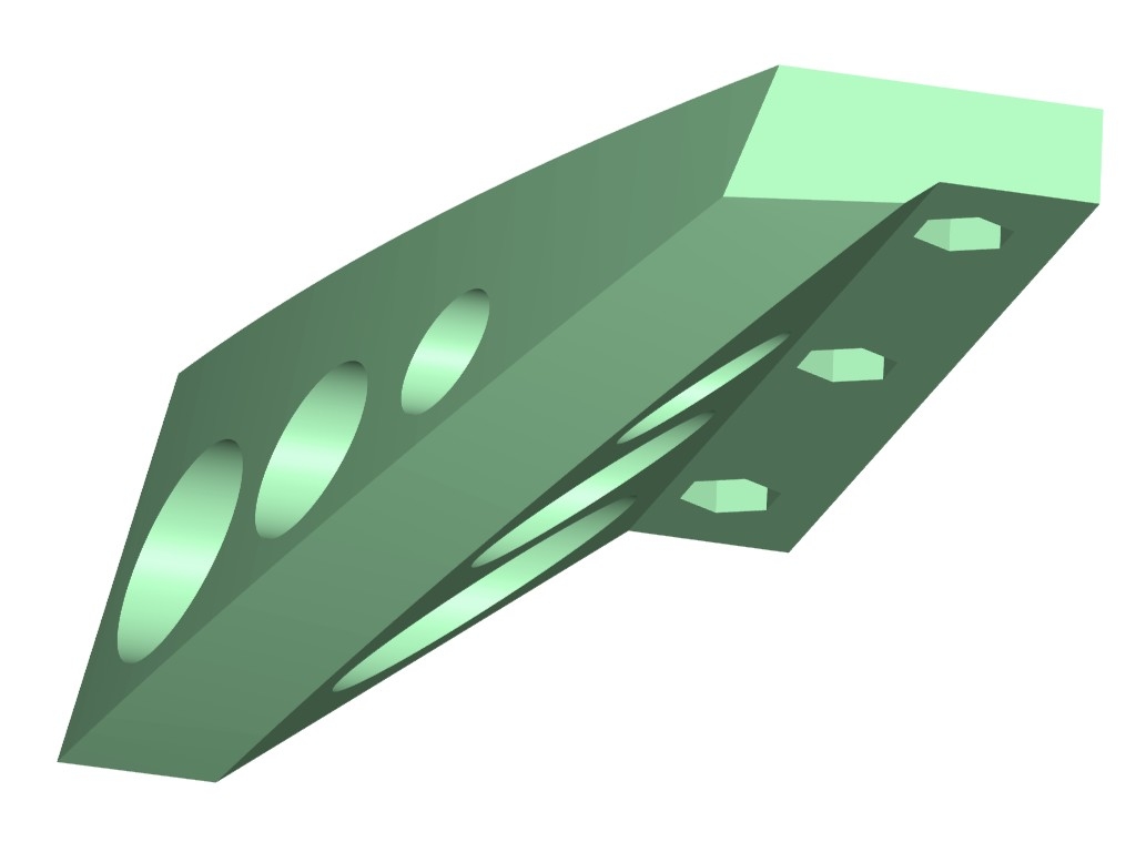
19226 forum posts 749 photos 86 articles | I think the values of 3D CAD is very much in it's flexibility to meet the different needs of different people. It goes without saying that those of us who use CAM or 3D printing would be lost without 3D CAD. The sector for my equatorial platform (below) has curves in two intersecting planes, as a result of the bottom surface being an inclined slice of a cone. Not only is it elliptical, but curved and tapered too. Tricky to draw in 2D but with significant advantages over the traditional circular (the load is borne vertically, not at 38 degrees to the horizontal) and elliptical (the load bearing point moves back an forth) designs. It also needs to be reasonably accurate to work well, although any errors are mitigated by the large radii ( about 383mm and 500mm). Making it in wood or metal would require CNC or a very large jig. 3D printing, it's almost as easy as making any other shape (just some thought about support placement and orientation needed).
For me, then, 3D Cad opens doors that would otherwise be closed. Another example is this control box. Aside from 3D printing it it would not be hard to draw it on paper in 2D, but I would have had to construct an isometric view to get a real feel for how it would look. When aesthetics as well as function are important, 3D CAD win hands down. Incidentally, most of the making of this box was effectively working in 2D, but being able to create angled planes and project of existing surfaces greatly eases tasks like creating the close fitting tabs on the angled base.
I do use a very basic 2D CAD (a ~20-year-old version of Corel Draw) for some tasks, like setting out telescope optics. When I made a telescope with a Crayford focuser, although 2D (actually in TurboCAD) was useful for calculating the overall dimensions, I switched to 3D to get the proportions right before cutting metal. It this case my 3D 'model' wasn't very developed at all, but without it most of the work would have been 'cut and try'. I think people often forget that 3D CAD and do anything 2D can do, with the advantage of instantly viewing results in 3D, if desired. Many of the uses and advantages of 3D CAD I've found are not obvious and you tend to discover them through your projects, rather than being led by the capabilities of the CAD. The other thing is how you learn by doing. My designs are much more efficient now - for example I've learned to create one feature then mirror or pattern it rather than drawing them all individually. This means if there's a change you just edit the original, a huge timesaver. Neil |
| Neil Wyatt | 02/07/2020 11:54:53 |
19226 forum posts 749 photos 86 articles | Posted by SillyOldDuffer on 02/07/2020 11:30:30:
In the history of railway building, it was common for lines to be routed cheaply at first because money was short. They put up with slow tight curves, gradients, weak bridges, and long diversions even though these hack profits down year on year. When money was available later inefficiencies were often eliminated by building cut-offs. A good way of getting rid of a reverse curve is to connect both sides with a direct tunnel or viaduct, but these have to pay for themselves by increasing the railways efficiency. No place for practical men in this type of engineering either - it's all about cost estimating. Practical men have the skills needed dig tunnels, but the hard part is making the railway pay. Dave
Move onto to motorway and major road design and construction up to the 1970s and 80s... woodland had a lower cost per acre than farmland so planning could be a sort of ecological 'join the dots'. Look at this example on the M50 where the planners managed to neatly align a couple of miles of the motorway just inside the woodland...
|
| pgk pgk | 02/07/2020 11:56:26 |
| 2661 forum posts 294 photos | Posted by SillyOldDuffer on 02/07/2020 11:30:30:
So what is the maximum speed a train can be safely taken round a well-designed 100 metre curve? Transition curves and super-elevation (banking) allowed. Dave
I'll start by stating that I ain't gotta clue about the limitations applying to a real world case but in my world with unlimited lead-in (transition) and no issues regarding wheelbase or suspension or carriage length or engine type then the only limit should be design to cope with the aerodynamics of breaking the sound barrier and the G-force limitations on the driver. Make it autonomous as a train and your limitation becomes dependant on available power - you'll never get anywhere near C but a good chance that wat comes out of the bend is a thin superheavy new alloy.
pgk |
| Gary Wooding | 02/07/2020 12:22:41 |
| 1074 forum posts 290 photos | I made this knurling tool some years ago and kept it in a cupboard together with 4 pairs of different knurls in a plastic bag. I often toyed with the idea of making a fitted box for it, but was put off by the awkward shapes. Eventually I bit the bullet, designed the 3D model in Fusion and am about to 3D print it. 2D CAD would have been very difficult.
|


Please login to post a reply.
Magazine Locator
Want the latest issue of Model Engineer or Model Engineers' Workshop? Use our magazine locator links to find your nearest stockist!
Sign up to our Newsletter
Sign up to our newsletter and get a free digital issue.
You can unsubscribe at anytime. View our privacy policy at www.mortons.co.uk/privacy
Latest Forum Posts
- *Oct 2023: FORUM MIGRATION TIMELINE*
05/10/2023 07:57:11 - Making ER11 collet chuck
05/10/2023 07:56:24 - What did you do today? 2023
05/10/2023 07:25:01 - Orrery
05/10/2023 06:00:41 - Wera hand-tools
05/10/2023 05:47:07 - New member
05/10/2023 04:40:11 - Problems with external pot on at1 vfd
05/10/2023 00:06:32 - Drain plug
04/10/2023 23:36:17 - digi phase converter for 10 machines.....
04/10/2023 23:13:48 - Winter Storage Of Locomotives
04/10/2023 21:02:11 - More Latest Posts...
- View All Topics
Support Our Partners


Shopping Partners
Subscription Offer

Latest "For Sale" Ads
- Reeves** - Rebuilt Royal Scot by Martin Evans
by John Broughton
£300.00 - BRITANNIA 5" GAUGE James Perrier
by Jon Seabright 1
£2,500.00 - Drill Grinder - for restoration
by Nigel Graham 2
£0.00 - WARCO WM18 MILLING MACHINE
by Alex Chudley
£1,200.00 - MYFORD SUPER 7 LATHE
by Alex Chudley
£2,000.00 - More "For Sale" Ads...
Latest "Wanted" Ads
- D1-3 backplate
by Michael Horley
Price Not Specified - fixed steady for a Colchester bantam mark1 800
by George Jervis
Price Not Specified - lbsc pansy
by JACK SIDEBOTHAM
Price Not Specified - Pratt Burnerd multifit chuck key.
by Tim Riome
Price Not Specified - BANDSAW BLADE WELDER
by HUGH
Price Not Specified - More "Wanted" Ads...
Get In Touch!
Do you want to contact the Model Engineer and Model Engineers' Workshop team?
You can contact us by phone, mail or email about the magazines including becoming a contributor, submitting reader's letters or making queries about articles. You can also get in touch about this website, advertising or other general issues.
Click THIS LINK for full contact details.
For subscription issues please see THIS LINK.
Digital Back Issues


Donate

 Register
 Log-in
Model Engineer Magazine
- Percival Marshall
- M.E. History
- LittleLEC
- M.E. Clock

ME Workshop
- An Adcock
- & Shipley
- Horizontal
- Mill

Subscribe Now
- Great savings
- Delivered to your door

Pre-order your copy!
- Delivered to your doorstep!
- Free UK delivery!
All Forum Topics > CAD - Technical drawing & design > Old School Drawing Exercises and 2D CAD