Forum sponsored by:

Colchester Student Mk1 Won't Start
| John Haine | 27/11/2019 09:32:13 |
| 5563 forum posts 322 photos | It's quite likely that the motor is fine, 3 phase induction motors are pretty robust. Frankly, I would remove and junk all the control gear, do / get done a proper safety test on the motor, and invest in a modern VFD rather than mess around with that horrible static converter. It will quite a beefy VFD but you get the benefit of variable speed, soft start, jogging etc. |
| SillyOldDuffer | 27/11/2019 11:37:46 |
| 10668 forum posts 2415 photos | Posted by Robert Atkinson 2 on 27/11/2019 07:33:00:
Posted by Richard Kirkman 1 on 26/11/2019 20:03:27:
Posted by Phil Whitley on 26/11/2019 18:23:24:
...
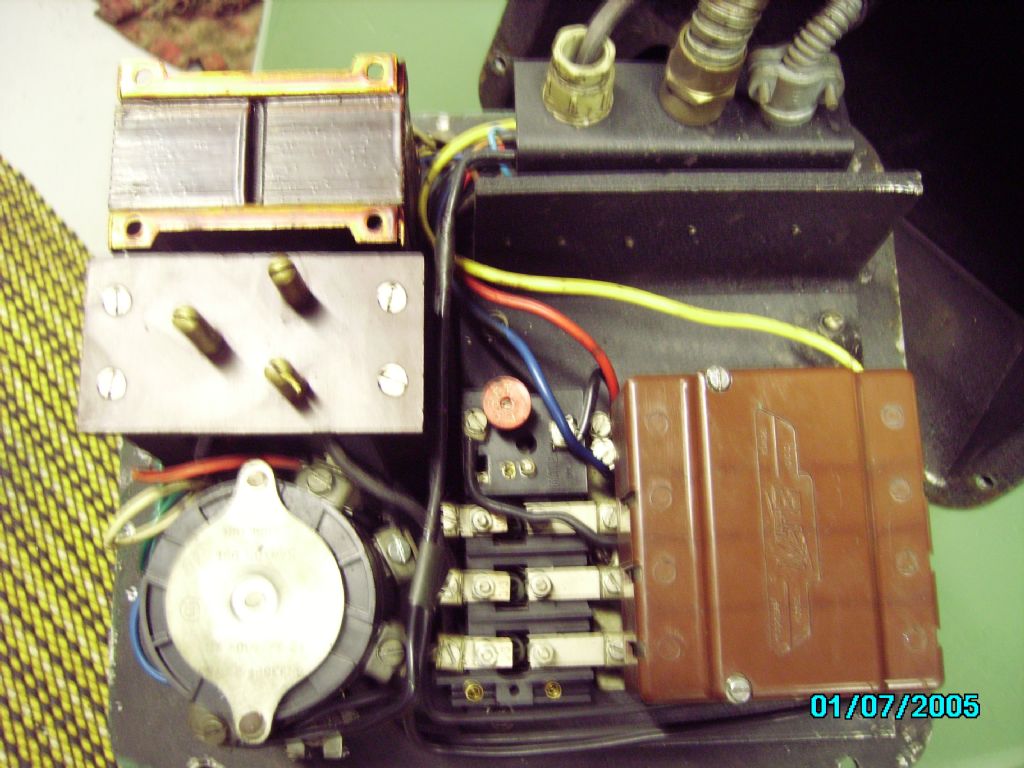
I'm getting quite confused with all these terms. Specifically which part is the contactor, is it this part? And if its not this part, what is this part and what does it do and why? Hi Richard, The item pictured with 3 contacts separated by grey (asbestos?) insulation panels is the contactor. The contacts don't look great. If you can hear this clunking with the start lever operation the PC40 is powering it. Do you have a multimeter / test meter? You really need to get into some fault finding. First thing would be to check the contactor contact resistance you can do this with it unpowered by manually closing it , pushing down on the brown (Tufnol) insulator that carries the moving contacts and then checking the resistance across each contact. Robert G8RPI. According to the circuit diagram the contactor has two pairs of 3 switches. One pair connects three phase to the pump and the other connects 3-phase to the main motor. Contactors are electrically operated switches. Basically a low safe voltage is applied to a magnet coil that pulls the switch contacts together, and they do all the heavy lifting. Your contactor is very old-fashioned; everything is out in the open, making it vulnerable to damp and dirt.
Joining the dots:
Although the contactor may be of obsolete design, the control circuit is isn't! Much the same is used on modern lathe.
Modern contactors like the example above come in nice sealed boxes, rather smaller than yours, with no maintenance required. Entirely possible to replace the old contactor with a new one, the main problem being to identify one with a 240V operating coil, and six switches. They're readily available. (Ignore the annotations - they're for a single-phase motor.) Dave |
| Richard Kirkman 1 | 27/11/2019 12:03:24 |
| 334 forum posts 799 photos | Posted by SillyOldDuffer on 27/11/2019 11:37:46:
Contactors are electrically operated switches. Basically a low safe voltage is applied to a magnet coil that pulls the switch contacts together, and they do all the heavy lifting. Your contactor is very old-fashioned; everything is out in the open, making it vulnerable to damp and dirt.
Joining the dots:
Although the contactor may be of obsolete design, the control circuit is isn't! Much the same is used on modern lathe.
Modern contactors like the example above come in nice sealed boxes, rather smaller than yours, with no maintenance required. Entirely possible to replace the old contactor with a new one, the main problem being to identify one with a 240V operating coil, and six switches. They're readily available. (Ignore the annotations - they're for a single-phase motor.) Dave Dave, I don't think the pump does actually run. I just hear it buzzing, but I don't think it's a loud enough buzz for the motor to be running. But the point is it's getting some electricity
When I turn the on switch, I hear a large clunk noise. But I think that's just the noise that the switch makes. I don't think the contactor has moved apart from when I'm in there. The tongue you mentioned is definitely missing, I hadn't noticed before. And I've only just noticed now, that another tab and contact that should be paired(the one that's broken in the bottom of the case) should probably go here?
The white/dirty white cable going from the bottom is the coolant pumps cable. So the blue wire has been put down there when it should be going onto the contactor above and have the tab which is loose in the bottom connecting the pump. Does that make sense to you? I'm just guessing sti, but it seems to be logical to me |
| David Davies 8 | 27/11/2019 12:53:51 |
 202 forum posts 1 photos | SOD, I think you are mistaken. ''According to the circuit diagram the contactor has two pairs of 3 switches. One pair connects three phase to the pump and the other connects 3-phase to the main motor.'' The Colchester diagram shows the coolant pump being started directly from the rotary switch, by 3 of the poles, the other three poles are connected to the line contactor and thermal overload and thence to the spindle motor. Hope this helps.
Dave
|
| larry phelan 1 | 27/11/2019 14:13:15 |
| 1346 forum posts 15 photos | Not sure if this will help or not but when I moved to the sticks I borrowed a static converter to try it out. It would run my lathe and mill, each 1.5 hp but not my planer or spindle moulder, each 4hp, just make buzzing noises. Problem was solved by buying a Transwave 10 hp rotary converter. This is big enough to run anything in the shop. Perhaps your converter is simply too small? Static converters do not seem to have the same kick as rotarys and sometimes you need to adjust loads ect, this can be A-Pain-in-the arse.. With the rotary, just switch on and walk away. |
| Swarf Maker | 27/11/2019 14:27:49 |
| 132 forum posts 7 photos | There seems to be some mis-reading of the circuit diagram going on here. The top set of switch contacts (6 off) in the upper part of the diagram all relate to the Santon switch. Rotating the switch from 'OFF' to 'ON' just turns on the coolant pump and the contactor has no part in this. Rotating the switch further additionally applies power to the terminals of the 'Motor Starter' (contactor). A contactor is used here to avoid the switch load on the Santon switch and to provide 'no-volt' release in the event of a power failure. It may also incorporate a means of disconnecting power to the motor if too much current is being taken. I will leave things at that point rather than confuse the points made above. |
| SillyOldDuffer | 27/11/2019 16:05:15 |
| 10668 forum posts 2415 photos | Posted by David Davies 8 on 27/11/2019 12:53:51:
SOD, I think you are mistaken. ''According to the circuit diagram the contactor has two pairs of 3 switches. One pair connects three phase to the pump and the other connects 3-phase to the main motor.'' The Colchester diagram shows the coolant pump being started directly from the rotary switch, by 3 of the poles, the other three poles are connected to the line contactor and thermal overload and thence to the spindle motor. Hope this helps.
Dave
Dave and Swarf Maker are correct - I've misread the diagram. A1 to to C2 refer to the Santon Rotary Switch, not the contactor! Please ignore what I said! Sackcloth and ashes again! Sorry,
Dave
|
| Phil Whitley | 27/11/2019 19:30:46 |
 1533 forum posts 147 photos | I am getting it wrong too! you lift the front lever to turn the lathe motor on, and push it down for off! I spotted this today when I used my lathe, you can't miss it really!. OK, time to drain the coolant sump unblock the pump, and see if it is actually running, or just buzzing. If it is actually running, we know that three phases are coming out of the converter.I think there is an exposed peice of pump shaft that you can see rotating, I will check tomorrow.. Here is the starting sequence, turn on the power, set the motor/coolant pump switch to motor, and lift the front lever with the red control knob, when you lift the lever, you should hear the contactor pull in, and the motor should run. When you lift the lever, it operates the "limit" switch at the rear of the headstock which completes the circuit to the coil in the contactor, and the contactor pulls in, and the motor should start. if the fwd/rev switch is after the contactor (I suspect it is) then it may be that this switch is faulty. I assume you have tried switching between forward and reverse a few times, but if you haven't, do it with the power off, then try the lathe again. can you post up a pic of the contactor taken from square in front of it so we can see all the contacts and connections (several pics not objected to!), and also a general one of the headstock controls, and the motor panel, so we can see what we are dealing with. We will get to the bottom of this! |
| Phil Whitley | 27/11/2019 20:01:30 |
1533 forum posts 147 photos | just thought of something else, if the front start/stop lever is already up, and the lathe is operating as per handbook, the motor will not start. You must turn on the power with the start/stop lever in the down position, and then lift the lever to pull in the main contactor, and the main contactor makes a fairly loud clunk, as others have said! This is a safety feature of contactors/starters known as No volt release, if you are operating the lathe, and the power fails, the contactor drops out, and when power is restored, the lathe will not restart unattended. before you apply power, check that the start/stop lever is in the down position. switch power on, and then lift the start/stop lever. I will check this on my lathe tomorrow. CHECK THAT YOUR LATHE IS EARTHED!!! |
| Richard Kirkman 1 | 27/11/2019 20:06:10 |
| 334 forum posts 799 photos | Posted by Phil Whitley on 27/11/2019 19:30:46:
I am getting it wrong too! you lift the front lever to turn the lathe motor on, and push it down for off! I spotted this today when I used my lathe, you can't miss it really!. OK, time to drain the coolant sump unblock the pump, and see if it is actually running, or just buzzing. If it is actually running, we know that three phases are coming out of the converter.I think there is an exposed peice of pump shaft that you can see rotating, I will check tomorrow.. Here is the starting sequence, turn on the power, set the motor/coolant pump switch to motor, and lift the front lever with the red control knob, when you lift the lever, you should hear the contactor pull in, and the motor should run. When you lift the lever, it operates the "limit" switch at the rear of the headstock which completes the circuit to the coil in the contactor, and the contactor pulls in, and the motor should start. if the fwd/rev switch is after the contactor (I suspect it is) then it may be that this switch is faulty. I assume you have tried switching between forward and reverse a few times, but if you haven't, do it with the power off, then try the lathe again. can you post up a pic of the contactor taken from square in front of it so we can see all the contacts and connections (several pics not objected to!), and also a general one of the headstock controls, and the motor panel, so we can see what we are dealing with. We will get to the bottom of this! In that case i definitely do not hear the contactor, the only noise i hear is the slight click of the red or in my case black knobbed handle clicking into place. Can't get any more pictures of the lathe till the 13th, but i think i may have a few other pictures somewhere
Thats the isolator box i had to wire a plug to when I first received the lathe, not too relevant I don't think, but just covering all bases, as there could be issues anywhere
And that's how i wired it, I think it was 2.5mm 4 core. So as you said that should be earthed?
Looking closer at the motor plate it says its from 1955, so quite old. It also says if i read it properly that the motor is 1.5hp. perhaps the earlier models had smaller motors. I will double check this when i'm home as the picture isn't the best. However, if it is 1.5hp then perhaps a 3.5hp static converter will be enough to power it for now (especially if Mal said his powered it for a few years)
This is where the wires leave the control board and lead through the casing to the coolant pump, just the 3 white wires
Another random picture, doubt it's of any use, but the more the better
Was this the sort of straight on picture you wanted?
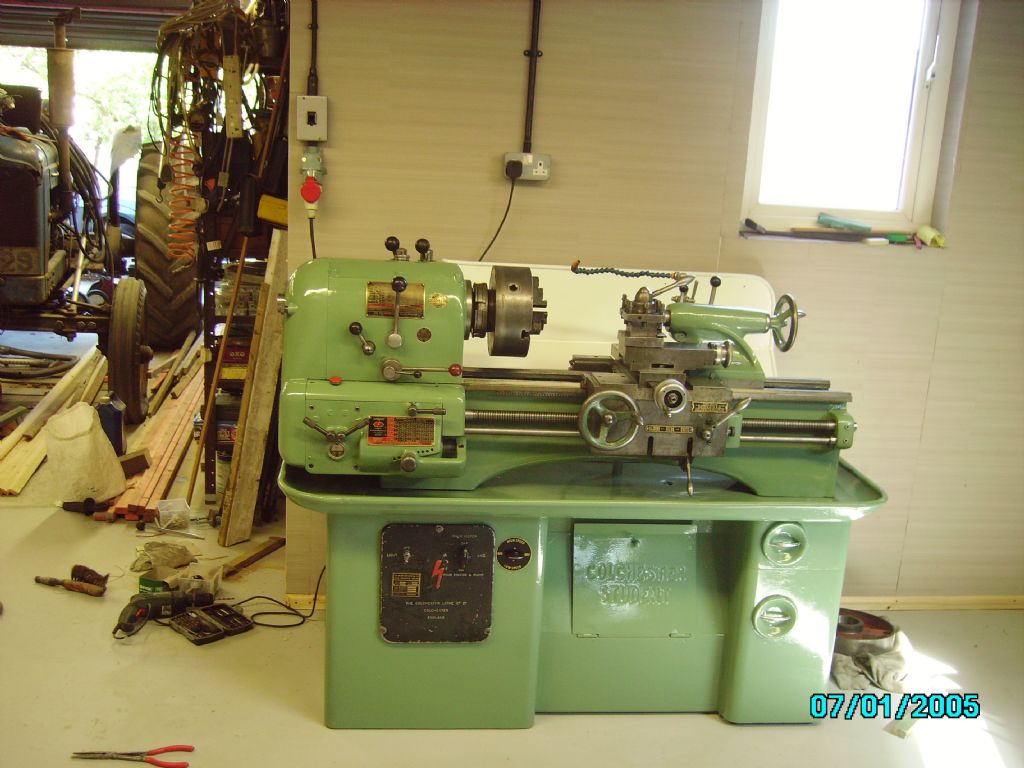
That's the lathe itself, still has a lot of cleaning to be done, but need it working first. As you can see, my forward reverse switch is not original like on your lathe Phil. I'll be able to get more pictures and even videos when i'm back Edited By Richard Kirkman 1 on 27/11/2019 20:07:49 |
| Swarf Maker | 27/11/2019 20:32:39 |
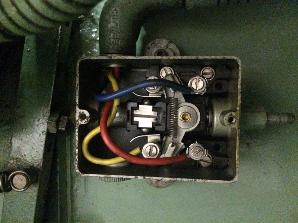
| 132 forum posts 7 photos | Well, I see the nice new cable with its plug going into the big switch box. What I don't see are any wires coming from the output contact set of that switch and into the lathe itself. Are they routed through the backplate of that switch? There is a hole for the wires to come out but nothing visible. |
| Richard Kirkman 1 | 27/11/2019 20:41:30 |
| 334 forum posts 799 photos | Posted by Swarf Maker on 27/11/2019 20:32:39:
Well, I see the nice new cable with its plug going into the big switch box. What I don't see are any wires coming from the output contact set of that switch and into the lathe itself. Are they routed through the backplate of that switch? There is a hole for the wires to come out but nothing visible. Yeah they go out the back into the casing, don't have any pictures of where they go. Not too sure if I even know where they go, but it shall be investigated |
| Phil Whitley | 27/11/2019 20:47:28 |
1533 forum posts 147 photos | Right Richard, that is the same as mine, save for the fact that yours is earlier, and has the flat cast iron gear handles, mine has all rod type handles. The pic of the contactor panel is exactly what I wanted, I will look it over and get back to you, meantime I have messaged you, if you look at the top bar of the page, you will see a little envelope flashing! Your lathe has a hole near to the top right hand corner of the electrical panel, this is where the dual speed motor switch was fitted, I wonder if the motor has been changed? I thought this hole was only drilled when needed, which would indicate that yours was once a dual speed motor. Yours is gap bed, mine is straignt bed, Mine has the two speed motor, and needs new main spindle bearings, which luckily, I have! very original looking machine. We will have it running, one way or another! |
| Phil Whitley | 27/11/2019 21:26:49 |
1533 forum posts 147 photos | Right, there are several areas of the contactor I am not happy with, mainly, as everyone else has noted, the middle of the three contacts appears to be missing, but I can't be sure of that, it may have been modified so that it still works. When I first saw these pics at the top of the post, I thought they were examples of a different lathe, not your actual machine, I see from the ones you have just posted that they are yours. I will pull my control panel tomorrow, and have a look, but I think mine has the later contactor (Crabtree?) fitted. Below the plug in pins on the board, you see three coils, these are the overload tripping coils. the long straight bit of paxolin that goes across the top of all three appears to be a manual reset, you could try pushing it up from the bottom end, where the long arm sticks down, and see if it clicks and closes the overload contacts, may have tripped out if the phase convertor cannot produce enough power for starting. There are various areas on the whole panel that look to be overheating, or have been in the past, and TBH, rather than try to repair it, it would be easier and quicker to take the old contactor off the panel, and replace it with a modern one, keeping all the outside controls as original, but putting new guts inside! having said all this, if two phases are getting to the motor, it should growl and try to turn, and if the contactor is not pulling in, the overloads are irrelevant, as they come after the contactor in the circuit, and the way you have described it, the main contactor is not pulling in anyway. they are LOUD!! Phil |
| Richard Kirkman 1 | 27/11/2019 22:28:11 |
| 334 forum posts 799 photos | Posted by Phil Whitley on 27/11/2019 20:47:28:
Right Richard, that is the same as mine, save for the fact that yours is earlier, and has the flat cast iron gear handles, mine has all rod type handles. The pic of the contactor panel is exactly what I wanted, I will look it over and get back to you, meantime I have messaged you, if you look at the top bar of the page, you will see a little envelope flashing! Your lathe has a hole near to the top right hand corner of the electrical panel, this is where the dual speed motor switch was fitted, I wonder if the motor has been changed? I thought this hole was only drilled when needed, which would indicate that yours was once a dual speed motor. Yours is gap bed, mine is straignt bed, Mine has the two speed motor, and needs new main spindle bearings, which luckily, I have! very original looking machine. We will have it running, one way or another! The picture of the lathe appears to show a hole, but its just a small sticker that has a 1 on it So I'm pretty certain that it has never ever been dual speed. The motor is definitely original too, so I don't think its a possibility. And yes, I watched a video of someone dismantling a similar lathe and repairing it, but the circuitry was different as it was a later model similar to yours. At about 9:10 you can see the inside of his lathe and there is a better video of a crabtree here But, i couldn't really see how it worked compared to my model
|
| Phil Whitley | 28/11/2019 21:14:38 |
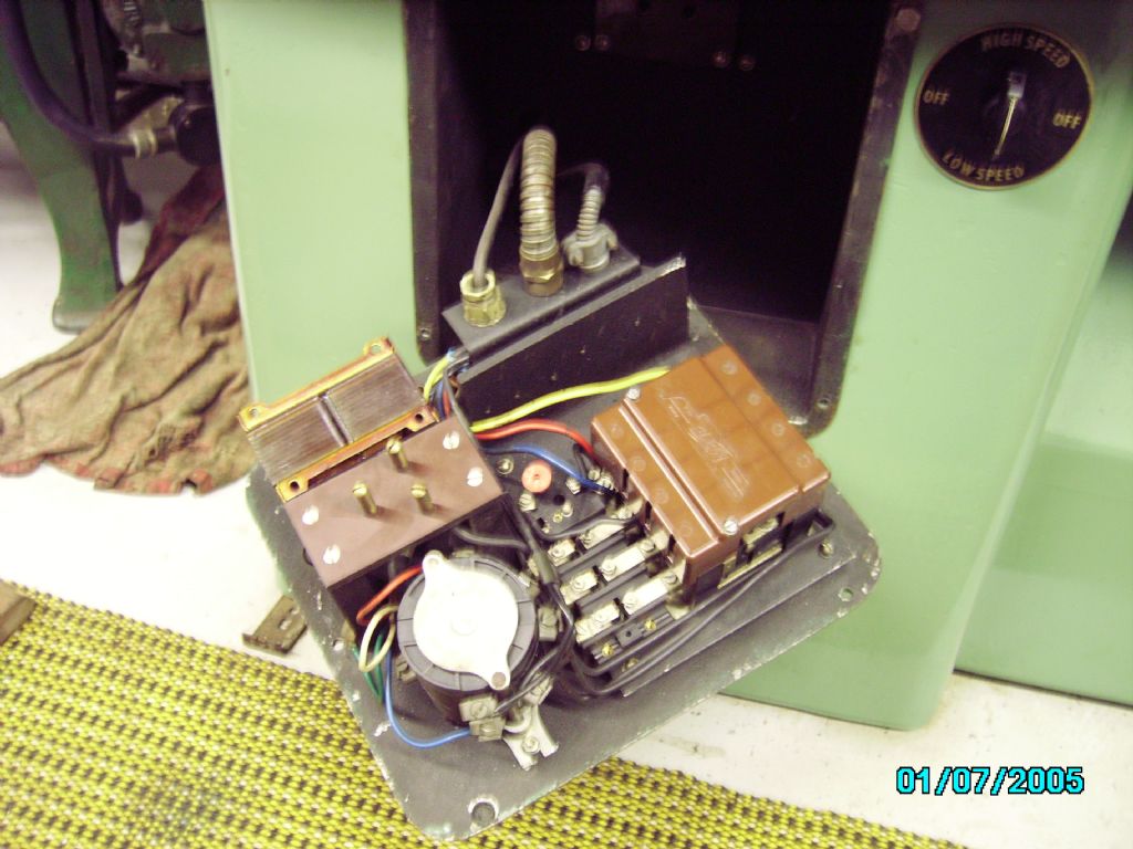
1533 forum posts 147 photos | well richard here is the internals of mine, for what its worth !(not a lot as it is different), the start stop lever does work as I said earlier, if you put power on to the lathe with the start lever in the up position, the pump will run, but the main motor will not, until you press the handle down then lift it up again.
Looking at the pics of your contactor,The three black wires connected to the terminals to the right of the three pin plug, on the overload coils, go to the motor, the three blue wires connected to the other side of the overload coils are the feed from the contactor. You should, with a multimeter, be able to test three seperate phase wires from the isolator switch (check the action of the switch to make sure all three blades are going in to the contacts properly) on the back, through to the three pin socket in the back of the control box, then test from the pinsof the "plug" part to the rotaty switch , out of the switch to the contactor, from the other side of the contactor to the overloads, and then on to the motor, via the reversing switch. The missing contact on the contactor is irrelevant for now, as the contactor is not even pulling in, and it should do this even if it only ends up sending two phases to the motor because of the missing contact. When you have established that three phases are getting to the input side of the contactor, check that you have continuity through the contactors operating coil, and then you will see that one side of the coil is connected directly to a phase and the other end of the coil goes off to the safety switches on the gearbox end cover, and then to the "limit" switch on the back of the headstock, which completes the circuit to pull in the main contactor. Looking at the oily state of the limit switch that could be full of muck and oil, and not making contact, take the lid off and check it, I am going to try to post up the wiring diagram from my lathe, although the contactors are different, they are electrically identical, and this diagram is somewhat easier to read and understand.
Phil |
| Richard Kirkman 1 | 29/11/2019 00:01:16 |
| 334 forum posts 799 photos | Posted by Phil Whitley on 28/11/2019 21:14:38:
well richard here is the internals of mine, for what its worth !(not a lot as it is different), the start stop lever does work as I said earlier, if you put power on to the lathe with the start lever in the up position, the pump will run, but the main motor will not, until you press the handle down then lift it up again.
Looking at the pics of your contactor,The three black wires connected to the terminals to the right of the three pin plug, on the overload coils, go to the motor, the three blue wires connected to the other side of the overload coils are the feed from the contactor. You should, with a multimeter, be able to test three seperate phase wires from the isolator switch (check the action of the switch to make sure all three blades are going in to the contacts properly) on the back, through to the three pin socket in the back of the control box, then test from the pinsof the "plug" part to the rotaty switch , out of the switch to the contactor, from the other side of the contactor to the overloads, and then on to the motor, via the reversing switch. The missing contact on the contactor is irrelevant for now, as the contactor is not even pulling in, and it should do this even if it only ends up sending two phases to the motor because of the missing contact. When you have established that three phases are getting to the input side of the contactor, check that you have continuity through the contactors operating coil, and then you will see that one side of the coil is connected directly to a phase and the other end of the coil goes off to the safety switches on the gearbox end cover, and then to the "limit" switch on the back of the headstock, which completes the circuit to pull in the main contactor. Looking at the oily state of the limit switch that could be full of muck and oil, and not making contact, take the lid off and check it, I am going to try to post up the wiring diagram from my lathe, although the contactors are different, they are electrically identical, and this diagram is somewhat easier to read and understand.
Phil Thanks Phil, I think I'm starting to understand a bit the stuff you're saying. I've responded to your message, so there should be something in your inbox. Thanks |
| Phil Whitley | 04/12/2019 20:39:11 |
1533 forum posts 147 photos | Moderators! can you move these pics 90 deg to the right please!
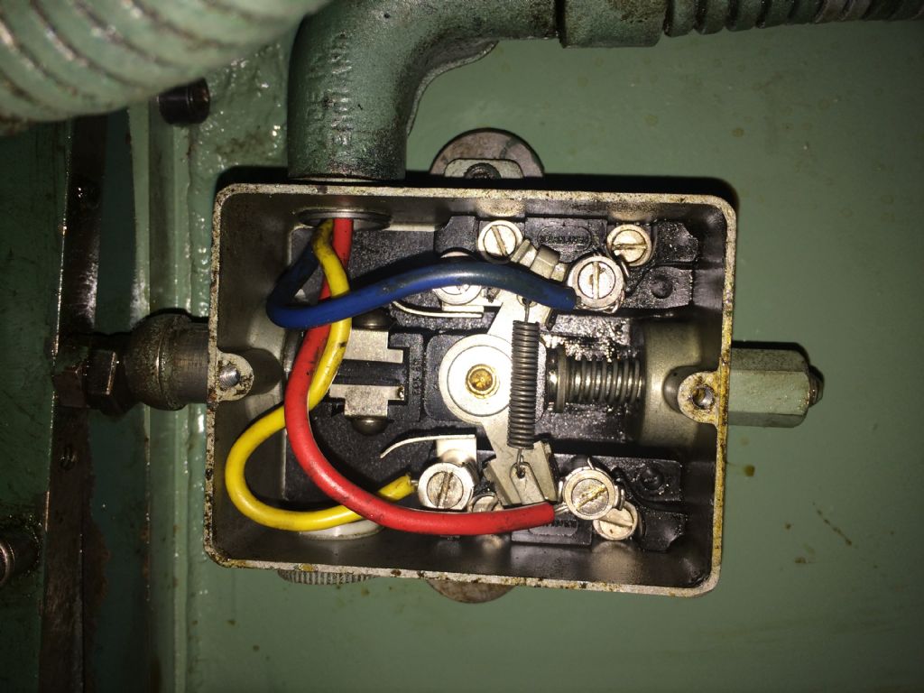
some pics of the inside of the "limit" switch which is used as the start/stop switch on the student. First in the OFF position
And in the ON position
Off connects the red to the blue, and on connects the yellow to the blue, both contacts on the blue side of the switch are linked. the problem we have here is trying to reproduce the wiring diagram, as ALL the manuals I have looked at so far have small diagrams that will not enlarge without loss of print quality, and also some badly printed with wires that fade out to nothing! Making it work is easy for a sparky, but I want to reproduce a wiring diagram that shows the factory wiring, as this is what Richard has to deal with, I will soldier on, but if anyone has a copy of the wiring diagram without printing flaws, and of a reasonable readable size, post it up!! The basic contactor/switching arrangement is all there, but the safety/NVR circuit has bits missing on all the diagrams I can find |
| Phil Whitley | 05/12/2019 14:40:50 |
1533 forum posts 147 photos | Hold the bus!! I have just looked at the PDF of a Colchester Clausing manual, which states that the limit switch has THREE positions, and having now tested mine, find this is correct! there is an intermediate position where the red and blue remain connected together till the handle moves past the mid position, and the overcentre spring mechanism jumps from the bottom pair of contacts to the top pair (see pics above, which need rotating 90 deg) The clausing manual has a better wiring diagram, but I need to check out some of the none SI symbols to confirm it is the same. Phil |
| Richard Kirkman 1 | 07/12/2019 13:53:16 |
| 334 forum posts 799 photos | Posted by Phil Whitley on 05/12/2019 14:40:50:
Hold the bus!! I have just looked at the PDF of a Colchester Clausing manual, which states that the limit switch has THREE positions, and having now tested mine, find this is correct! there is an intermediate position where the red and blue remain connected together till the handle moves past the mid position, and the overcentre spring mechanism jumps from the bottom pair of contacts to the top pair (see pics above, which need rotating 90 deg) The clausing manual has a better wiring diagram, but I need to check out some of the none SI symbols to confirm it is the same. Phil So what does each position do to the circuit. It's the part from the no volt release sort of bit, the ring with the key and cover and stuff, so is the intermediate position where we lifted the handle and it only beeped for a second and stopped after the handle was raised further? Also, I've sent my flatmate back to Driffield with something I've made for you. Nothing too special, but you can always heat your workshop with it if not. Thanks |


Please login to post a reply.
Magazine Locator
Want the latest issue of Model Engineer or Model Engineers' Workshop? Use our magazine locator links to find your nearest stockist!
Sign up to our Newsletter
Sign up to our newsletter and get a free digital issue.
You can unsubscribe at anytime. View our privacy policy at www.mortons.co.uk/privacy
Latest Forum Posts
- *Oct 2023: FORUM MIGRATION TIMELINE*
05/10/2023 07:57:11 - Making ER11 collet chuck
05/10/2023 07:56:24 - What did you do today? 2023
05/10/2023 07:25:01 - Orrery
05/10/2023 06:00:41 - Wera hand-tools
05/10/2023 05:47:07 - New member
05/10/2023 04:40:11 - Problems with external pot on at1 vfd
05/10/2023 00:06:32 - Drain plug
04/10/2023 23:36:17 - digi phase converter for 10 machines.....
04/10/2023 23:13:48 - Winter Storage Of Locomotives
04/10/2023 21:02:11 - More Latest Posts...
- View All Topics
Support Our Partners


Shopping Partners
Subscription Offer

Latest "For Sale" Ads
- Reeves** - Rebuilt Royal Scot by Martin Evans
by John Broughton
£300.00 - BRITANNIA 5" GAUGE James Perrier
by Jon Seabright 1
£2,500.00 - Drill Grinder - for restoration
by Nigel Graham 2
£0.00 - WARCO WM18 MILLING MACHINE
by Alex Chudley
£1,200.00 - MYFORD SUPER 7 LATHE
by Alex Chudley
£2,000.00 - More "For Sale" Ads...
Latest "Wanted" Ads
- D1-3 backplate
by Michael Horley
Price Not Specified - fixed steady for a Colchester bantam mark1 800
by George Jervis
Price Not Specified - lbsc pansy
by JACK SIDEBOTHAM
Price Not Specified - Pratt Burnerd multifit chuck key.
by Tim Riome
Price Not Specified - BANDSAW BLADE WELDER
by HUGH
Price Not Specified - More "Wanted" Ads...
Get In Touch!
Do you want to contact the Model Engineer and Model Engineers' Workshop team?
You can contact us by phone, mail or email about the magazines including becoming a contributor, submitting reader's letters or making queries about articles. You can also get in touch about this website, advertising or other general issues.
Click THIS LINK for full contact details.
For subscription issues please see THIS LINK.
Digital Back Issues


Donate

 Register
 Log-in
Model Engineer Magazine
- Percival Marshall
- M.E. History
- LittleLEC
- M.E. Clock

ME Workshop
- An Adcock
- & Shipley
- Horizontal
- Mill

Subscribe Now
- Great savings
- Delivered to your door

Pre-order your copy!
- Delivered to your doorstep!
- Free UK delivery!
All Forum Topics > Help and Assistance! (Offered or Wanted) > Colchester Student Mk1 Won't Start