Forum sponsored by:

The Workshop Progress Thread 2019
| martin perman | 17/01/2019 20:59:49 |
 2095 forum posts 75 photos | Jason, I can only describe that engine as beautiful, does the screen cooling work as well and how much time did you take timing the ignition trips, I've watched owners of full size engines spend ages trying to get full size ones working properly, Vanderoot verticals are few and far between in the uk but there are a lot of open crank horizontals about. Finally was it a set of castings or made from scratch. Martin P
|
| Ron Laden | 17/01/2019 21:50:15 |
 2320 forum posts 452 photos | Oh I really do like that and some lovely engineering, did you cut all those corner joints on the wooden box by hand. You know me Jason, what type of engine is it, how does it work and Martin mentions screen cooling..? Excellent. |
| martin perman | 17/01/2019 22:05:12 |
2095 forum posts 75 photos | Ron, Screen cooling was a method favoured by the Americans to cool the engine water, the pump that the engine is driving pumps the water through the engine and it comes out of the pipe at the top of the cone in a spray pattern down the screen, because of the surface area and the surrounding air it cools the water which collects in the tank at the bottom to go around again, engilsh manufacturers tended to rely on large tanks of water which evaporated off the heat. As its Jasons engine I will let him describe how it works. Martin P Edited By martin perman on 17/01/2019 22:06:39 |
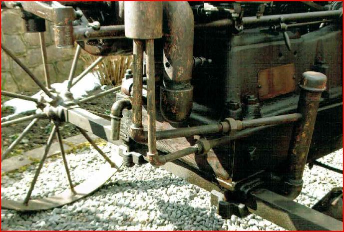
| JasonB | 18/01/2019 07:59:01 |
 25215 forum posts 3105 photos 1 articles | Martin, I have spent a lot of time fiddling with the ignitor trip, it does not have the same adjustment methods as some or the horizontals that I have built so is a right pig to get working anywhere near right. The pump does work when I have tried it with a cordless drill, may hook it up and run some water through it once the engine is running well though they don't get too hot and can be run for several minutes dry. It is from a casting kit but the cart is scratch built. It came to me as part made with all the larger items having been done, there were some major issues such as a wonky crankshaft and the top of the crankcase was machined very out of true so the cylinder was leaning sideways Ron, this is how I did the joints. The engine would be classed as a Vertical Hit & Miss Engine. vertical as it stands upright rather than the more common layout with a horizontal cylinder. The hit and miss bit refers to how the speed is controlled (not set working in that video) There is a pivoting weight on the inside of the flywheel that swings out as the engines speed increases, as it rotates round it pushes a lever that will latch the exhaust pushrod in the open position which means there will be no compression and the engine won't fire which is the miss part. As the speed drops the latch will release and close off the exhaust so the engine will then be able to draw in air/fuel as there will be a vacuum when the piston goes down - compressed - fire which is the hit part. When the engine is running under load it may not get up to a fast enough speed to miss so will fire on each stroke, if the load is taken off then it will start to miss. If you watch my video of it's stable mate you can see that the exhaust rocker arm only lifts clear of the valve about every 3rd or 4th cycle. Otherwise it is just a 4-stroke engine, the only slight difference is that the inlet valve does not have a mechanical opening such as push rod and rocker. It just has a weak spring which is just enough to hole the vale closed but on the intake stroke the vacuum in the cylinder will open the valve letting the air/fuel mix in. As the carb is at the top of the engine this one also has a fuel pump down on the left hand side - the whole bottom casting is the fuel tank - which constantly pumps fuel to the carb with any excess flowing back down to the tank under gravity. It does not use a spark plug but has what is known as an ignitor. Basically a set of moving contacts that are within the head. As the exhaust pushrod moves up it has a lever on the side which closes the contacts and allows electricity from the battery to flow around a circuit containing a low tension coil. As the rod goes up more it moves away from the ignitor and allows the contacts to open but the energy in the coil causes a spark to jump across the gap and this is what ignites the fuel. They are very tricky to make with lots of small parts and torsion springs to be wound. As said by Martin cooling is buy water being pumped into the bottom of a water space around the cylinder then into voids in the head before overflowing down the wire mesh which cools the water before it gets pumped round again. J |
| Ron Laden | 18/01/2019 09:17:22 |
2320 forum posts 452 photos | Posted by JasonB on 18/01/2019 07:59:01:
Martin, I have spent a lot of time fiddling with the ignitor trip, it does not have the same adjustment methods as some or the horizontals that I have built so is a right pig to get working anywhere near right. The pump does work when I have tried it with a cordless drill, may hook it up and run some water through it once the engine is running well though they don't get too hot and can be run for several minutes dry. It is from a casting kit but the cart is scratch built. It came to me as part made with all the larger items having been done, there were some major issues such as a wonky crankshaft and the top of the crankcase was machined very out of true so the cylinder was leaning sideways Ron, this is how I did the joints. The engine would be classed as a Vertical Hit & Miss Engine. vertical as it stands upright rather than the more common layout with a horizontal cylinder. The hit and miss bit refers to how the speed is controlled (not set working in that video) There is a pivoting weight on the inside of the flywheel that swings out as the engines speed increases, as it rotates round it pushes a lever that will latch the exhaust pushrod in the open position which means there will be no compression and the engine won't fire which is the miss part. As the speed drops the latch will release and close off the exhaust so the engine will then be able to draw in air/fuel as there will be a vacuum when the piston goes down - compressed - fire which is the hit part. When the engine is running under load it may not get up to a fast enough speed to miss so will fire on each stroke, if the load is taken off then it will start to miss. If you watch my video of it's stable mate you can see that the exhaust rocker arm only lifts clear of the valve about every 3rd or 4th cycle. Otherwise it is just a 4-stroke engine, the only slight difference is that the inlet valve does not have a mechanical opening such as push rod and rocker. It just has a weak spring which is just enough to hole the vale closed but on the intake stroke the vacuum in the cylinder will open the valve letting the air/fuel mix in. As the carb is at the top of the engine this one also has a fuel pump down on the left hand side - the whole bottom casting is the fuel tank - which constantly pumps fuel to the carb with any excess flowing back down to the tank under gravity. It does not use a spark plug but has what is known as an ignitor. Basically a set of moving contacts that are within the head. As the exhaust pushrod moves up it has a lever on the side which closes the contacts and allows electricity from the battery to flow around a circuit containing a low tension coil. As the rod goes up more it moves away from the ignitor and allows the contacts to open but the energy in the coil causes a spark to jump across the gap and this is what ignites the fuel. They are very tricky to make with lots of small parts and torsion springs to be wound. As said by Martin cooling is buy water being pumped into the bottom of a water space around the cylinder then into voids in the head before overflowing down the wire mesh which cools the water before it gets pumped round again. J Thanks Jason, That is fascinating and different too, I am really impressed with it I could sit and watch it run for ages. I can see what you mean about tricky to make with all those small parts and I can imagine it taking some time and effort to set up. I see from the link that it runs on gas, is that always the case or can they run on other fuel, I was assuming yours was running on petrol. I have learnt something in using a slot drill to cut wood, again I would have assumed that wood cutting bits have to be used, thats good to know. Which wood did you make the box from Jason, is it oak.? Very impressive, great stuff. Ron |
| martin perman | 18/01/2019 09:27:10 |
2095 forum posts 75 photos | Jason, You said that you made the trolley from scratch, did you look at pictures as its a very good approximation of an Amanco engine trolley particularly the wheels, Amanco wheels were fabricated. Martin P Edited By martin perman on 18/01/2019 09:27:44 |
| JasonB | 18/01/2019 11:05:31 |
25215 forum posts 3105 photos 1 articles | Ron, In America it is a gas engine as that is what they call petrol. It is designed to run on petrol or as a lot of us do it can be run on what the Americans call "white gas" which is a liquid fuel commonly used for camping stoves etc and goes by the name of "Colmans Fuel". The main advantage is it does not smell like petrol so if you keep your models indoors they don't stink the house down, the exhaust fumes are not as bad either. You can also use some of the "Green" fuels for lawnmowers etc such as Aspen. Yes European oak. Martin, if you look back at earlier posts in the thread I linked to about making the box I have gone into a bit more detail about the carts and their construction. They are probably both a bit big for these small engines but I was asked to see if I could do them to match some photos, this is what the vertical one is based on.
I did similar with my 1/3rd scale galloway basing the cart on some photos from a US e-bay advart that had a few sizes that made scaling it easier. I do have a set of castings for an Associated Hired Man but that will be a very small barrow type cart. Edited By JasonB on 18/01/2019 11:08:49 |
| Ron Laden | 18/01/2019 16:34:41 |
2320 forum posts 452 photos | Posted by JasonB on 18/01/2019 11:05:31:
Ron, In America it is a gas engine as that is what they call petrol. It is designed to run on petrol or as a lot of us do it can be run on what the Americans call "white gas" which is a liquid fuel commonly used for camping stoves etc and goes by the name of "Colmans Fuel". The main advantage is it does not smell like petrol so if you keep your models indoors they don't stink the house down, the exhaust fumes are not as bad either. You can also use some of the "Green" fuels for lawnmowers etc such as Aspen. Yes European oak. Martin, if you look back at earlier posts in the thread I linked to about making the box I have gone into a bit more detail about the carts and their construction. They are probably both a bit big for these small engines but I was asked to see if I could do them to match some photos, this is what the vertical one is based on.
I did similar with my 1/3rd scale galloway basing the cart on some photos from a US e-bay advart that had a few sizes that made scaling it easier. I do have a set of castings for an Associated Hired Man but that will be a very small barrow type cart. Edited By JasonB on 18/01/2019 11:08:49 Jason, I was forgetting I was looking at an American site and when I read gas or propane I didnt make the connection between gas and petrol. I have just finished reading through your link to "the cart" and I have to take my hat off to you, that for me was something of a master class in model engineering. The thought, the approach, the design let alone the skill and craftmanship that went into it I thought was inspiring. Someone commented "you make it all look so easy" and I think that speaks volumes Jason. Ron |
| martin perman | 18/01/2019 18:12:40 |
2095 forum posts 75 photos | I've spent a couple of days this week sorting out my powersaw, a new motor, new drive belt and a complete rewire which gave me a nasty surprise. I took the switch apart to find no form of cable clamp for either the power in or the power out to the motor, the power in earth was connected to the center of three contacts but the power out was connected to the switch frame so no connected earth, these were soon put right. I then cut a piece of 22mm steel measured its thickness and tinkered with the saw blade supports and manage to get another piece cut with only an error of 0.1mm difference in thickness, I think I will leave it at that, not bad for an old machine that I was given at least six years ago in a sorry state. Martin P Edited By martin perman on 18/01/2019 18:14:02 |
| Joseph Noci 1 | 18/01/2019 18:34:21 |
| 1323 forum posts 1431 photos | Jason, that is really superb work with excellent detail. Very well done indeed! Really good to watch the talents abound in these groups. Well Done! I have finally succumbed and am going to cease making tools and machines for a while and try a long time fascination - a Stirling engine. There is just such a massive onslaught of info on Stirling engines on the web that after many many hours of googling, I have no idea where to start! Your posts are inspirational.. Joe |
| Johnboy25 | 18/01/2019 20:32:09 |
 260 forum posts 3 photos | Started the Year New well by making the rear leaf springs for my GWR 16xx. I’ve located a supplier of spring steel strip which I’ve rolled to the curvature needed for the spring sets. Now I have to research heat treating & tempering as I haven’t made leaf springs before. 😳 Some experimenting & trials before I attempt the leaf springs! (Any advice welcomed) I’ve also started the pipework for the loco. Set myself an optimistic target to get the engine in steam by the end of February 2019🤔 John |
| Ian McVickers | 18/01/2019 20:51:06 |
| 261 forum posts 117 photos |
Managed to get some more done to the universal head upgrade.
Added locating bar to the base plate so that it slots snugly in the t slot on the table.
Upper part nearly done apart from engraving the degrees scale. The 40mm indexable head I have didn't leave a great finish so I will give it a rub down when everything else is complete.
All parts fitted together to see how it looks on the tool grinder and so far so good.
|
| Ron Laden | 19/01/2019 07:26:26 |
2320 forum posts 452 photos | Jason, Do you have any video of the Galloway engine running, I would like to watch that if you have any footage Ron |
| JasonB | 19/01/2019 09:27:24 |
25215 forum posts 3105 photos 1 articles | I'm up at Alley Pally so will post a link later. Or if you view one of the above videos on YouTube you can look at my channel, Galloway is towards the bottom. Also worth looking at the Monitor and Gade which show the governors latching as the should. |
| Ron Laden | 19/01/2019 15:46:37 |
2320 forum posts 452 photos | Oops sorry Jason, didnt realise you are at the exhibition. Watched the Galloway video, very nice and I was surprised how quick it runs it gets quite a lick on. Also watched the Monitor and Gade and see what you mean about the governors you can see them operating quite clearly. Ron |
| Ron Laden | 19/01/2019 19:57:45 |
2320 forum posts 452 photos | Jason, out of interest a couple of questions from the cart build and the wheels. When you cut the centres from the steel discs was the tool a parting tool, cant quite see the tip in the photo. Also when turning the radius on the hubs, is the ball cutter you used your own design and build. Ron |
| JasonB | 19/01/2019 20:13:06 |
25215 forum posts 3105 photos 1 articles | It's what is commonly known as a trepanning tool, much like a parting tool but one edge needs extra clearance so it won't rub on the outside edge of the groove being cut.
I made the ball turner but it is more or less to the Steve Bedair design, if you google "bedair ball turner" you should find drawings. |
| John Haine | 20/01/2019 10:11:37 |
| 5563 forum posts 322 photos | Having lugged 7 bags of sugar (or its equivalent in cast iron bar) home from Ally Pally for my Synchronome bob I needed to at least square off the ends and drill for the rod. I did't fancy trying to mount it in the lathe - 7 inches long and over 3 diameter and weighing that much, and not able to use a fixed steady on the as-cast circumference. Only option was the mill, I decided what I really needed was a very large Keats angle plate but no idea where to get such a thing. So dtarted to look at my collection of angle plates and found this one:
Bought for a pittance from a market stall years ago, it's ground square on the inside edges as well as the outside and ends. Work of a few moments to clamp to the mill table.
That's the bob sitting on the swarf tray btw.
Couple of G clamps to pull the cylindrical surface against the faces of the angle plate and "Bob's your uncle" you might say. |
| JasonB | 21/01/2019 18:19:22 |
25215 forum posts 3105 photos 1 articles | Spent yesterdays workshop time winding rotary table handles to turn a couple of bits of 5mm thick aluminium into sawrf, I did find these two parts left in the pile and think they may do as cylinder supports for my Forest styled flame licker.
|
| Ron Laden | 21/01/2019 20:27:37 |
2320 forum posts 452 photos | Nice Jason, they must have taken quite a lot of re positioning as there is a number of radii in them, no five minute job I would have thought. |


This thread is closed.
Magazine Locator
Want the latest issue of Model Engineer or Model Engineers' Workshop? Use our magazine locator links to find your nearest stockist!
Sign up to our Newsletter
Sign up to our newsletter and get a free digital issue.
You can unsubscribe at anytime. View our privacy policy at www.mortons.co.uk/privacy
Latest Forum Posts
- hemingway ball turner
04/07/2025 14:40:26 - *Oct 2023: FORUM MIGRATION TIMELINE*
05/10/2023 07:57:11 - Making ER11 collet chuck
05/10/2023 07:56:24 - What did you do today? 2023
05/10/2023 07:25:01 - Orrery
05/10/2023 06:00:41 - Wera hand-tools
05/10/2023 05:47:07 - New member
05/10/2023 04:40:11 - Problems with external pot on at1 vfd
05/10/2023 00:06:32 - Drain plug
04/10/2023 23:36:17 - digi phase converter for 10 machines.....
04/10/2023 23:13:48 - More Latest Posts...
- View All Topics
Support Our Partners


Shopping Partners
Subscription Offer

Latest "For Sale" Ads
- Reeves** - Rebuilt Royal Scot by Martin Evans
by John Broughton
£300.00 - BRITANNIA 5" GAUGE James Perrier
by Jon Seabright 1
£2,500.00 - Drill Grinder - for restoration
by Nigel Graham 2
£0.00 - WARCO WM18 MILLING MACHINE
by Alex Chudley
£1,200.00 - MYFORD SUPER 7 LATHE
by Alex Chudley
£2,000.00 - More "For Sale" Ads...
Latest "Wanted" Ads
- D1-3 backplate
by Michael Horley
Price Not Specified - fixed steady for a Colchester bantam mark1 800
by George Jervis
Price Not Specified - lbsc pansy
by JACK SIDEBOTHAM
Price Not Specified - Pratt Burnerd multifit chuck key.
by Tim Riome
Price Not Specified - BANDSAW BLADE WELDER
by HUGH
Price Not Specified - More "Wanted" Ads...
Get In Touch!
Do you want to contact the Model Engineer and Model Engineers' Workshop team?
You can contact us by phone, mail or email about the magazines including becoming a contributor, submitting reader's letters or making queries about articles. You can also get in touch about this website, advertising or other general issues.
Click THIS LINK for full contact details.
For subscription issues please see THIS LINK.
Digital Back Issues


Donate

 Register
 Log-in
Model Engineer Magazine
- Percival Marshall
- M.E. History
- LittleLEC
- M.E. Clock

ME Workshop
- An Adcock
- & Shipley
- Horizontal
- Mill

Subscribe Now
- Great savings
- Delivered to your door

Pre-order your copy!
- Delivered to your doorstep!
- Free UK delivery!
All Forum Topics > Work In Progress and completed items > The Workshop Progress Thread 2019