Forum sponsored by:

John Wilding 8 day Weight Driven Wall Clock
Help
| Alan Charleston | 07/01/2017 05:31:27 |
| 157 forum posts 26 photos | Thanks for the link to Cobb's site. My problem is that I am in New Zealand so getting stuff here could be expensive and slow. Alan C. |
| Alan Charleston | 12/02/2017 00:42:12 |
| 157 forum posts 26 photos | Hi, I wonder if someone can help me with the pallets for this blasted clock. The method for marking them out using a depthing tool shown in Wilding's book is too complicated for me so I have been trying to simulate his method using a drawing program to generate a paper pattern I can glue onto the carbon steel blank. The problem I have struck is trying to understand the situation shown in drawing 2. As I understand it, the pallets are supposed to cover 71/2 teeth on the escape wheel. As far as I can see from drawing 2, the pallets cover 8 teeth and appear to lock the escape wheel so it can't move. Any help will be gratefully received.
|
| Bob Stevenson | 12/02/2017 09:02:15 |
| 579 forum posts 7 photos | The pallets DO space across 7 1/2 teeth but this is just the usual poor quality of JW writings.......... Cut out the escape wheel and loosely nail/pin it vertically, then make a set of pallets from a piece of tin plate and nail that up too,..then have a play of the action and you will soon get the idea. Once you have a nicely working tin plate model you can use that as the template to cut out/file up the real thing. |
| RJW | 12/02/2017 09:55:22 |
| 343 forum posts 36 photos | Alan, the drawing in photo 2 is to show how to generate the shape of the pallets, which are actually shown in mid position (pendulum mid swing (vibration) and the escape wheel is actually locked at that point, although there would in reality be a small degree of clearance between the wheel teeth and pallets at this point, There are several animations listed and linked on the site if you go to the homepage, John. Edited to get rid of a smiley? Edited By RJW on 12/02/2017 09:57:18 |
| Bizibilder | 12/02/2017 10:15:08 |
 173 forum posts 8 photos | The Pallet nibs are deliberately drawn and cut out very slightly oversize (as stated in the book). The pallet will not work to start with but as you refine the pallet action it is necessary to file away a tiny bit on each pallet nib in order to get them to work. You do this without changing the depthing. |
| roy entwistle | 12/02/2017 11:31:11 |
| 1716 forum posts | As Bizibilder Says, work on the pallet nibs but remember to work on right hand side of each nib only as drawn in 2 above |
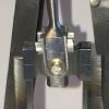
| Stephen Benson | 12/02/2017 11:50:54 |
 203 forum posts 69 photos | This how I did my JW 8 day clock pallets, it was a long time ago now but the clock is still running well so I must of got something right
|
| Alan Charleston | 12/02/2017 21:45:33 |
| 157 forum posts 26 photos | Thanks for the help. One of the problems I struck was that the book says that the line GH shown in drawing 2 should pass through C and between F and D. It doesn't specify how it should pass between F and D. I have therefore drawn GH such that it passes through a point midway between F and D and generated a drawing of the pallets which I have printed and glued to a piece of 1/16" brass. I'll follow Bob Stevensons advice and see how I get on. Thanks again, Alan |
| Alan Charleston | 15/03/2017 06:27:45 |
| 157 forum posts 26 photos | Hi, After waiting for weeks my 0.2mm slitting saw finally turned up so I have been able to cut the slots required to get the pendulum installed. It's amazing how the suspension spring lets the pendulum oscillate for a couple of hours when it's set in motion. I now need to install the crutch. The book gives the dimension of the slot which goes around the upper block as 3/16" which is the same as the upper block. In my case, this has resulted in a tight fit. Am I right in thinking that it should be a loose fit with the slop taken up by the adjustable shim? If so I'll file the crutch slot out. Does anyone have any photos of the way the upper block fits into the crutch? I've made the pallets, so once I've got the crutch sorted out I can look at putting everything together and see if it ticks. Exciting times indeed! Regards, Alan C. |
| Stephen Benson | 15/03/2017 14:08:58 |
203 forum posts 69 photos | You need about 0.1mm (4thou) minimum clearance on the block just file it as it is not very critical but both the slot and block need to be polished, I made mine adjustable because I did not know any better but since then I have seen longcase clocks working well with twice that clearance, too big is better than too small. |
| Alan Charleston | 15/03/2017 22:43:08 |
| 157 forum posts 26 photos | Thanks Stephen - Just what I wanted to know. Regards, Alan |
| Russell Eberhardt | 16/03/2017 10:07:33 |
 2785 forum posts 87 photos | Posted by Alan Charleston on 15/03/2017 06:27:45:It's amazing how the suspension spring lets the pendulum oscillate for a couple of hours when it's set in motion.
Yes, nearly 99% of the energy loss in a free swinging pendulum like that is due to air resistance. The way to measure the Q (quality) factor of a pendulum is to set it swinging at a measured amplitude. Time how long it takes to decay to 37% of that amplitude. You can then work out the number of swings it has made. The Q is then given by Q = 2 x pi x n where n is the number of complete swings (2 seconds for a seconds pendulum!). A good longcase clock pendulum should have a Q factor near to 10,000. Russell |
| Alan Charleston | 17/03/2017 06:09:12 |
| 157 forum posts 26 photos | Hi Russell, Thanks for that. Just to clarify, does the Q factor of 10,000 applies to the pendulum alone - without the crutch? Also, pardon my ignorance, but is the amplitude the horizontal distance the pendulum travels or is it the angle it moves through? Another couple of extra questions, I have had the pendulum oscillating with the crutch and pallets operating the freewheeling escape wheel. The pallets made the escape wheel rotate backwards. Does this mean I've got the pallets about right? I haven't attached the wheels to their shafts yet. John Wilding recommends Loctiting them in place but I think I would prefer to slit the arbors and fit collets to compress them onto the shafts as he recommends for attaching the crutch to its' shaft. I can then adjust them to where I want them to sit easily. Is there any reason why I shouldn't do this? Thanks again, Alan C. |
| Stephen Benson | 17/03/2017 08:07:19 |
203 forum posts 69 photos | I used Loctite 638 retainer and continue to use, Loctite is not permanent if you heat it up with a flame it will release easily I often loctite milling cutters into bespoke holders they will take a full cut but you can replace them when they wear out. Adding weight to the train should be avoided but on this clock there is loads of spare power so it should not be a problem. |
| roy entwistle | 17/03/2017 08:51:39 |
| 1716 forum posts | Alan C From what you say I would suggest you have a good chance of your pallets being very near I would also Loctite the other wheels to the arbors Roy |
| Russell Eberhardt | 17/03/2017 11:12:02 |
2785 forum posts 87 photos | Alan, The amplitude can be either the linear or the angular displacement. For small angles (say less than 5 deg) they are linearly related. The Q factor of the pendulum is for the pendulum and suspension alone. You shouldn't let it swing connected to the escapement with no drive on the clock. You run the risk of the pallet hitting the tip of an escape wheel tooth and damaging it. However it sounds as if yours is OK. I also use Loctite 638 but do be sure that you degrease thoroughly beforehand. If the adhesive lets go in use the weight will descend at high speed and can damage the mechanism as a result. The crutch needs to be adjustable to put the clock in beat. Russell. |
| Jim C | 17/03/2017 13:50:01 |
 76 forum posts 4 photos | Hi, On the subject of Loctite. I have bought the pinions for this clock (not having made the lantern ones described in the build notes) and as a consequence they do not have shoulders for connection to their respective wheel. Do you think that Loctite will be adequate to fix the wheel and pinion to the arbor or will some pinning need to be done? (not much room in the pinion for this). Any suggestions gratefully received. Thanks, Jim |
| Russell Eberhardt | 17/03/2017 14:37:13 |
2785 forum posts 87 photos | The traditional way of fixing a pinion direct to a wheel would be to turn a shoulder on the end of the pinion to be a tight fit in the wheel bore and a about 10 thou longer than the thickness of the wheel. The pinion is then pressed into the wheel and the protruding part opened out with a conical punch. An alternative is to use a star shaped punch which gives a somewhat more secure fixing. You do have to be careful to maintain cocentricity. Russell. |
| Alan Charleston | 19/03/2017 05:37:34 |
| 157 forum posts 26 photos | Thanks for all the comments. I'll follow the advice and Loctite the wheels in place. It's interesting the general opinion favours using Loctite 638. Wilding recommends 601 in the book - but that is more than 25 years old now, so I'll go for the 638. I'm worried about using Loctite as I've had problems in the past when I've mucked about too long getting the position right and having a piece freeze in the wrong position. I think I'll make a 1/2" OD/ 3/32" ID collet bored out to say 1/4" 6mm from one end and use this to position the wheel on the shaft before adding the Loctite. I can then apply the glue to the shaft and slide the wheel into position up against the collet with no delays. The bored out end will stop the wheel sticking to the collet. Regards, Alan C. |
| roy entwistle | 19/03/2017 09:40:01 |
| 1716 forum posts | I wouldn't Loctite the wheel to the pinion. If there is room I would make a collet for the wheel and fasten that to the arbor at the side of the pinion Roy |


Please login to post a reply.
Magazine Locator
Want the latest issue of Model Engineer or Model Engineers' Workshop? Use our magazine locator links to find your nearest stockist!
Sign up to our Newsletter
Sign up to our newsletter and get a free digital issue.
You can unsubscribe at anytime. View our privacy policy at www.mortons.co.uk/privacy
Latest Forum Posts
- *Oct 2023: FORUM MIGRATION TIMELINE*
05/10/2023 07:57:11 - Making ER11 collet chuck
05/10/2023 07:56:24 - What did you do today? 2023
05/10/2023 07:25:01 - Orrery
05/10/2023 06:00:41 - Wera hand-tools
05/10/2023 05:47:07 - New member
05/10/2023 04:40:11 - Problems with external pot on at1 vfd
05/10/2023 00:06:32 - Drain plug
04/10/2023 23:36:17 - digi phase converter for 10 machines.....
04/10/2023 23:13:48 - Winter Storage Of Locomotives
04/10/2023 21:02:11 - More Latest Posts...
- View All Topics
Support Our Partners


Shopping Partners
Subscription Offer

Latest "For Sale" Ads
- Reeves** - Rebuilt Royal Scot by Martin Evans
by John Broughton
£300.00 - BRITANNIA 5" GAUGE James Perrier
by Jon Seabright 1
£2,500.00 - Drill Grinder - for restoration
by Nigel Graham 2
£0.00 - WARCO WM18 MILLING MACHINE
by Alex Chudley
£1,200.00 - MYFORD SUPER 7 LATHE
by Alex Chudley
£2,000.00 - More "For Sale" Ads...
Latest "Wanted" Ads
- D1-3 backplate
by Michael Horley
Price Not Specified - fixed steady for a Colchester bantam mark1 800
by George Jervis
Price Not Specified - lbsc pansy
by JACK SIDEBOTHAM
Price Not Specified - Pratt Burnerd multifit chuck key.
by Tim Riome
Price Not Specified - BANDSAW BLADE WELDER
by HUGH
Price Not Specified - More "Wanted" Ads...
Get In Touch!
Do you want to contact the Model Engineer and Model Engineers' Workshop team?
You can contact us by phone, mail or email about the magazines including becoming a contributor, submitting reader's letters or making queries about articles. You can also get in touch about this website, advertising or other general issues.
Click THIS LINK for full contact details.
For subscription issues please see THIS LINK.
Digital Back Issues


Donate

 Register
 Log-in
Model Engineer Magazine
- Percival Marshall
- M.E. History
- LittleLEC
- M.E. Clock

ME Workshop
- An Adcock
- & Shipley
- Horizontal
- Mill

Subscribe Now
- Great savings
- Delivered to your door

Pre-order your copy!
- Delivered to your doorstep!
- Free UK delivery!
All Forum Topics > Clocks and Scientific Instruments > John Wilding 8 day Weight Driven Wall Clock