Forum sponsored by:

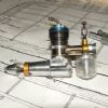
Stirling Engine : Laura
A premilled kit by Bengs
| JasonB | 01/01/2016 07:43:57 |
 25215 forum posts 3105 photos 1 articles | Why not drill & tap the baseplate, drill the bottom of the cylinder support (clamp the two bits together as you drill down the joint) and then just use cap heads from above which will match the way the bearing supports are fitted |
| Brian John | 01/01/2016 08:20:06 |
| 1487 forum posts 582 photos | Jason : I do not think there is enough meat to drill the bottom of the cylinder supports. I am not sure I follow ? |
| Kettrinboy | 01/01/2016 09:39:11 |
| 94 forum posts 49 photos | Whichever way you decide to finally fix the cylinder assembly to the base plate wait until you have the whole thing running and then adjust it until it runs at its fastest until tightening it down as stirlings wont tolerate much if any misalignments that cause friction , just choose a method that gives a little wiggle room to let it all run as freely as possible, the brass angle method sounds pretty good to me , leave say 0.5 mm clearance in the holes for fine adjustments before tightening down.i definitely woulnt go down the silver soldering route as it could distort the base plate then you would have problems. |
| Ian S C | 01/01/2016 10:03:54 |
 7468 forum posts 230 photos | I would drill the base plate, and tap the holes in the bottom of the stand, put the screws in from underneath, use a reasonable size screws, or the whole thing will rock as it runs. One of my flame lickers is mounted that way, and only has three 1/8" Whitworth screws, and it flexes a bit, but as it hasn't broken I'm not fixing it, my usual 3/16"/10 32 UNF would be what I would replace them with, 5 mm would be OK. Ian S C |
| Ajohnw | 01/01/2016 11:24:58 |
| 3631 forum posts 160 photos | I would follow either Jason or Ian's suggestion Brian. Probably Jason's as I would use countersunk headed from underneath which would leave zero scope for adjustment. One thing you should check on your drill - are the drills square to the table? Often they can be adjusted on one plain. Out of square can cause holes to wander about. An automatic centre punch helps or in in critical places a centre drill first - those can be pulled a little with care. A small toolmakers square can be a useful thing to have about. They usually come with 3 blades. On straight, one angled at each end and a narrow one that can be used to measure. The blades are 100mm / 4" long.
John - |
| Brian John | 05/01/2016 06:24:31 |
| 1487 forum posts 582 photos | I have cut two glass cylinders/tubes from the supplied test tubes. I put masking tape around the test tube where it is held in the chuck. I held a diamond file on its edge to cut through the tube while the lathe was set to a low speed. The triangular file would have been better but it is not a diamond file so it would not cut very well. Once I had cut through it then I cleaned up the edge with the flat of the diamond file and then removed it from the lathe to give it a final polish with 1500 grit sandpaper. I would have liked to make a tool holder for a dremel diamond wheel as somebody suggested above but I am still waiting for some square bar stock. For some reason I never ordered any square bar before...only round ! Next step is to make the aluminium piston to fit the glass cylinder. I am not looking forward to this at all because I have to try to round the end of the piston by hand to get a good fit in the end of the cylinder.
Edited By Brian John on 05/01/2016 06:25:23 |
| Martin Connelly | 05/01/2016 10:35:02 |
 2549 forum posts 235 photos | Make a stiff card radius gauge to check against if you are going to manually make the radius. It does not need to be a perfect curve as it going to be in the bottom a test tube that is probably not a perfect hemisphere anyway. It just needs to look good in the tube. Martin |
| Brian John | 05/01/2016 11:09:05 |
| 1487 forum posts 582 photos | I still think it is bad idea making things out of glass and it only complicates the issue of making a piston to fit. I know they chose glass because of it low thermal conductivity but I have seen similar Stirling engines with stainless steel cylinders. If I can get this engine to work with the glass cylinder then I will try to replace it with a stainless steel one at a later stage. Andrew : did you get your Stirling engine to work ? Next problem is the connecting rod for the working piston : I have to drill a 2mm hole through the 3mm steel rod. This is not going to be easy. I would hardly think I can mark the hole with a punch like I would usually do. How would you go about doing this and ensure that the hole is in the centre ? I have a bench drill and a drill press vice. .
Edited By Brian John on 05/01/2016 11:12:15 |
| steamdave | 05/01/2016 12:11:07 |
| 526 forum posts 45 photos | Posted by Brian John on 05/01/2016 11:09:05:
Next problem is the connecting rod for the working piston : I have to drill a 2mm hole through the 3mm steel rod. This is not going to be easy. I would hardly think I can mark the hole with a punch like I would usually do. How would you go about doing this and ensure that the hole is in the centre ? I have a bench drill and a drill press vice. Brian Make a simple (reusable) jig. More pics in Cross Drilling Jig album, but I don't know how to post more pics in this reply. Dave
|
| Andy Holdaway | 05/01/2016 12:39:27 |
 167 forum posts 15 photos | Brian, No, still not working, but in fairness I threw in the towel after a couple of hours. I will give it some more time at the weekend. I did strip it back down, and have reasonable compression on the working cylinder, and all the linkages are free. If I give the flywheel a spin (with everything connected) it will rotate for about seven turns before stopping, so I don't think anything is binding. There are no leaks in the air path that I can tell, and the air from the displacement cylinder is reaching the working cylinder, so I haven't a clue why it wont sustain motion. Time may tell! As for drilling the connecting rod, the end that has to be drilled has to be filed down on both sides to create two flats. Once this was done I centre dotted it and drilled it easily. If it was still round it wouldn't have gone quite so well. Andy |
| Brian John | 05/01/2016 12:44:39 |
| 1487 forum posts 582 photos | Yes, of course : File the flats first ! Andrew : How much gap do you have between the pistons and the cylinders at TDC. I did read somewhere that this gap has to be as small as possible on Stirling engines. I cannot remember if they were referring to the work or displacement piston/cylinders...perhaps both. NOTE : I will make the M3 thread on the end of the connecting rod 12mm long and not 6mm long as per the instructions. I want to install two locknuts there so as to make the length adjustable. All my steam engines have been constructed this way. Edited By Brian John on 05/01/2016 12:45:04 |
| Andy Holdaway | 05/01/2016 12:52:38 |
167 forum posts 15 photos | Brian, that's a good point about the pistons at TDC. The displacement cylinder is virtually touching the end of the glass cylinder (perhaps 0.5mm clearance). I haven't checked the work cylinder, but will have a look tonight. If the gap is too big I can always make a connecting rod to your suggestion. I'll let you know what I find! Andy |
| JasonB | 05/01/2016 13:21:11 |
25215 forum posts 3105 photos 1 articles | Glass makes it easier to get the piston to fit, you can slip the glass over the piston and SEE what it fits like Have you given any thought as to how you might make a deep flat bottomed hole in stainless? |
| Ian S C | 05/01/2016 13:43:22 |
7468 forum posts 230 photos | Brian, don't worry too much about the power piston, just don't get too close too the end of the cylinder, allow a couple of mm. I usually make my con rods from flat material, usually aluminium 1/4" thick. The width is chosen to take in the width of the big end bearing, plus a little, I mark a centre line, then mark the position of one of the bearing holes, then set the distance on a pair of dividers and mark of the other bearing and centre pop that one, it's then a case of drilling the holes. I use a little bronze bush in the little end bearing, and a ball bearing in the big end, except when the crankshaft design won't allow this, in these cases a split bronze bearing is held in place with a cap held in place by bolts. Here's one of each. I do ramble on a bit. Ian S C |
| Brian John | 05/01/2016 13:49:24 |
| 1487 forum posts 582 photos | Jason : with my small boring bar...maybe Or perhaps make the cylinder as best I can with the boring bar and then drop an already machined 2 to 3mm thick disc down the cylinder and Loctite it in position : we now have a flat bottom cylinder. Edited By Brian John on 05/01/2016 13:53:12 |
| pgk pgk | 05/01/2016 14:47:45 |
| 2661 forum posts 294 photos | Posted by Brian John on 05/01/2016 13:49:24:
Jason : with my small boring bar...maybe Or perhaps make the cylinder as best I can with the boring bar and then drop an already machined 2 to 3mm thick disc down the cylinder and Loctite it in position : we now have a flat bottom cylinder. Edited By Brian John on 05/01/2016 13:53:12 Or a tube with an interference fit disc tapped in? Or not worry abut it being flat bottomed.. just drill it and bore to the drill taper and make the piston tip to the same angle with the top side? Od not even bore it, just drill since the displacer is a loose fit. The one I'm slowly building (butchering) uses glass cyinders and pistons. I like the idea of seeing the movement. |
| Brian John | 06/01/2016 07:02:02 |
| 1487 forum posts 582 photos | I made the connecting rod (13) today. I actually made four of them, two of which have been discarded. I decided not to drill the hole out to 2mm on the flat of the rod ; I have left it at 1.8mm. It will not now accept the 2mm rivet as per the instructions when fitting to the piston joint (14) but I will use a 10BA screw and nut with Loctite to hold it together instead. I thought drilling a 2mm hole was really pushing it too close to the edge of the rod. I have put 12mm of M3 thread on the other end so I can fit two lock nuts. This will allow me to make adjustments to the length of the connecting rod.
Edited By Brian John on 06/01/2016 07:02:40 |
| Brian John | 07/01/2016 06:27:09 |
| 1487 forum posts 582 photos | I had a go at making the displacement cylinder today. I am getting there but the process has raised a number of questions. I made the bullet shape by producing a 30 degree taper and then rounding it off by hand using a large file. Jason : you are right. Turning the taper using the top slide wheel is much easier than I thought it would be...no handle required. 1. Why is it the piston made of aluminium ? I hate this stuff and my lathe does not like it either. It gums up my drill bits and my reamers and I find it almost impossible to tap. I have to drill and tap for an M3 grub screw that will hold the piston rod in position but I doubt it will be successful. I have had problems in the past tapping aluminium. If the piston HAS to be aluminium then I may have to make a brass sleeve and tap that and Loctite it in position in the piston. 2. My lathe chuck always gets very hot when working with aluminium. I noticed this a few weeks ago when I was making the aluminium columns (part 30). Why should this be ? Brass does not cause the same problems. 3. The ID of the glass cylinder is 13.2mm. The instructions say to make the piston 12.5mm but this seems like a very sloppy fit. You can see in the photo that I attempted to make one to this size (actually 12.45mm) but then stopped and made another one to 13mm diameter. This seems a much better fit and still plenty of room for free movement ie. it does not touch the sides of the glass tube. Any thoughts on this ?
Edited By Brian John on 07/01/2016 06:28:15 |
| Hopper | 07/01/2016 07:35:05 |
 7881 forum posts 397 photos | Brian there has to be room between the displacer piston and the cylinder ID for the air being displaces from one end to the other to flow unimpeded. Also, there has to be room for the piston to move up and down without touching the cylinder at any point -- sometimes a bit tricky if the alignment of the piston rod and bushing are not quite spot on, or as the bushing wears a bit. Half a millimeter clearance all round is not unusual, so a total of 1mm difference in diamter. |
| Danny M2Z | 07/01/2016 07:56:06 |
 963 forum posts 2 photos | Brian, what type of aluminium alloy are you using? Something like 2024-T3 is nice to machine, the cheesy soft stuff from the usual suspects (B**nings etc) is crapola. * Danny M *
|


.jpg")


Please login to post a reply.
Magazine Locator
Want the latest issue of Model Engineer or Model Engineers' Workshop? Use our magazine locator links to find your nearest stockist!
Sign up to our Newsletter
Sign up to our newsletter and get a free digital issue.
You can unsubscribe at anytime. View our privacy policy at www.mortons.co.uk/privacy
Latest Forum Posts
- *Oct 2023: FORUM MIGRATION TIMELINE*
05/10/2023 07:57:11 - Making ER11 collet chuck
05/10/2023 07:56:24 - What did you do today? 2023
05/10/2023 07:25:01 - Orrery
05/10/2023 06:00:41 - Wera hand-tools
05/10/2023 05:47:07 - New member
05/10/2023 04:40:11 - Problems with external pot on at1 vfd
05/10/2023 00:06:32 - Drain plug
04/10/2023 23:36:17 - digi phase converter for 10 machines.....
04/10/2023 23:13:48 - Winter Storage Of Locomotives
04/10/2023 21:02:11 - More Latest Posts...
- View All Topics
Support Our Partners


Shopping Partners
Subscription Offer

Latest "For Sale" Ads
- Reeves** - Rebuilt Royal Scot by Martin Evans
by John Broughton
£300.00 - BRITANNIA 5" GAUGE James Perrier
by Jon Seabright 1
£2,500.00 - Drill Grinder - for restoration
by Nigel Graham 2
£0.00 - WARCO WM18 MILLING MACHINE
by Alex Chudley
£1,200.00 - MYFORD SUPER 7 LATHE
by Alex Chudley
£2,000.00 - More "For Sale" Ads...
Latest "Wanted" Ads
- D1-3 backplate
by Michael Horley
Price Not Specified - fixed steady for a Colchester bantam mark1 800
by George Jervis
Price Not Specified - lbsc pansy
by JACK SIDEBOTHAM
Price Not Specified - Pratt Burnerd multifit chuck key.
by Tim Riome
Price Not Specified - BANDSAW BLADE WELDER
by HUGH
Price Not Specified - More "Wanted" Ads...
Get In Touch!
Do you want to contact the Model Engineer and Model Engineers' Workshop team?
You can contact us by phone, mail or email about the magazines including becoming a contributor, submitting reader's letters or making queries about articles. You can also get in touch about this website, advertising or other general issues.
Click THIS LINK for full contact details.
For subscription issues please see THIS LINK.
Digital Back Issues


Donate

 Register
 Log-in
Model Engineer Magazine
- Percival Marshall
- M.E. History
- LittleLEC
- M.E. Clock

ME Workshop
- An Adcock
- & Shipley
- Horizontal
- Mill

Subscribe Now
- Great savings
- Delivered to your door

Pre-order your copy!
- Delivered to your doorstep!
- Free UK delivery!
All Forum Topics > Stationary engines > Stirling Engine : Laura