Member postings for Andrew Johnston
Here is a list of all the postings Andrew Johnston has made in our forums. Click on a thread name to jump to the thread.
| Thread: Vertex Auto Tapping Head |
| 19/06/2011 23:24:40 |
I don't have any experience of the Vertex tapping head, but I do have two of other makes. The small one, up to 1/4" is a Tapmatic, bought new, and the bigger one, up to 1/2", is an Edalmatic, bought on Ebay. I've only ever used them on the Bridgeport mill, but then again I only use my pillar drill a couple of times a year for 'bodge' jobs. As John says, they're magic for large numbers of holes, and very quick. I bought the Tapmatic when faced with 800+ 8BA holes to tap. Running at 800rpm it was much quicker to tap the hole than drill it. I've only every used machine taps with my tapping heads, spiral point and spiral flute. I guess there's no reason you couldn't use hand taps, but it'd be awfully slow, rather negating the use of the tapping head. And there's always the problem of picking up the thread in an existing tapped hole without cross threading. Of course on the other hand there's nothing to stop you using machine taps by hand. I sometines use a spiral flute tap by hand if I really need the thread to reach the bottom of a blind hole. I also have, but haven't yet tried on the tapping head, a roll form tap. If you have the need to tap a large number of holes I'm sure you won't regret getting a reversing tapping head. Regards, Andrew |
| Thread: A Challenge - How Would You Machine This Part? |
| 19/06/2011 19:20:30 |
Phil: You won't get any rude comments from me; if you don't want to use CNC that's fine by me. Steve: The comment on over-engineering was a gentle nudge at an earlier respondent, who threw his teddy out of the pram, turned the pram over, and then stomped off. I didn't want to overfill the post with pictures, so it might have looked a bit misleading. The gear teeth were roughed out with a 4mm ball nose cutter, as shown. That was followed by a quick pass with a 3mm ball nose cutter to clean out the small end, and then a final pass with fine stepover with a 2mm ball nose cutter. The final gears as shown are straight off the machine tool, apart from a little deburring of the tooth ends where I machined the tapers on a (manual) lathe. The comment on the steering gear is a project in hand. The drawings I have are completely inadequate. They only say that the worm is two start, 0.5" pitch and give the OD and a lead angle. The worm wheel simply says 22 teeth and gives an OD. The supplier I get my castings from uses a helical spur gear for the worm wheel, which is of course perfectly adequate, if not prototypical. But I got to thinking (dangerous I know), could I make a proper hob and consequently make a proper worm wheel. Like everybody else I've made worm wheels using a tap as a hob, but I've never made one using a 'proper' hob. Once I've checked my maths and tidied up the 3D models I'll start another thread. Regards, Andrew |
| Thread: Arc Euro Trade High Speed Spindle Motors |
| 18/06/2011 18:04:20 |
I rang John yesterday, and listened to the motor and inverter running. We had a perfectly audible conversation with John standing right next to the motor. That's very encouraging and I will be looking at the purchase of one of these motors and inverters in a lot more detail. Thanks John!  While the recent machining of bevel gears has highlighted the lack of spindle speed on my mill (it is limited to just over 5000rpm) this is not the first time the issue has arisen. Last year, for work-related prototypes, I needed to do some engraving. After several broken cutters, poor finishes and general frustration I eventually got the job done with a 4 flute 60° chamfering cutter. However, the over-riding problem was lack of spindle speed. At one time I had an old Taylor Hobson manual engraver, this run at about 18000rpm I believe, and produced excellent work. Just slowing the feedrates down proportionally doesn't seem to be as effective. Regards, Andrew |
| Thread: A Challenge - How Would You Machine This Part? |
| 18/06/2011 17:55:45 |
So, for my 400th post on this forum, I am proud to present another load of grossly over-engineered twaddle.  After a bit of a delay, partly due to work and partly due to toolpath issues, I've finally finished machining the prototype crown bevel gear. In one sense this is more complex than the pinion, in that the radius at the bottom of the tooth requires a 2mm cutter, but clearly it wouldn't be sensible to use that for roughing out. In the end I roughed out with a 4mm cutter, did a quick clean-up pass with a 3mm cutter and finished with a 2mm cutter. On the other hand the crown wheel is simpler than the pinion, in that it does not require the use of the 4th axis. The crown wheel blank: After roughing out: 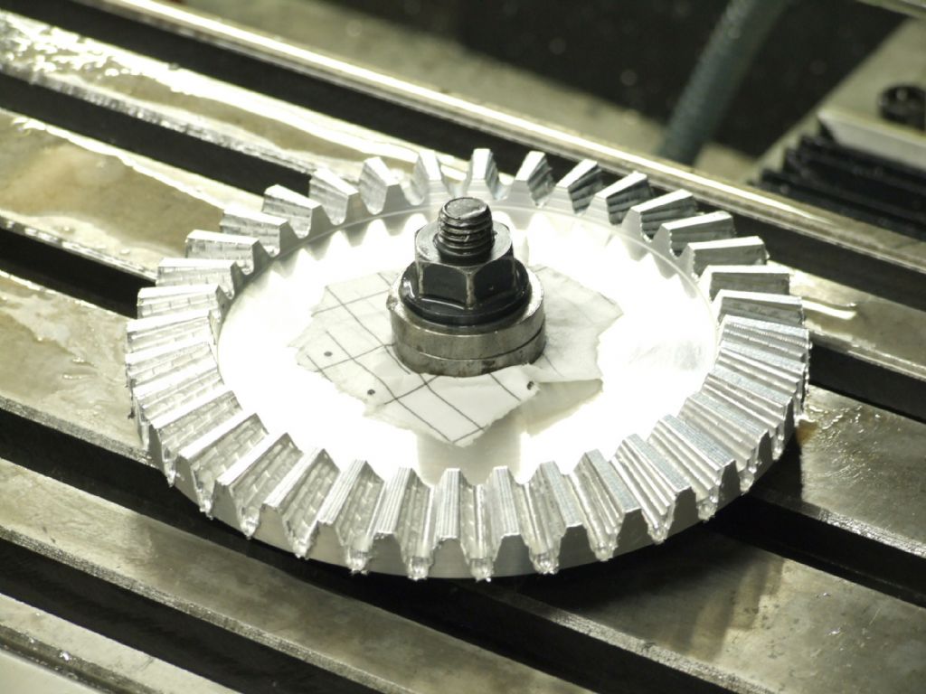 And the finished gears: 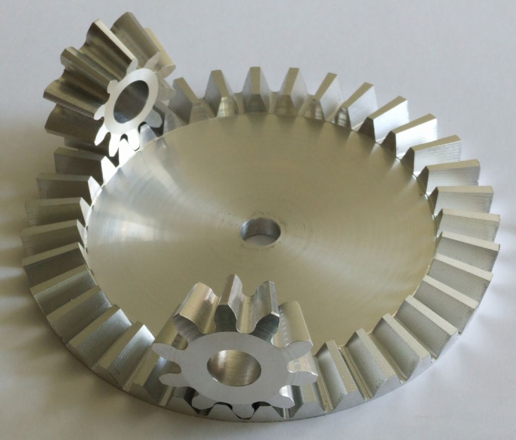 The gears mesh together extremely well; better than one might have thought looking at the finish. All I need to do now is make the real gears in cast iron. Regards, Andrew PS: If you think this is over-engineered, you ain't seen nuffink yet, wait till I get onto the steering gear.  |
| Thread: Arc Euro Trade High Speed Spindle Motors |
| 16/06/2011 19:47:00 |
Thanks for the replies. In due course I'll give Arc a call; I was rather put off by the notices on their website saying they couldn't help with advice on the high speed spindles. I'm perfectly capable of deciding what I want to use the spindle for, and of dealing with all the wiring. But these are not cheap items, and advice on the suitability of the unit from the noise viewpoint would seem to be a reasonable thing for them to answer. Martin: Thanks, that's very helpful, and rather encouraging, anything more than that and I suspect it will be a non-starter in my quiet rural area. So far my only experience of high speed motors is a secondhand 3kW router motor on a test rig that I designed and made which we pushed to 24000rpm to drive a F1 car alternator, as part of a work project. Talk about noisy! Best Regards, Andrew |
| Thread: never seen anything like it |
| 15/06/2011 19:18:06 |
Since there are no pictures, technically you're the only person who has seen it!  Regards, Andrew |
| Thread: milling vices |
| 14/06/2011 22:46:58 |
I was under the, possibly mistaken, impression that toolmakers vices are intended for precision grinding and maybe a little light milling. They are not intended to be general purpose machine vices. That may explain why the base is a box section. Regards, Andrew On edit: Graeme has mentioned the name, so I can now say that my main machine vice is a Kurt D688. However, it is far too big for a Dore-Westbury, and they are not cheap! Kurt do a slightly smaller version, but perversely it is more expensive than the bigger vices. All to do with sales volumes I expect. Edited By Andrew Johnston on 14/06/2011 22:50:48 |
| Thread: Arc Euro Trade High Speed Spindle Motors |
| 14/06/2011 17:44:13 |
So, I'm bored waiting for a 2mm cutter to do the business at 5000rpm and 150mm/min feedrate. It's a carbide cutter, in aluminium, so I should be able to run it much faster. I note that Arc Euro Trade do a series of high speed spindle motors and associated VFDs. I'd be interested in the smallest setup, about 0.5hp. The question is, does anyone have practical experience of these particular motors and VFDs? At this stage there are three things I'm interested in. One and two, the radial and axial runout; does it meet the 0.005mm quoted? And third, how noisy are the motors. A dB(A) number would be ideal! I live in a quiet rural village, and this motor may be running for several hours, so the neighbours won't thank me if it is noisy. Regards, Andrew |
| Thread: milling vices |
| 13/06/2011 22:20:41 |
I wondered that too, if the supposedly fixed jaw is moving 20thou then I suspect the vice needs recycling. The OP mentions that the vice is fabricated; may be that indicates it is home made rather than bought? Just out of curiosity I thought I'd measure my main machine vice, as the fixed jaw is not integral with the body. I tightened the vice against two parallels as tight as I could, using the manufacturers handle. I could just detect some movement of the fixed jaw on a 0.01mm DTI, may be a needles width, so less than a tenth of a thou in real money. The movable jaw lifted by 1 division, 0.01mm, or 4 tenths of a thou in real money. Waaaaay better than than the vice it replaced where the movable jaw lifted between 10 and 20 thou depending upon how tight the gibs were. Regards, Andrew |
| Thread: Anyone here ever used a magnetic chuck? |
| 09/06/2011 18:55:48 |
Yes, but................. I use a permanent mag chuck on my surface grinder. There are circular mag chucks available for cylindrical grinders, but personally I wouldn't want to use one on a lathe. The holding forces of the mag chuck are not that high when compared to the forces generated by the cutting process. Secondly the holding forces are disproportionally affected by small air gaps, so unless the item to be machined is already pretty flat it'll probably part company with the chuck before machining commences. No doubt some-one does/has machined on the lathe with a mag chuck, but I wouldn't want to. Regards, Andrew |
| Thread: The ongoing saga of John's floor |
| 09/06/2011 18:48:52 |
Well, you could use a helical broach, but I suspect it's not the sort of tool you have lying about on the off chance. Could use EDM, but again not the sort of machine most people have. It would be possible to do it on the lathe, but it would be a funny looking tool to get the right clearances. More of a shaping action. So it could be done on a shaper or slotter with the right feed mechanism. It could probably be done on a manual mill if the nut was split and done in two halves. However, the nut looks like plastic or anodised aluminium? If plastic then the thread could be made by a heated screw, or a simple home made broach. But, since this was presumably a repair job, and was done in an afternoon, I prefer the 'slap some goo around the screw and make a moulding' approach. Could use resin or one of 'liquid metals' for better strength. Whatever way, it's out of my league. Regards, Andrew |
| Thread: A plastic valve |
| 09/06/2011 18:40:35 |
Plug the main bore before drilling. Drill through body and into plug. Remove plug; result no burrs. Regards, Andrew |
| Thread: The ongoing saga of John's floor |
| 09/06/2011 08:36:26 |
Ok John, so I can think of ways to machine an eight start screw, but how on earth do you make the nut? Andrew |
| Thread: A Challenge - How Would You Machine This Part? |
| 07/06/2011 08:02:00 |
That's why I said handraulic, not hydraulic, precisely because it is a hand ratchet. Regards, Andrew |
| 06/06/2011 22:40:54 |
There definitely appears to have been some confusion here. It was never my intention to make castings from patterns; indeed I hadn't even thought of castings until it was mentioned by Jason.It's an interesting thought though! Jason is also quite correct in stating that I am machining in aluminium simply to check the G-code and learn about stepover values versus surface finish. At some point even I stop thinking and do some experiments. Aluminium is cheap and readily available (here I apologise to Richard P) whereas I will have to order cast iron specially, and the real crown wheels are actually castings with other features attached. It was never my intention to suggest that all this effort was needed to make gears for a traction engine differential. That is why the purpose of the gears wasn't mentioned in the original post. In fact the post was originally intended to be a gentle nudge to the 'no CNC' protagonists. May be it is fortunate that it has morphed into something else. My horizontal mill was a snap decision buy, on offer from a model engineering tool dealer (not normally noted for cheap prices) at a knock down price. I assume they'd got a job lot from a college, and, since it is a larger machine than might normally be found in a home workshop, they just wanted to move them on. It cost more to have it delivered than the mill itself cost. So far I haven't even managed to get the motor to change note, let alone struggle. I've cut all the pinion gears for the traction engines on it, 6DP in EN8 and 5DP in cast iron, in one pass, with not even a cough from the motor. Interesting pictures posted by Jason. The bevel pinions must have been CNC'd, difficult to see how else it could have been done given that the teeth are effectively pockets. It looks like the stepover used was radial rather axial. I chose axial, as then at least the machining marks are parallel to the line of contact. Wow, it must have taken ages to machine the holes for pinions by handraulic means. I wonder how the pockets for the pinions were done, doesn't look machined, but too clean for flame cut, laser or water jet maybe? Ah, now JohnS has opened another whole can of worms. I was only thinking earlier this evening, while weeding one of the fruit bush areas in the garden, about the steering worm and wheel for the traction engine. I have seen a worm, machined by CNC, at my supplier, and frankly it looked a little rough, I could do better! But I may well end up machining the worm (two start) by manual means. But what about the worm wheel. My supplier, in common with others I expect, simply uses a helical spur gear. Perfectly adequate for the job of course. But, being obtuse, I wondered if I could machine a proper worm wheel. I have the kit to do it, if I had the necessary hob. The question then becomes could I machine a suitable hob, with relief, on the CNC mill? Watch this space. Regards, Andrew |
| 05/06/2011 22:58:15 |
JohnS, Presumably the dividing head still needs to be driven by a stepper motor? I do have a universal dividing head, but it is not motorised. Regards, Andrew |
| 05/06/2011 22:51:51 |
And so to the delicate task of replying to JasonB and mgj. I hope you don't mind me making it a combined reply. I am fully aware that the differential gears in full size are 'as cast' and that they are slow moving and lightly loaded. I suspect that at the time it would have been pretty difficult, and very expensive, to get bevel gears machined. I believe that the Gleason bevel planer was invented in 1874, but I assume it took quite a while to cross the Atlantic, and become established. I hadn't thought of having the gears cast, although it would have been an interesting exercise. Of course in order to make the patterns I would have had to go through the same design process, which is what took most of the time! mjg - Well why not?! I could have made the bevels by the parallel depth method and as mentioned I did do all the calculations for a range of pinion and crown wheel sizes to get ODs that were a close match to the existing drawings. However it would have still involved quite a lot of work in re-designing other parts and ensuring that they still fitted together. I must be slow, because I'm sure I couldn't do the necessary calculations in 5 minutes, and it would take me longer that three nights to do the machining. As an aside I am actually building two engines, and this design has three pinions in the differential, not two. So that's six pinions and four crown wheels. There are some things in mjg's post I don't follow. What are the advantages of parallel tooth bevels? Errr, I thought that was exactly what my method did do, it makes the gears from a standard length of bar? I don't follow the reasoning for using a vertical mill, surely a horizontal mill would be easier? Lastly I don't understand why more than one arbor would be needed. I only used one arbor to make the pinions, took me about half an hour to make. It doubles up for use in the lathe to make the initial blanks, on the mill to cut the teeth, and back on the lathe to finish the front and back chamfers. I have a vertical mill, a horizontal mill, a CNC mill and a universal dividing head, so I could have chosen any of the methods mentioned. I've even got a hacksaw and round file, but not the patience! After a lot of thinking and designing, and false starts, I did it the way I did because it was a challenge, I'm interested in the design and manufacturing process. I feel that I now know a lot more about the way bevel gears are designed, the mathematics of involute curves and the tooth shapes and how to calculate them, and the means of making the gears, including the approximate methods. At the end of the day, each to his own, and good luck to them. Regards, Andrew PS: Did you know that the use of the involute curve of the circle was first suggested for use in gears by Euler? |
| 05/06/2011 21:14:19 |
Hi JohnS, Thanks for the explanations of Gearotic. Now that I look at it with fresh eyes I see that the cutting information is available on the output page. I also now understand why the 5 axis is needed. Tormach do a 5 axis add-on, driven rotary table with a manual tilt, but it is pretty expensive and would be expensive to ship, plus VAT, plus import duty plus....well I expect you get the picture. I could machine a fixed block to tilt my rotary table, but I think I'll stick with my existing method for the moment. However, I am interested in Gearotic. I did look at it more than a year ago but decided against buying it. But now, after consulting the keeper of the purse strings, I think I will make a purchase. If nothing else I will be interested to look at the generated G-code and plot out the consequent toolpath. At some point I will need to machine a helical gear for the steering on the traction engines and Gearotic will give me another option, ie, CNC versus manual machining. Even if I decide to machine the helical gears manually Gearotic may help to generate a 3D model. Thanks again. Regards, Andrew |
| 05/06/2011 20:45:12 |
Hi Nick, Yes, I rather gathered that the drawings were intended to be tongue-in-cheek, but nonetheless amusing. They certainly lightened my day; excellent choice of accompanying beverages by the way!I shall be interested to see how I get on cutting the cast iron. I'm nowhere near the speeds recommended by the cutter manufacturer for aluminium, in fact I'm running at the bottom end of the speeds they recommend for cast iron. So as a first pass I'll stick with the same speeds and feeds and see how I get on. Regards, Andrew |
| Thread: Prams and teddies again |
| 05/06/2011 11:40:45 |
Paaah, it's much more fun throwing teddies! Mind you this is all WI stuff compared to the tantrums, hissy fits and teddy throwing that I've seen on the flying field, particularly in competitions. If nothing else the 'controversial' threads seem to attract a lot more posts than the more technical ones; that might say something? Regards, Andrew |
Want the latest issue of Model Engineer or Model Engineers' Workshop? Use our magazine locator links to find your nearest stockist!
Sign up to our newsletter and get a free digital issue.
You can unsubscribe at anytime. View our privacy policy at www.mortons.co.uk/privacy
- hemingway ball turner
04/07/2025 14:40:26 - *Oct 2023: FORUM MIGRATION TIMELINE*
05/10/2023 07:57:11 - Making ER11 collet chuck
05/10/2023 07:56:24 - What did you do today? 2023
05/10/2023 07:25:01 - Orrery
05/10/2023 06:00:41 - Wera hand-tools
05/10/2023 05:47:07 - New member
05/10/2023 04:40:11 - Problems with external pot on at1 vfd
05/10/2023 00:06:32 - Drain plug
04/10/2023 23:36:17 - digi phase converter for 10 machines.....
04/10/2023 23:13:48 - More Latest Posts...
- View All Topics


- Reeves** - Rebuilt Royal Scot by Martin Evans
by John Broughton
£300.00 - BRITANNIA 5" GAUGE James Perrier
by Jon Seabright 1
£2,500.00 - Drill Grinder - for restoration
by Nigel Graham 2
£0.00 - WARCO WM18 MILLING MACHINE
by Alex Chudley
£1,200.00 - MYFORD SUPER 7 LATHE
by Alex Chudley
£2,000.00 - More "For Sale" Ads...
- D1-3 backplate
by Michael Horley
Price Not Specified - fixed steady for a Colchester bantam mark1 800
by George Jervis
Price Not Specified - lbsc pansy
by JACK SIDEBOTHAM
Price Not Specified - Pratt Burnerd multifit chuck key.
by Tim Riome
Price Not Specified - BANDSAW BLADE WELDER
by HUGH
Price Not Specified - More "Wanted" Ads...
Do you want to contact the Model Engineer and Model Engineers' Workshop team?
You can contact us by phone, mail or email about the magazines including becoming a contributor, submitting reader's letters or making queries about articles. You can also get in touch about this website, advertising or other general issues.
Click THIS LINK for full contact details.
For subscription issues please see THIS LINK.


 Register
 Log-in
Model Engineer Magazine
- Percival Marshall
- M.E. History
- LittleLEC
- M.E. Clock

ME Workshop
- An Adcock
- & Shipley
- Horizontal
- Mill

Subscribe Now
- Great savings
- Delivered to your door

Pre-order your copy!
- Delivered to your doorstep!
- Free UK delivery!