Member postings for Andrew Johnston
Here is a list of all the postings Andrew Johnston has made in our forums. Click on a thread name to jump to the thread.
| Thread: Bridgeport Milling machine help |
| 18/08/2011 11:12:48 |
I worried that I might have made a boo-boo on the pot value, so I've just been out to measure it. Definitely 50000 ohms not 500. And it only has two wires connected. The control unit was made by Erskine Laboratories in Scarborough. My Bridgeport is an Adcock & Shipley clone, but I'm surprised they used a UK company for the controller. One would have assumed that the parent company would have just supplied their existing, US made, controllers.
The box has a cover over it, but I can just see one of the those old-fashioned Mullard multi-coloured capacitors; haven't seen those since the 1970s! Mind you, my power feed works at the moment, so I'm not going to poke any deeper, as the wiring looks a little 'delicate'.
Addendum: Much to my surprise Erskine is still doing power electronics in Scarborough, albeit now part of much larger group.
Regards,
Andrew Edited By David Clark 1 on 18/08/2011 11:18:40 |
| 17/08/2011 13:55:46 |
Hmmmm, just checked on my Bridgeport, where the pot has been changed at sometime in the past. It's definitely not a genuine Bridgeport pot, as it is far too big to fit in the correct position. It has been bodged into a diecast box which is bolted onto the front of the normal panel. The pot is a Colvern wirewound, 50000 ohms, doesn't say anything about taper law, so I'd guess linear. Regards, Andrew PS: Only two wires are connected, so technically the pot is being used as a rheostat Edited By Andrew Johnston on 17/08/2011 13:57:50 |
| Thread: What is the purpose of centre drill and how does it work? |
| 14/08/2011 13:35:50 |
The primary use for a centre drill is to provide a 60° hole for a tailstock centre as a support during turning. The little drill bit on the end gives clearance, and provides an oil reservoir, for the point of the centre. For drilling, especially for holes where placement accuracy is important, the recommendation was to use a centre drill first and then follow up with conventional drills. You are correct in assuming that because the centre drill is short 'n' fat it is less likely to wander. Personally I think that the above advice is a little outdated now. On a flat machined surface I find that four facet ground drills start accurately without needing a pilot hole. If the surface is rough then I start with a carbide spotting drill. These are essentially stub drills, so are stiffer and less likely to wander. Also carbide is about three times stiffer than HSS, which also helps. In my experience you've only got to look at the smaller centre drills and woof, the centre bit breaks. So I try not to use them, except when I need a centre support hole in turning. There's always an exception to the rule; bizarrely I did use a centre drill as a drill recently, as I needed a countersunk hole that was 60° for some odd screws. Regards, Andrew Edit: Blast, typed too slowly! Sorry for the duplication. Edited By Andrew Johnston on 14/08/2011 13:36:45 |
| Thread: Tang type Morse Taper cutter |
| 14/08/2011 13:24:15 |
I had to look it up, but you're right, B&S tapers are shallower, albeit not by much. Morse tapers are about 0.6" per foot, while B&S tapers are about 0.5" per foot. As far as I'm aware B&S tapers are pretty much obsolete now, presumably being largely limited to Brown & Sharpe machine tools. Regards, Andrew |
| Thread: Whittle V8 - Crankshaft |
| 14/08/2011 11:06:55 |
Steve: Looks pretty damn fine to me! Non-functional errors, pah, as long as it does the job no problem. Nobody will ever notice anyway. Regards, Andrew |
| Thread: Introduction to CNC |
| 14/08/2011 09:50:40 |
Raymond; thanks for the link. Took me a while to find a proper spec on the website amongst all the PR bull about IGBTs and DSP. They are certainly some serious bits of kit, but I wouldn't even think about asking for price, and to cap it all batteries are extra! Steve; funny you should mention converting a three phase VFD. The last power converter I designed was three phase in, 600VDC out, with a rating of 50kW. It was bi-directional so putting 600VDC in gave you three phase out. Perhaps I should see if I can sneak one out of the building. I've also designed a number of lead acid battery management systems for experimental electric vehicles, and I whole-hearted agree that you need to monitor each individual battery and include means for balancing so that all cells are at pretty much the same SOC. Otherwise it all gets out of hand pretty quickly and you end up with badgered batteries. Regards, Andrew |
| Thread: Tang type Morse Taper cutter |
| 14/08/2011 09:40:54 |
Personally, I'd never use a milling cutter relying just on the Morse taper to hold it in place. However, my newest copy of Machinery's Handbook shows both T-slot cutters and endmills with Brown & Sharpe tapers and tangs. The B&S taper is similar to Morse tapers. Not a word about how they are used though. The mystery deepens. Regards, Andrew |
| Thread: Introduction to CNC |
| 13/08/2011 15:12:19 |
I do my CAD/CAM on a computer in the office. Only the computer in the workshop that was driving the CNC mill lost the program. Fortunately I still had a copy on the office computer, and on the pen drive I use to transfer between the two.   Regards, Andrew |
| Thread: Myford online auction |
| 13/08/2011 11:20:36 |
I'd really like the Butler planer, but where on earth would I put it.  I've always been fascinated with planers since I saw one in action at W H Allens in Bedford in the early 1970s. Guess I'll just have to wait until I win the lottery and can then buy a big industrial building and fill it full of machine tools. I've always been fascinated with planers since I saw one in action at W H Allens in Bedford in the early 1970s. Guess I'll just have to wait until I win the lottery and can then buy a big industrial building and fill it full of machine tools.Regards, Andrew |
| Thread: Introduction to CNC |
| 13/08/2011 11:14:20 |
Hi David, Thanks for the advice, but unfortunately as the computer went off as well, so the mill completely lost its marbles and also lost the program, so I have no idea where it got to. It's now running again, as I type  , on a new blank. I'm going to make a new blank to replace the one that was partly machined. The roughing cut is programmed to leave 0.2±0.1mm of stock. I don't think I can realign in the A axis to that accuracy as there is nothing to reference against. It'll only take me a few minutes to make another blank, but it is £2 down the drain in material. , on a new blank. I'm going to make a new blank to replace the one that was partly machined. The roughing cut is programmed to leave 0.2±0.1mm of stock. I don't think I can realign in the A axis to that accuracy as there is nothing to reference against. It'll only take me a few minutes to make another blank, but it is £2 down the drain in material.  Steve: I haven't seen a three phase UPS either. As it happens the mill runs on single phase. Eh, what didn't I intimate two phases above? The mill was designed in the US, so the main drives, controls and VFD are intended to run from a 220V supply, ie, 110-0-110. There is a separate, isolated, supply input, normally 110V, to run the computer and with a separate switchable output for things like coolant pumps. The isolated supply is also rated for 220V, so that's what I use for the computer and coolant pump. I was a bit concerned about running the two supplies from different phases, but they have proved to be truly isolated, so everything is fine. I don't think I could afford a UPS(s) with appropriate power ratings. Plus, my experience of UPSs for computers is that they don't work. Several places I have worked have had UPSs fail to do the job when the power goes. The place I'm working at the moment had a big storm a few weeks ago and the power went off for about 8 hours. Not only did the UPS fail to protect the server, it committed hari-kari. There is now a pile of very swollen lead acid batteries on the floor awaiting recycling! Regards, Andrew |
| 12/08/2011 23:36:51 |
The power here was only off for an instant, enough to badger the CNC mill and the clock on the cooker, but not the clock on the microwave. I suspect all three phases went, as the CNC mill and the computer that runs it are on different phases and they both went off, and I think the house is on the other phase. The time before when the power went off it was out for an hour, came back for 15 minutes and was then out for two hours. We have overhead and underground cables in my steet. I get my feed from the underground cable, but I'm pretty sure the ultimate feeds are overhead on telegraph poles. I live in the country, but I'm hardly in the sticks! At least I don't think it's damaged anything, just that I've lost the zero references for the part I was machining. The XYZ references I can get back, but the 4th axis (A) may be a bit more difficult. I'll give it a go tomorrow morning, otherwise it's bin it and start afresh with a new cast iron blank. Regards, Andrew |
| 12/08/2011 22:42:54 |
Interesting, but does it cover what to do when you're 40 minutes into a 3 hour CNC program and the b@*&dy power disappears for a few seconds and everything shuts down, like wot happened this evening? That's the third power cut we've had here in the last two weeks, mumble, mumble, mumble. Every time it rains the power seems to go off. And to add insult to injury E.on have just announced stonking price hikes.In the end I did what any seasoned machinist would do; I went to the fridge and grabbed a beer. Regards, Andrew Hmmm, I wonder if this off-topic post will get me ex-communicated? Edited By Andrew Johnston on 12/08/2011 22:43:18 |
| Thread: Curved flywheel spokes |
| 12/08/2011 14:25:39 |
It's the latter. When hot the metal is weak, so if there is differential cooling, the spokes usually cool first, the spokes may crack at the hub as the hub shrinks. The technical term is 'hot tears'. It can be avoided by correct mould design. Regards, Andrew |
| Thread: MEW 180 |
| 10/08/2011 23:11:30 |
Posted by Alan Jackson on 10/08/2011 22:22:19: Figure 9 on page 40 of MEW180 shows a right angled slit into the bore to clamp the shaft. This is a good example of computer design which is untested. How would you propose a potential builder would cut this slit? Wire EDM |
| Thread: Accuracy in Machining Large Gears |
| 07/08/2011 23:02:08 |
Thanks one and all for the advice. The engines as designed don't have real or dummy springs; just a rear axle that runs in a cast axle tube, that bolts to the hornplates. Being contrary I haven't made the hornplates yet. I intend to made a test bar to measure the centre to centre distances for the gear sets and then adjust the holes in the hornplates accordingly, should they not be to the calculated numbers. I had considered using the dividing head in vertical mode, but the gear would then be the best part of 12" up in the air. That would need some pretty substantial supports to counteract the horizontal cutting forces. With the rotary table the gear will only be about 3" above the milling table, and the rotary table itself will help resist the forces. JohnS: Thanks, I have seen those pictures on my trawl through the web on this subject, but I didn't know you were involved. I should have known better! Michael: That's a succinct summary of the issue, and you're right I don't need to worry! I just need to get on and cut the gears now. Regards, Andrew |
| Thread: mini mills - which is the best? |
| 07/08/2011 22:40:11 |
I can get within a hundredth of a mil What's a hundreth of a mil? It's US speak for a thou; but I doubt you're machining to 10 millionths of an inch. Regards, Andrew |
| Thread: Accuracy in Machining Large Gears |
| 07/08/2011 12:31:00 |
At some point in the near future I'm going to have to face up to cutting the final drive gears for my 4" scale traction engines. Details are; 5DP 20°PA, 72 teeth, OD 14.8". This is just a bit too big to go under the cutter on my horizontal mill. Having considered various alternatives I think that the best solution is to use a rotary table in horizontal mode (on the horizontal mill) and use the knee to apply the cut. The question I have concerns the accuracy of the final gear. My dividing head manual quotes a maximum cyclic inaccuracy of 1°30', and I'd be surprised if the rotary table was any better. Taken on a 14.8" diameter circle this angle equates to a bit over 3 thou. In other words the tooth thickness could vary by 3 thou from tooth to tooth. I can think of two ways round this. One, just cut deeper than theoretical and accept the backlash. For 20°PA the formula seems to be to cut deeper by 0.73 times the required backlash. Two, use a plate with a 72 holes placed on a large diameter, say 12", and use these to index the gear. I think I'm probably going to go with option one, as it is simpler, and I don't need 'precision' gears here. What are other peoples' experiences? By the way, I know that the original, full size, gears would most likely have been 'as cast' and that the tooth engagement varies according to the rear axle springing. So I don't need any smartypants comments about OTT over-engineered twaddle.  Regards, Andrew |
| Thread: What happened to the conclusion of CNC 4th Axis? |
| 04/08/2011 13:06:53 |
I don't think that the scientific review process is applicable to 'hobby' magazines such as MEW. The purpose of peer review is to assess the validity of the work such as, is it original, are the conclusions reasonable from the work and/or data presented, does it add to the body of knowledge, is previous work correctly cited etc? It is not intended to correct basic errors. That is left to the author, who will receive proofs from the printers prior to publication to correct layout and composition errors. It can be a lengthy process, usually a year or more, from initial submission to publication and usually involving re-writes.This is an expensive process which is why subscriptions to scientific journals often run to hundreds, or thousands, of pounds per year. I suspect that if the same criteria were applied to MEW there would be very few articles to publish. After all there's very little in MEW that is genuinely new, in the scientific sense. Regards, Andrew |
| Thread: A New Dividing Plate for my Dividing Head |
| 01/08/2011 20:22:10 |
Just to round off part of the thread I have now started cutting the gears using my new division plate. Two sets, each with one gear with 63 teeth and one with 69 teeth. Here's the division plate in position: 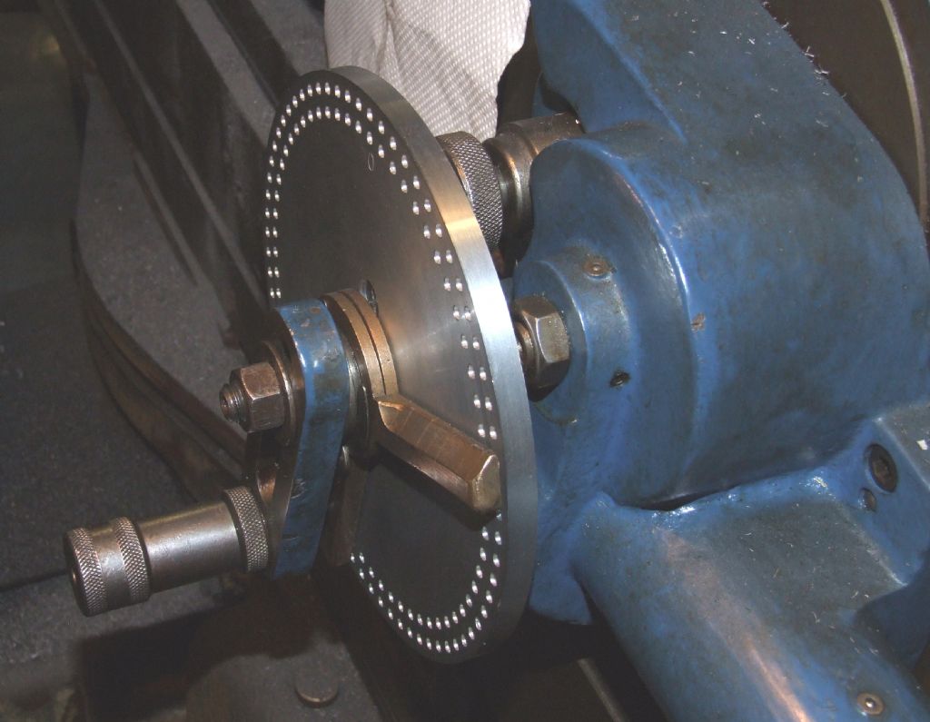 The larger of the two gears being cut: 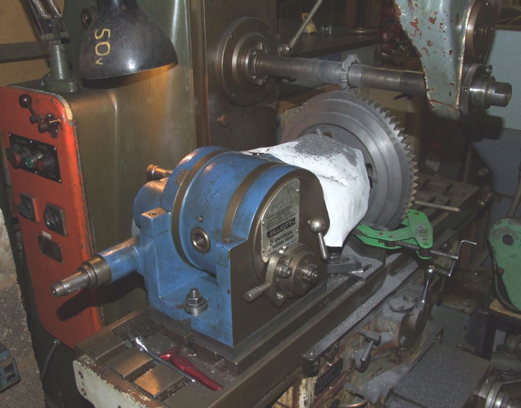 And finally the two gears, together with the part machined differential centre: 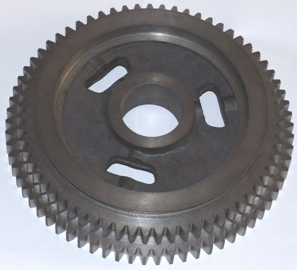 For reference the larger gear is a shade under 12" in diameter. The more observant will note the green clamp in the picture of the gear cutting in progress. This is to stop the gear rotating during cutting. First time round I optimistically assumed that the dividing head spindle lock and tailstock would be sufficient, given that the cutting forces, in theory, are along the x axis. Sadly my optimism was misplaced, and on the 60th or so tooth the gear slipped by about 20 thou on the periphery. I've been round and recut the gear, and I'm sure that in practice it would work, but I'm not happy with it, so I've ordered a new casting. An expensive lesson learnt. Regards, Andrew |
| Thread: Elliot 10M Shaper. |
| 28/07/2011 16:32:59 |
Is it a disease to keep wanting to buy machinery. ??. Yes, it's called OIS, old iron syndrome. Regards, Andrew |
Magazine Locator
Want the latest issue of Model Engineer or Model Engineers' Workshop? Use our magazine locator links to find your nearest stockist!
Sign up to our Newsletter
Sign up to our newsletter and get a free digital issue.
You can unsubscribe at anytime. View our privacy policy at www.mortons.co.uk/privacy
Latest Forum Posts
- *Oct 2023: FORUM MIGRATION TIMELINE*
05/10/2023 07:57:11 - Making ER11 collet chuck
05/10/2023 07:56:24 - What did you do today? 2023
05/10/2023 07:25:01 - Orrery
05/10/2023 06:00:41 - Wera hand-tools
05/10/2023 05:47:07 - New member
05/10/2023 04:40:11 - Problems with external pot on at1 vfd
05/10/2023 00:06:32 - Drain plug
04/10/2023 23:36:17 - digi phase converter for 10 machines.....
04/10/2023 23:13:48 - Winter Storage Of Locomotives
04/10/2023 21:02:11 - More Latest Posts...
- View All Topics
Support Our Partners


Shopping Partners
Subscription Offer

Latest "For Sale" Ads
- Reeves** - Rebuilt Royal Scot by Martin Evans
by John Broughton
£300.00 - BRITANNIA 5" GAUGE James Perrier
by Jon Seabright 1
£2,500.00 - Drill Grinder - for restoration
by Nigel Graham 2
£0.00 - WARCO WM18 MILLING MACHINE
by Alex Chudley
£1,200.00 - MYFORD SUPER 7 LATHE
by Alex Chudley
£2,000.00 - More "For Sale" Ads...
Latest "Wanted" Ads
- D1-3 backplate
by Michael Horley
Price Not Specified - fixed steady for a Colchester bantam mark1 800
by George Jervis
Price Not Specified - lbsc pansy
by JACK SIDEBOTHAM
Price Not Specified - Pratt Burnerd multifit chuck key.
by Tim Riome
Price Not Specified - BANDSAW BLADE WELDER
by HUGH
Price Not Specified - More "Wanted" Ads...
Get In Touch!
Do you want to contact the Model Engineer and Model Engineers' Workshop team?
You can contact us by phone, mail or email about the magazines including becoming a contributor, submitting reader's letters or making queries about articles. You can also get in touch about this website, advertising or other general issues.
Click THIS LINK for full contact details.
For subscription issues please see THIS LINK.
Digital Back Issues


Donate

 Register
 Log-in
Model Engineer Magazine
- Percival Marshall
- M.E. History
- LittleLEC
- M.E. Clock

ME Workshop
- An Adcock
- & Shipley
- Horizontal
- Mill

Subscribe Now
- Great savings
- Delivered to your door

Pre-order your copy!
- Delivered to your doorstep!
- Free UK delivery!