Forum sponsored by:

Accuracy in Machining Large Gears
| Andrew Johnston | 07/08/2011 12:31:00 |
 7061 forum posts 719 photos | At some point in the near future I'm going to have to face up to cutting the final drive gears for my 4" scale traction engines. Details are; 5DP 20°PA, 72 teeth, OD 14.8". This is just a bit too big to go under the cutter on my horizontal mill.  Having considered various alternatives I think that the best solution is to use a rotary table in horizontal mode (on the horizontal mill) and use the knee to apply the cut. The question I have concerns the accuracy of the final gear. My dividing head manual quotes a maximum cyclic inaccuracy of 1°30', and I'd be surprised if the rotary table was any better. Taken on a 14.8" diameter circle this angle equates to a bit over 3 thou. In other words the tooth thickness could vary by 3 thou from tooth to tooth. I can think of two ways round this. One, just cut deeper than theoretical and accept the backlash. For 20°PA the formula seems to be to cut deeper by 0.73 times the required backlash. Two, use a plate with a 72 holes placed on a large diameter, say 12", and use these to index the gear. I think I'm probably going to go with option one, as it is simpler, and I don't need 'precision' gears here. What are other peoples' experiences? By the way, I know that the original, full size, gears would most likely have been 'as cast' and that the tooth engagement varies according to the rear axle springing. So I don't need any smartypants comments about OTT over-engineered twaddle.  Regards, Andrew |
| JasonB | 07/08/2011 12:45:52 |
 25215 forum posts 3105 photos 1 articles | Does the model have working springs or just dummies?
Either way I don't think that a little backlash is going to be a big issue. You want a bit of clearance in the axle and shaft bearings otherwise as the heat affects the hornplates and shafts there is a risk of things tightening up on you. This clearance should help reduce tightspots on the mesh by allowing the gear centres to move slightly, a bit of coal dust that will get onto teh gears also helps smooth things out.
Is there a chance that you could add a "stub axle" to the machine table that the mating gear could be slipped onto, that way you could cut to calculated depth, slip on the small gear and see how things mesh by turning the rotary table. If you find things are a bit tight either cut the whole gear deeper or possibly skim the edge of any thick teeth.
J |
| John Stevenson | 07/08/2011 12:53:41 |
 5068 forum posts 3 photos | Andrew, First of all it's a proven method, I have never done it but I did turn a blank ring gear up for Tim Leech at Warrington to fit onto a narrow boat diesel engine. The blank was 27" and beyond his machining capabilities at the time. it then went onto his horizontal mill and was driven by a stepper driven rotary table. These are some pictures that Tim posted at the time. 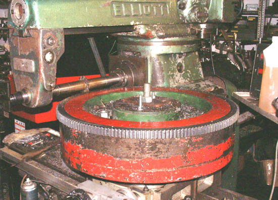 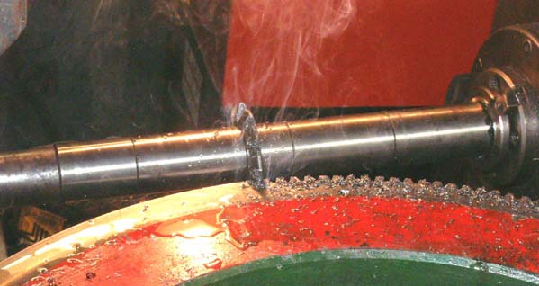 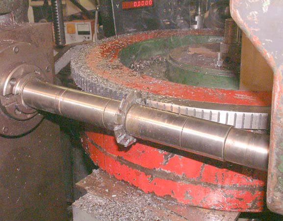 John S. |
| JasonB | 07/08/2011 14:16:40 |
25215 forum posts 3105 photos 1 articles | Just another thought can you use the dividing head in a vertical position to space the teeth and arrange a couple of substantial blocks either side of the cutter to clamp the gear blank to. That way you get the same accuracy of division that you had with the rest of the gears and the gear is supported rigidly as it would be on a large rotary table.
J |
| Andrew Johnston | 07/08/2011 23:02:08 |
7061 forum posts 719 photos | Thanks one and all for the advice. The engines as designed don't have real or dummy springs; just a rear axle that runs in a cast axle tube, that bolts to the hornplates. Being contrary I haven't made the hornplates yet. I intend to made a test bar to measure the centre to centre distances for the gear sets and then adjust the holes in the hornplates accordingly, should they not be to the calculated numbers. I had considered using the dividing head in vertical mode, but the gear would then be the best part of 12" up in the air. That would need some pretty substantial supports to counteract the horizontal cutting forces. With the rotary table the gear will only be about 3" above the milling table, and the rotary table itself will help resist the forces. JohnS: Thanks, I have seen those pictures on my trawl through the web on this subject, but I didn't know you were involved. I should have known better! Michael: That's a succinct summary of the issue, and you're right I don't need to worry! I just need to get on and cut the gears now. Regards, Andrew |
Please login to post a reply.
Magazine Locator
Want the latest issue of Model Engineer or Model Engineers' Workshop? Use our magazine locator links to find your nearest stockist!
Sign up to our Newsletter
Sign up to our newsletter and get a free digital issue.
You can unsubscribe at anytime. View our privacy policy at www.mortons.co.uk/privacy
Latest Forum Posts
- *Oct 2023: FORUM MIGRATION TIMELINE*
05/10/2023 07:57:11 - Making ER11 collet chuck
05/10/2023 07:56:24 - What did you do today? 2023
05/10/2023 07:25:01 - Orrery
05/10/2023 06:00:41 - Wera hand-tools
05/10/2023 05:47:07 - New member
05/10/2023 04:40:11 - Problems with external pot on at1 vfd
05/10/2023 00:06:32 - Drain plug
04/10/2023 23:36:17 - digi phase converter for 10 machines.....
04/10/2023 23:13:48 - Winter Storage Of Locomotives
04/10/2023 21:02:11 - More Latest Posts...
- View All Topics
Support Our Partners


Shopping Partners
Subscription Offer

Latest "For Sale" Ads
- Reeves** - Rebuilt Royal Scot by Martin Evans
by John Broughton
£300.00 - BRITANNIA 5" GAUGE James Perrier
by Jon Seabright 1
£2,500.00 - Drill Grinder - for restoration
by Nigel Graham 2
£0.00 - WARCO WM18 MILLING MACHINE
by Alex Chudley
£1,200.00 - MYFORD SUPER 7 LATHE
by Alex Chudley
£2,000.00 - More "For Sale" Ads...
Latest "Wanted" Ads
- D1-3 backplate
by Michael Horley
Price Not Specified - fixed steady for a Colchester bantam mark1 800
by George Jervis
Price Not Specified - lbsc pansy
by JACK SIDEBOTHAM
Price Not Specified - Pratt Burnerd multifit chuck key.
by Tim Riome
Price Not Specified - BANDSAW BLADE WELDER
by HUGH
Price Not Specified - More "Wanted" Ads...
Get In Touch!
Do you want to contact the Model Engineer and Model Engineers' Workshop team?
You can contact us by phone, mail or email about the magazines including becoming a contributor, submitting reader's letters or making queries about articles. You can also get in touch about this website, advertising or other general issues.
Click THIS LINK for full contact details.
For subscription issues please see THIS LINK.
Digital Back Issues


Donate

 Register
 Log-in
Model Engineer Magazine
- Percival Marshall
- M.E. History
- LittleLEC
- M.E. Clock

ME Workshop
- An Adcock
- & Shipley
- Horizontal
- Mill

Subscribe Now
- Great savings
- Delivered to your door

Pre-order your copy!
- Delivered to your doorstep!
- Free UK delivery!
All Forum Topics > Traction engines > Accuracy in Machining Large Gears