Forum sponsored by:

A New Dividing Plate for my Dividing Head
| JouniP | 08/07/2011 16:27:21 |
| 18 forum posts 5 photos | Hello I have a Dividing head with 60:1 reduction worm and 3 plates with 13, 17, 22, 24, 45, 49 23, 29, 37, 43, 53 19, 28, 31, 41, 47, 59 holes. The following divisions are possible: 2 through 60, 60 through 100 (except 63, 64, 81, 91, 99 and prime numbers) and 81 divisions between 100 and 360. I need to cut wheel with 64 teeth, which I can not cut. No big deal because I can make an extra dividing plate with 16, 32 or 48 holes, and with that I can divide by 64. I am too lazy to calculate is there any practical difference between 16, 32 or 48 holes and which one is best. Does someone have a opinion? Also, when I make a new dividing plate, can You recommend any other number of holes to drill? JP |
| John Stevenson | 08/07/2011 16:45:06 |
 5068 forum posts 3 photos | Posted by JouniP on 08/07/2011 16:27:21: I am too lazy to calculate is there any practical difference between 16, 32 or 48 holes and which one is best. Does someone have a opinion? JP I have an opinion but I'm also too lazy to post it  John S. |
| JouniP | 08/07/2011 18:01:04 |
| 18 forum posts 5 photos | English is not my mother language, as You perhaps has noticed. It's not always easy to me find right expressions. Perhaps I may try again. Is there any practical difference between 16, 32, or 48 holes in my problem. Of course I can make calculations myself, but that takes time. Perhaps someone already have sensible opinion? JP |
| John Stevenson | 08/07/2011 19:33:47 |
5068 forum posts 3 photos | JP, I did put a smiley at the end of my post. As regards your numbers any would do but the higher the better for the odd chance that one large number will not break down lower. As regards other number, and you may be lacking in space but 63, 127 and 25 come t mind.63 and 127 for metric translation gears and 25 because believe it or not a dividing head can't do 125 divisions or 250 divisions without a 25 hole circle. 125 or 250 is very common on feed screws with 8 or 4 tpi again very common on older British machines. John S. |
| JouniP | 08/07/2011 20:11:22 |
| 18 forum posts 5 photos | I noticed smiley and regret nuance of my post. Sorry. 127 (and 113) divisions would be useful but I can not find way to make new plate to make them. 25 holes is good advice. JP |
| alan frost | 09/07/2011 00:16:42 |
| 137 forum posts 3 photos | An old trick I admit to never trying is saving your old broken bandsaw blades and turning a wooden,aluminium, or steel disc to a diameter accomodating exactly the no. of teeth required, and using the teeth with a lashed up detent as an indexer. Guy Lautards bedside reader ( number two or three ) has a more sophisticated and probably more accurate method using ball bearings (I think ) spaced round a suitably sized perimeter ). There must be better ways-such as using CNC but I'm too old for such passing fads.
Don't see the need for them-for the benefit of regular readers the time is 00.12 (9th July ) and I've nearly half finished making my brush ring for an electric motor using a file. Started only just over a week ago-who needs CNC ?. Mind you I'm not rushing -stopped for a coffee yesterday.
PS If no-one comes up with a better way will look up Lautard method and post details. Rgds. Edited By alan frost on 09/07/2011 00:25:23 |
| alan frost | 09/07/2011 00:35:51 |
| 137 forum posts 3 photos | A ps. Don't know how you value your time but M.E. Tools (no connection ) produce some reasonably priced dividing plates which I seem to remember have extra rings of holes with useful numbers such as 25 and 127. My memory is not what it was-perhaps someone else can confirm ? |
| Richard Parsons | 09/07/2011 04:58:59 |
 645 forum posts 33 photos | The answer to your problem can be found in an earlier thread. This thread is called “Cutting a 365 tooth gear”.
|
| Andrew Johnston | 09/07/2011 11:17:00 |
 7061 forum posts 719 photos | There are several ways to achieve the required dividing plate. If we stick to the 16 holes needed for the job in hand, then the holes can be marked out by hand to a high degree of accuracy. How so? Any angle can be divided exactly in half using a compass and straight edge, no actual measurement needed. So, starting from a diamterical line just keep dividing by 2. The method expounded by Lautard is a good one, either directly, or used to generate a dividing plate. I hadn't heard about using ball bearings; in the edition I have he mentions using toolmakers buttons, but ball bearings would be cheaper and quicker. Of course a CNC mill can be used, but it's debatable as to whether it is quicker than using a manual method. It would be possible to use a rotary table to generate the holes, each increment is 5.625°, so not too onerous. Finally, any half decent DRO should have a bolt circle feature. I'm in the process of making a dividing plate with 63 and 69 holes. While I have the facilities to use any of the above methods I'll probably end up using the manual vertical mill and the DRO, as I think it will be quicker to set up than using the CNC mill. Regards, Andrew |
| Andrew Johnston | 10/07/2011 10:31:38 |
7061 forum posts 719 photos | Fired with enthusiasm I made my dividing plate yesterday afternoon. It's in alumimium, as I had an end of bar offcut of the right size, and it will only be used a couple of times, 2 off 69 tooth gears and 2 off 63 tooth gears. The OD is 6-3/8". All machining was done manually. 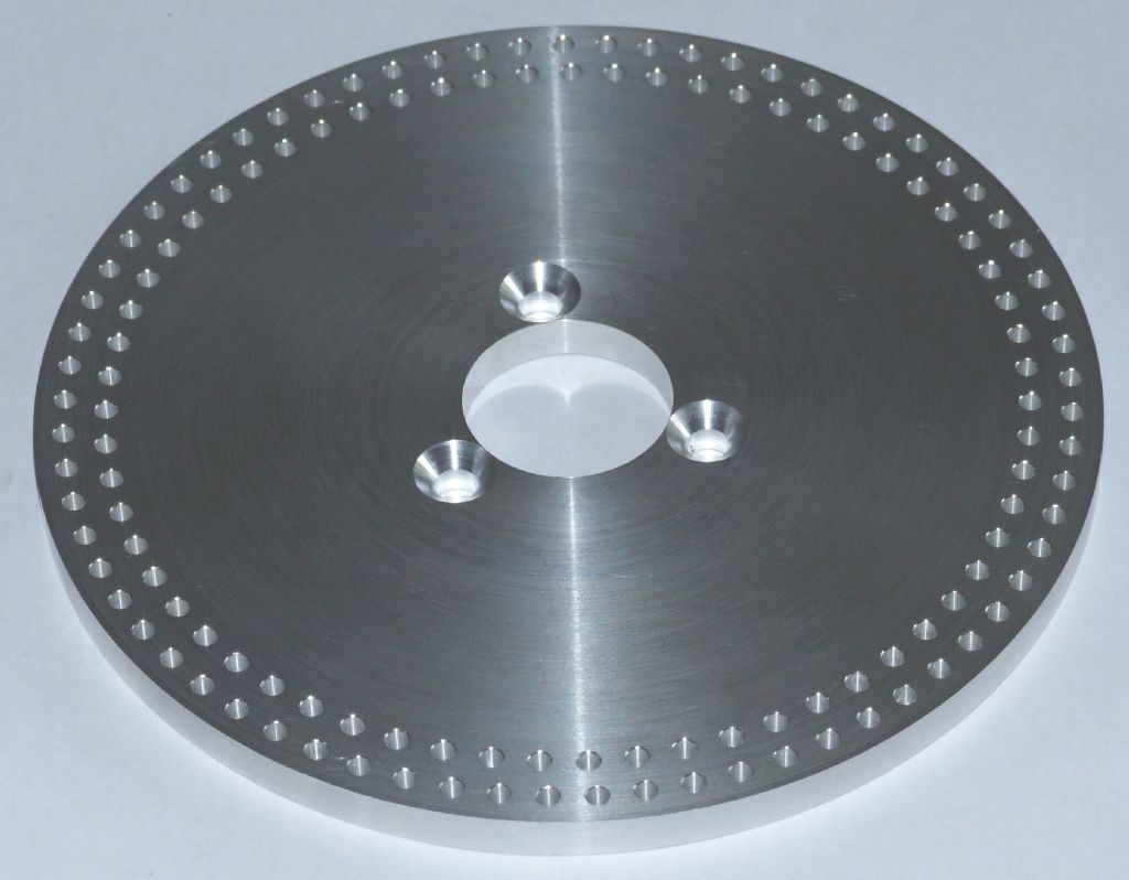 Regards, Andrew |
| alan frost | 10/07/2011 23:36:58 |
| 137 forum posts 3 photos | Nice looking job , pretty quick too |
| Sam Stones | 11/07/2011 04:17:45 |
 922 forum posts 332 photos |
Andrew, That’s very impressive. When you told us you would probably use the DRO, was that X and Y? If so, then what was your coordinate source. Regards, Sam |
| John Stevenson | 11/07/2011 07:35:35 |
5068 forum posts 3 photos | Sam, if it's anything like my DRO you centre the work up and set for X and Y zero's then punch in how many divisions and PCD. It then spits out two co-ordinates that take you to the first hole, just move until both read zero and drill. The arrow key they gives the co-ordinate out for the second hole, again move to all zero's and drill. So basically the co-ordinate source is in the DRO. Rinse and repeat. John S. |
| Sam Stones | 11/07/2011 08:08:39 |
922 forum posts 332 photos | What a wonderful gadget John,
Every home should have one.
But wait a minute, I've got exactly the same in my CAD package.
Sam
|
| John Stevenson | 11/07/2011 08:51:16 |
5068 forum posts 3 photos | CAD package. Dedicated computer program. Rough and ready Excel spreadsheet. Many ways to do the same job, none are wrong just that some methods are better suited to how you work. I am a big believer is doing a job the way that suits you and your equipment, no good saying use this gadget when no one else has one. I must admit though that when I come to use this bolt hole circle function on the DRO I have to get the book out for the exact method as I don't use it enough for the little quirks on keystrokes to stick in what's left of a brain. I must admit though I use CNC for all the plates I make. Doing these commercially in the quantity I do makes this an ideal job and if I had to do them by hand it would be a total pain and not enjoyable. A typical set of watch makers plates has 1,264 holes in them and I probably do 5 sets per day when they are running. John S. |
| Andrew Johnston | 11/07/2011 19:47:42 |
7061 forum posts 719 photos | Thanks for the kind words. I am pleased with the way it turned out; doesn't usually work that way for me! The starting offcut was 7" diameter and varied in thickness from 3/8" to 1/2". The final thickness was 5/16". Sequence of operations was: Mount the blank in the 4 jaw chuck roughly concentric and square. Machine the front face, outer diameter and drill and bore the central hole. Turn blank round in 4 jaw chuck, ensuring squareness to lathe axis. Face second side to required thickness. Mount the blank on parallels on the vertical mill; two clamps on the outside. Set the DRO so that 0,0 is the centre of the blank. We don't need any great accuracy here (a couple of thou is fine) so use a piece of silver steel in the drill chuck, indicate off the central hole, using a cigarette paper, and use the 1/2 function on the DRO to give the centre in each axis. Use the bolt function to drill and then countersink the three mounting holes. Insert a clamp in the central hole and remove the two outer clamps. Use the bolt function on the DRO to drill the two outer circles of 69 and 63 holes. Chamfer holes by hand with a countersink; job done. John S has the essence of the bolt function on the DRO. In my case you enter the centre (in this case 0,0 although it can be anywhere), the diameter of the circle, the number of holes, the starting angle (with 9 o'clock being zero) and then successive presses of the > button give you the location of each hole when the displays are zero'd. As Sam says you could get the X,Y co-ordinates of each hole from a CAD system. For dummies like me the bolt function is easier as you just mindlessly zero the displays for each hole, rather than have to set to a specific number. I've also hogged out some riser blocks for my dividing head, so no excuses now, I need to get on and cut the gears. Regards, Andrew |
| John Stevenson | 11/07/2011 21:52:29 |
5068 forum posts 3 photos | Posted by Andrew Johnston on 11/07/2011 19:47:42: the starting angle (with 9 o'clock being zero) Regards, Andrew Mine must be on British summer time as zero is at 3 o'clock. <g> John S. |
| Andrew Johnston | 11/07/2011 22:21:20 |
7061 forum posts 719 photos | Mine must be on British summer time as zero is at 3 o'clock. John S. Hmmm, didn't think of that; certainly another solution. Since each successive hole increments anti-clockwise I rather assumed that the starting angle from 0 was also positive anti-clockwise. Then again I am left-handed, and therefore sinister, so may be my mill is backwards, in true Dennis Wheatley fashion. Regards, Andrew
|
| Sam Stones | 12/07/2011 02:49:45 |
922 forum posts 332 photos |
In my CAD package (Keycreator), zero is also at 3 o’clock, and also counts ACW. This seems to gel with my memory of trigonometry. The first gear wheel I made for the skeleton clock back in the 70's was the Great Wheel. This brass wheel transfers the torque from the fusee upwards into the main gear train. At that time, I had a Myford ML7 and a home-made 40:1 dividing attachment with three dividing plates. DRO’s were a thing of the future. John Steven’s drawing describes the 96 tooth wheel OD as 2 23/32" (or about 69mm), and 7/32" (5.5mm) wide. I turned the blank to size (as you would), and ground and hardened a piece of round silver steel, the end of which had the all important tooth profile. This was my fly cutter. In a Melbourne summer, there can be a lot of flies around.
I began cutting grooves between the teeth, gaining confidence tooth by tooth as the job progressed. At last I was cutting the one remaining groove, and decided as a final check to `drop’ into the first groove. Whoops! What’s this ‘ere. The first tooth disappeared before my very eyes, which should have been better trained for such serious work. Further investigations showed that I didn’t actually have the right number of holes in the dividing plate to `do’ 96 teeth, and had in fact chosen the wrong combination. My luck was `in’ however, because, of all the gears in the clock this, and its mating lantern pinion, were the only two gears where the tooth count didn’t really matter.
 So, as with many traps for new players, the Great Wheel (and the Maintaining Wheel) ended up with only 94 teeth. Regards to all,
Sam |
| Andrew Johnston | 01/08/2011 20:22:10 |
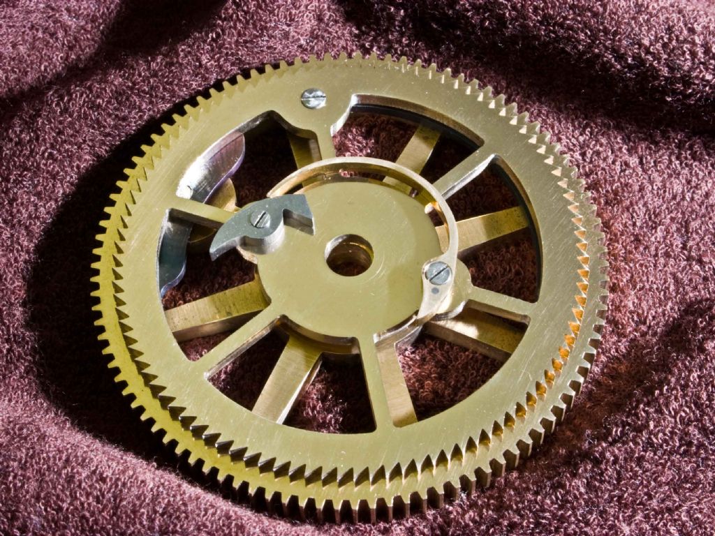
7061 forum posts 719 photos | Just to round off part of the thread I have now started cutting the gears using my new division plate. Two sets, each with one gear with 63 teeth and one with 69 teeth. Here's the division plate in position: 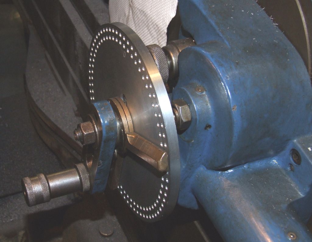 The larger of the two gears being cut: 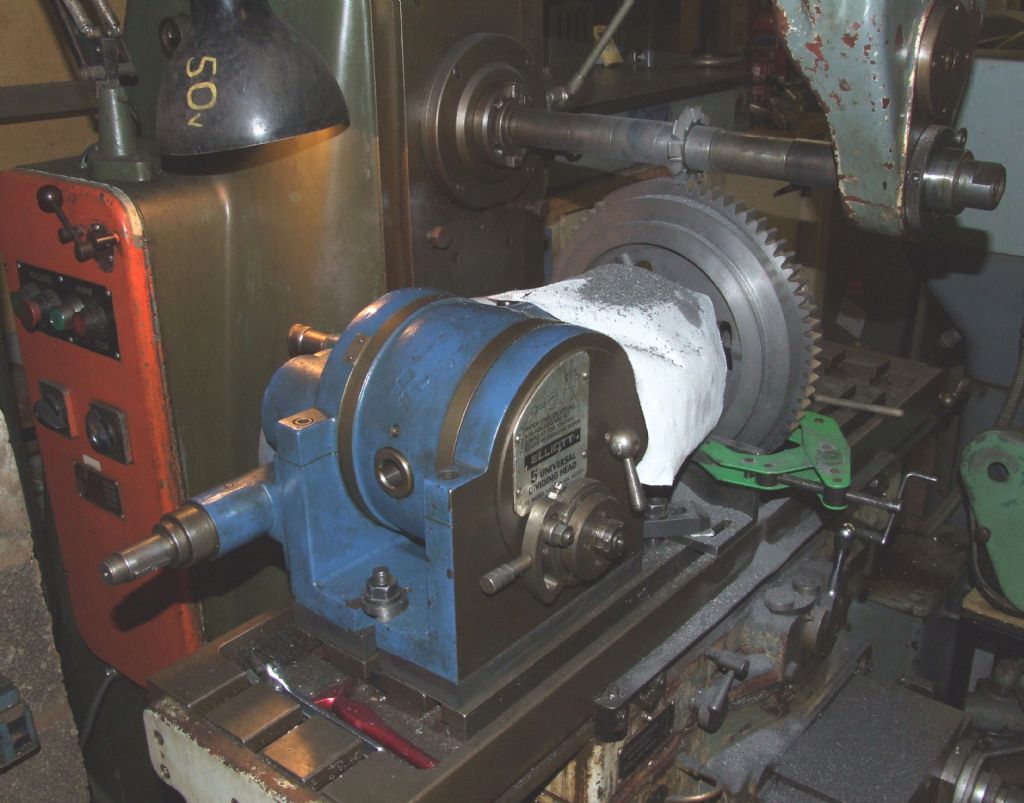 And finally the two gears, together with the part machined differential centre: 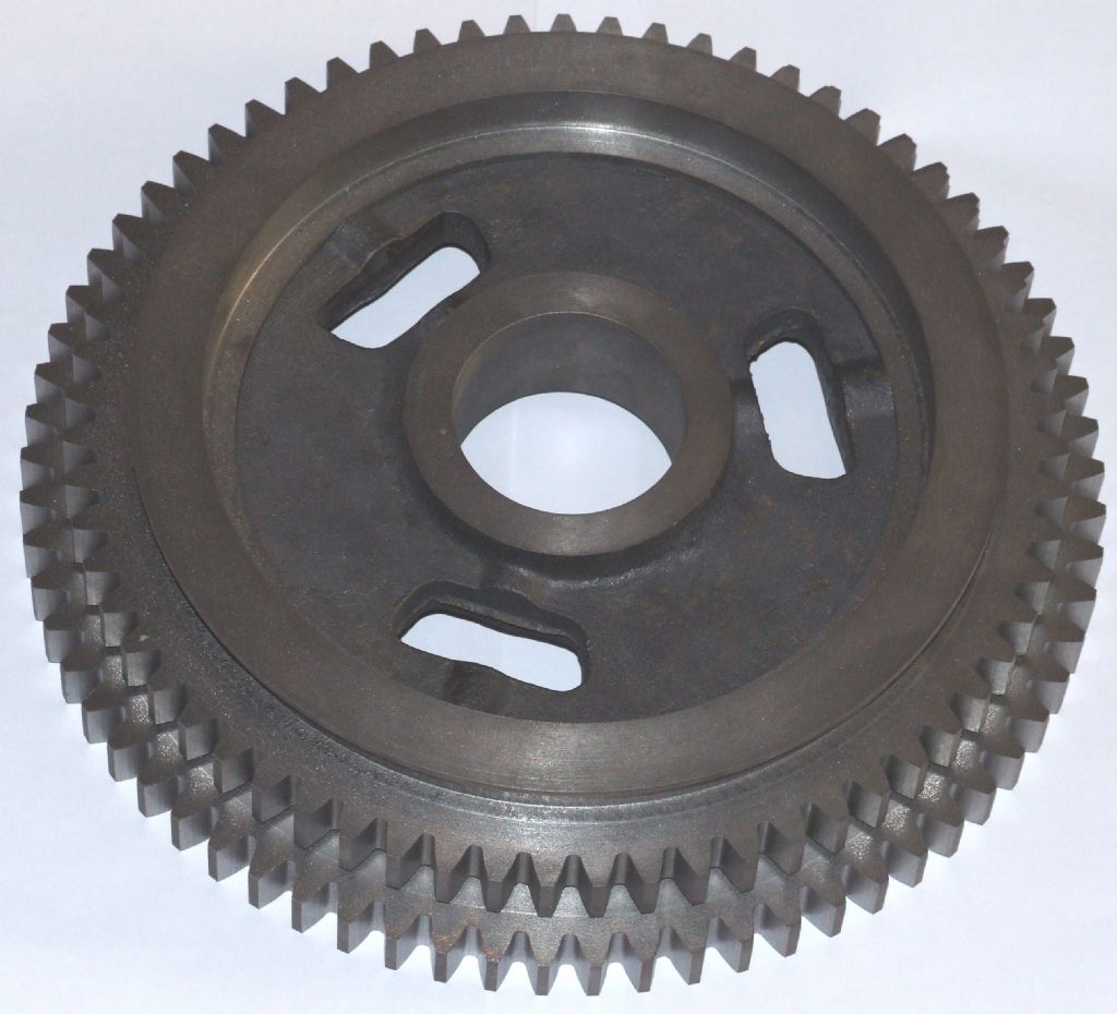 For reference the larger gear is a shade under 12" in diameter. The more observant will note the green clamp in the picture of the gear cutting in progress. This is to stop the gear rotating during cutting. First time round I optimistically assumed that the dividing head spindle lock and tailstock would be sufficient, given that the cutting forces, in theory, are along the x axis. Sadly my optimism was misplaced, and on the 60th or so tooth the gear slipped by about 20 thou on the periphery. I've been round and recut the gear, and I'm sure that in practice it would work, but I'm not happy with it, so I've ordered a new casting. An expensive lesson learnt.  Regards, Andrew |
Please login to post a reply.
Magazine Locator
Want the latest issue of Model Engineer or Model Engineers' Workshop? Use our magazine locator links to find your nearest stockist!
Sign up to our Newsletter
Sign up to our newsletter and get a free digital issue.
You can unsubscribe at anytime. View our privacy policy at www.mortons.co.uk/privacy
Latest Forum Posts
- *Oct 2023: FORUM MIGRATION TIMELINE*
05/10/2023 07:57:11 - Making ER11 collet chuck
05/10/2023 07:56:24 - What did you do today? 2023
05/10/2023 07:25:01 - Orrery
05/10/2023 06:00:41 - Wera hand-tools
05/10/2023 05:47:07 - New member
05/10/2023 04:40:11 - Problems with external pot on at1 vfd
05/10/2023 00:06:32 - Drain plug
04/10/2023 23:36:17 - digi phase converter for 10 machines.....
04/10/2023 23:13:48 - Winter Storage Of Locomotives
04/10/2023 21:02:11 - More Latest Posts...
- View All Topics
Support Our Partners


Shopping Partners
Subscription Offer

Latest "For Sale" Ads
- Reeves** - Rebuilt Royal Scot by Martin Evans
by John Broughton
£300.00 - BRITANNIA 5" GAUGE James Perrier
by Jon Seabright 1
£2,500.00 - Drill Grinder - for restoration
by Nigel Graham 2
£0.00 - WARCO WM18 MILLING MACHINE
by Alex Chudley
£1,200.00 - MYFORD SUPER 7 LATHE
by Alex Chudley
£2,000.00 - More "For Sale" Ads...
Latest "Wanted" Ads
- D1-3 backplate
by Michael Horley
Price Not Specified - fixed steady for a Colchester bantam mark1 800
by George Jervis
Price Not Specified - lbsc pansy
by JACK SIDEBOTHAM
Price Not Specified - Pratt Burnerd multifit chuck key.
by Tim Riome
Price Not Specified - BANDSAW BLADE WELDER
by HUGH
Price Not Specified - More "Wanted" Ads...
Get In Touch!
Do you want to contact the Model Engineer and Model Engineers' Workshop team?
You can contact us by phone, mail or email about the magazines including becoming a contributor, submitting reader's letters or making queries about articles. You can also get in touch about this website, advertising or other general issues.
Click THIS LINK for full contact details.
For subscription issues please see THIS LINK.
Digital Back Issues


Donate

 Register
 Log-in
Model Engineer Magazine
- Percival Marshall
- M.E. History
- LittleLEC
- M.E. Clock

ME Workshop
- An Adcock
- & Shipley
- Horizontal
- Mill

Subscribe Now
- Great savings
- Delivered to your door

Pre-order your copy!
- Delivered to your doorstep!
- Free UK delivery!
All Forum Topics > Workshop Techniques > A New Dividing Plate for my Dividing Head