Member postings for Stub Mandrel
Here is a list of all the postings Stub Mandrel has made in our forums. Click on a thread name to jump to the thread.
| Thread: Machining a Cylinder from the Solid |
| 23/01/2010 19:59:14 |
The cylinder shape was now starting to appear. I returned it, still in the chuck, to the lathe and turned down the flanges to size. One of these had to be done using a parting tool. I was nervous about taking an interrupted cut through the surface of an iron casting with a parting tool. Fortunately the minimal skin and excellent cutting properties of the bar meant that I had no difficulty. In retrospect it might have been wise to take the 'skin' off the bar before setting it up eccentrically, just in case. 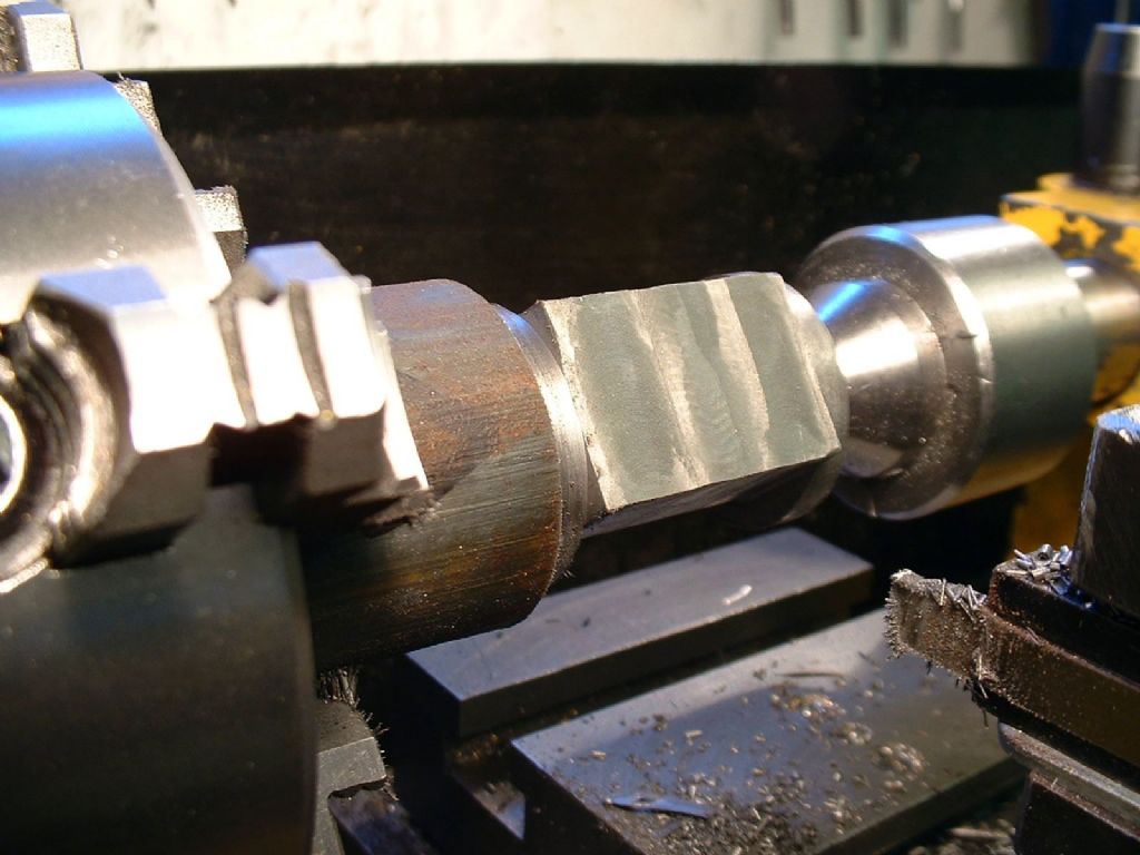 |
| 23/01/2010 19:56:44 |
4. Finally, the rotary table was locked with what would become the slide face uppermost. I made the mistake of removing all the material in one go and didn't get a very good finish, but didn't realise this immediately. This meant I had to re-finish the valve face later. 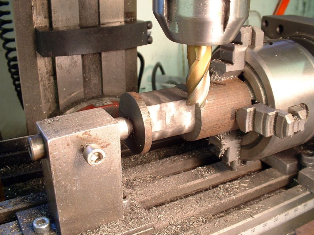 Edited By Neil on 23/01/2010 19:58:22 |
| 23/01/2010 19:55:37 |
3. Measuring across the diameter of the curved surface it was apparent that it needed to be reduced by just over 3/8". This was done in just two cuts feeding in 3/32 each time. For the first cut the depth was much more than 3/32" once the cylinder had been rotated - about 1/4" in fact, but this did not cause any problems. As well as machining the curve around the back of the cylinder, the cross slide was used to form the sides of the valve faces. For these final cuts across the sides of the cylinder the rotary table was locked. 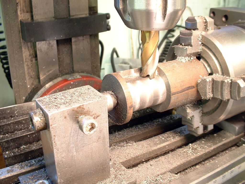 |
| 23/01/2010 19:54:04 |
| Still in the chuck, I moved the whole caboodle onto a rotary table on the milling machine, supporting the bar with a tailstock in the pre-drilled centre. I had previously adjusted the rotary table to minimise backlash. I then used a 1/2" four flute endmill to shape the outside of the cylinder. For the record, I ran the mill at 900rpm. The milling was carried out in the following stages: 1. Line up the centre line of the cutter with that of the cylinder. Set index to zero and note the reading when approaching from the other direction to allow for backlash. Orient the bar so the 'low point' (which will become the far side of the cylinder from the valve face) is on top. Take two skimming cuts at 3/4" spacing to mark the width of the inner flange faces 1 1/4" inches apart. Index reading in one direction set to zero, note that in the other direction (note this is not the expected value of 1.25”, due to backlash). 2. Set the cutter over to one end of the cut and on the cylinder centre line. Gently rotate the work through just over 90° (not critical). Set the rotary table index to zero. Move the cutter across to the other flange and turn the table back 183°. Return to the first flange and then retract the cross slide to clear the cutter from the work. One can now see the indication of where the curved surface of the bar has to be machined away, and defined what will be the start of the slightly tapering (to simulate the draft on a casting) flat sides of the valve face 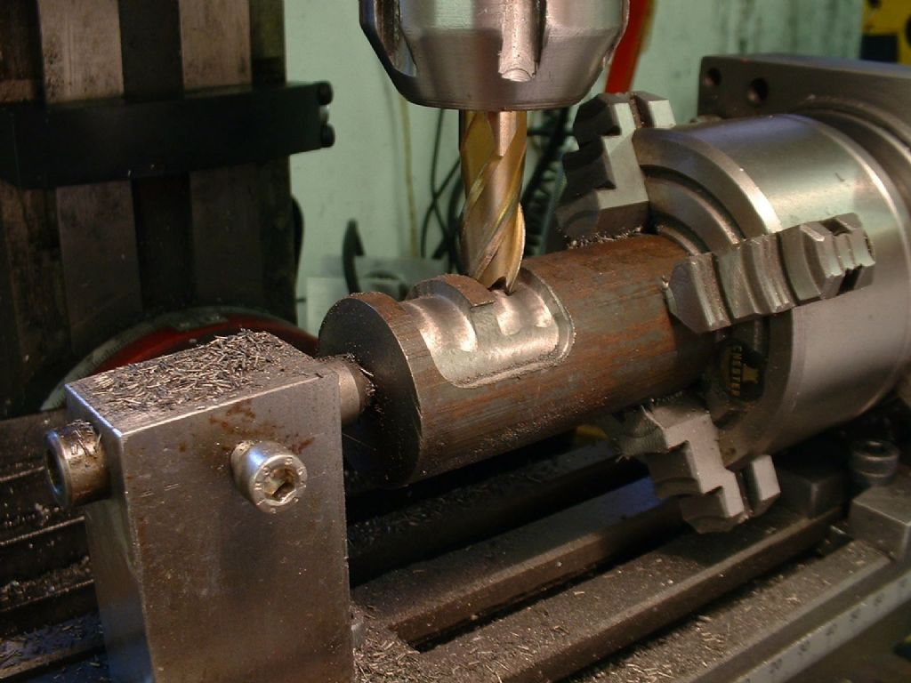 |
| 23/01/2010 19:52:37 |
| A few years ago I worked out a method for easily machining flanged cylinders from solid cast iron bar. There is very little waste, and is a good way to use up bar ends so I thought folk might be interested in a photo-guide. The example cylinder in question has a nice shape, being fairly tall and having angled sides that taper into the valve face. This shape lends itself to being machined rather more easily than when the valve face is joined to the cylinder by a marked step. I used Corel Draw, a vector drawing programme, rather than full CAD, to produce my drawings. One of the advantages of using the computer is being able to move things around to see if they fit. In this case I was able to see that there was plenty of room for the cylinder, including the valve face, in a 1 1/4" continuous-cast meehanite bar. This was obtained from College engineering and machined beautifully with no hard spots and very little 'skin'. An eccentricity of roughly 9/64" would leave a machining allowance all around the casting. I set the bar in my 4-jaw chuck using the tip of a tool in the toolpost and a 9/64” drill to gauge the offset. Greater accuracy was not needed. I then centre drilled the bar and faced the end, supporting it with a half-centre (photo 1). 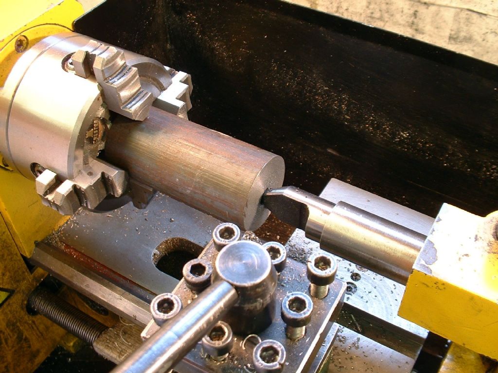 |
| Thread: Quality of Castings |
| 20/01/2010 21:40:37 |
Thanks guys! Neil |
| Thread: Search Fields |
| 20/01/2010 21:39:34 |
A search facility for images would be useful as well! Neil |
| Thread: Milling Tools |
| 20/01/2010 21:29:24 |
Making tools brings twice the satisfaction; you get to make it, then you get to use it. I advise investing in a good vice/clamps and plenty of milling cutters that all fit the same holder system. You can make almost any other accessory you need, if you should choose to do so. Neil Oops sorry for the double post - Firefox crashed and I didn't think I had sent the first version. Edited By Neil on 20/01/2010 21:31:35 |
| 20/01/2010 21:25:11 |
I must be honest, i get as much pleasure from making tooling as making models. More I suppose, because you get the pleasure over again from using the tools. My dividing head mounts my mini lathe chuck. The spindle and body were two huge lumps of cast iron from college engineering, and I 'free hobbed' the gear at a second attempt (number 1 had 61 teeth!) It looks a bit agricultural, but it does the job. I also made a boring head and a ER25 collet holder (which was in ME about 9 years ago). I suggest putting your money into one or two solid vices, good milling cutters and standardising on one type of holder. You can make almost anything else, if you wish. Neil |
| Thread: B & Q Steel stock |
| 20/01/2010 21:03:27 |
I was looking at the 'extended range' in the Burton B&Q. Some useful stuff, but a lot of the DIY staples are cheaper in Wickes across the way  Was a bit disappointed to find the Metal Supermarkets are in the USA , but then discovered the West Brom branch isn't too far to get to from work. But I'd love to track down a good cheap source of reasonable sized offcuts (e.g. up to 2" bar) in the Burton area. Any ideas? Thanks Neil Edited By Neil on 20/01/2010 21:09:49 |
| Thread: Tachometer design |
| 20/01/2010 20:10:56 |
Hi Les, Good luck! Personally I would rather see relevant electronic projects than reams of g-code or lone descriptions of how to use computer packages that are about 3-d modelling, not design or production. I have made a couple of very similar units, but I used an AVR - so it must be better than one made using a PIC eh?  It may be of interest that I timed the delay between pulses and took the reciprocal to get rpm, rather than counting pulses. I assume that's how you cope with the need to regularly update the display at low speeds. The one bit of cleverness was detecting sudden decelaration caused by back emf braking to spot the difference between a slow-down (which is more gradual) and a (rapid) stop. I use a hall effect switch, it gives a much cleaner logic-level signal than the 'ratiometric' sensors. I waved some details of this and a DRO at an earlier editor of ME, but he felt it was outside the publication's range, due to the pcb issues and the need to have someone programme the micros (I would happily have done this for little more than cost). These days the PCB design as a suitable file to print out on transparency to make PCBs or (even on paper for the iron on method) could be posted here, as could code for programming micros. I would guess that AVR (or even PIC) based projects would be within the ability of 50% of MEW/ME readers - but I doubt that proportion of us could build a gold medal winner Neil Edited By Neil on 20/01/2010 20:13:37 Edited By Neil on 20/01/2010 20:31:25 |
| Thread: Belt drive for mini mill / x2 sieg arc |
| 20/01/2010 19:43:05 |
Interesting stuff. i bought one of the first batch of X2's - I think it's number 3 from memory. Ketan mentioned unspecified mods to solve problems other distributors had. I note that they don't do the X2 any more. Although its the 'sister' of the mini lathe it seems to be flawed. Unlike a lathe, milling seems to demand both speed and rigidity. I can't do over-sized or heavy jobs by just slowing it all down, like I do with the lathe. I haven't bust any gears, but keep it in low gear all the time, but some mounting screws came lose and the controller board shorted out on the main pillar. Arc replaced it FOC, but I got a note published in ME or MEW advising people to pop some insulation tape in the control box, just in case. I have considered the metal gear conversion for my mini lathe, but having done the bearing swap I don't really look forward to taking it all apart again... there's plenty of grease in there now, though there wasn't at first, just plastic dust! (it was a clarke machine). One mod I have done (besides 3-axis DRO's) is to scrape the fit between the pillar angle bracket and the base. the contact area was only about 20% and now its more like 80% and spread over the whole area. It wasn't pretty scraping, but it made the machine much more rigid. I haven't heard of anyone else doing this. I am considering using an epoxy-base resin to make it totally solid, and possibly doing something to take the swivel out of the swivel joint on the pillar. Edited By Neil on 20/01/2010 19:52:43 |
| Thread: Signature Files |
| 14/01/2010 19:35:06 |
Seconded! Regards Neil |
| Thread: Digital editions of Model Engineer and Model Engineers' Workshop. |
| 14/01/2010 19:25:40 |
(You want Young's Modulus for TP304L stainless and you ain't going to get it for free!) Call yerself a model engineer? You should be able to measure it for yourself More seriously, 100+ years of ME online would be a great thing. I am slowly modelling a Vickers Vulcan, and found an on-line facsimile of a 1930's article (in The Aeroplane IIRC) about the still-incomplete prototype, with isometric views of key parts and a three-view to scale and much bigger than a tiny version I already had. There's no way I would even have known that source existed. If the online issues are 'googleable' they could bring many new converts to ME and the hobby. I can't afford a full set of ME, but I'd love to be able to pick up the sources for some key articles - even see some pages from back copies I do have properly, not sucked into the binding! I'm especially interested in E.T.Westbury's writings, I think he was a greater writer than even LBSC, dare I say it (spits, crosses himself, sprinkles salt and turns round three times) I think the existing sub should entitle you to a certain level of access free (2 or 3 issues a month?) then a suitable micro-charge for more? One big appeal - David, may we have the first few issues of ME online, plus maybe the 50, 100 and a few other anniversaries or key dates? Cheers, Neil |
| Thread: Stuart Vertical Engines - The real history ? |
| 14/01/2010 19:09:25 |
I recently posted pictures of couple of full size engines in my albums - even the models are real engines This Tangye engine at the Black Country Museum is not too far from a Stuart 10V at all! 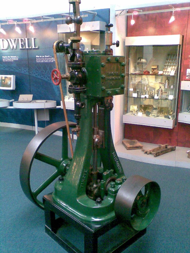 There are truckloads of engine about, if you look |
| Thread: A simple oscillating steam engine |
| 13/01/2010 21:57:45 |
Very pretty! Full marks for presentation. |
| Thread: Norden |
| 13/01/2010 21:53:46 |
This is my best effort to date. It''s based on a sshort description and a tiny drawing in a 1940s issue of ME. The original was from a mill in Nordern, Lancashire. Can anyone tell me more about this type of engine, and spot any errors I made guessing the details? Cheers Neil |
| Thread: Albums |
| 13/01/2010 20:56:53 |
I'm enjoying uploading a selection of pictures to various albums, despite the website timing out quite a lot - is it the snow? I can't see any 'voting' section, but I think it would be good if we could comment on each other's work. Praise and constructive criticism (hopefully!) How broad can we go? I've posted a couple of boat models and a few pics of full size steam engines, as well as mostly model engineering - I want to give a flavour of all my modelling interests. One criticism - there needs to be some sort of search facility, also a random selection of thumbnails somewhere, so everyone's pictures get profiled. Finally, can we have auto-signatures for our posts? Cheers Neil Edited By Neil on 13/01/2010 20:58:03 |
| Thread: Quality of Castings |
| 11/01/2010 22:14:41 |
Am I alone in despairing about the quality of castings available from some suppliers? I won't mention names but the two ME suppliers nearest to me one produces castings that are clean and crisp, the other is willing to pass on bits of tatty metal that look like the patterns were chewed by a dog. I have had some castings made from my own patterns, and after some good advice the patterns are getting a bit better too! But it is so hard to get hold of a foundry that will produce castings, at any price. I have a half-finished pattern for a tractor bell-casing at 4" scale; does anyone know where I could get this cast for a reasonable price? I really need to get advice on the pattern and core before I go any further. Cheers Neil |
Magazine Locator
Want the latest issue of Model Engineer or Model Engineers' Workshop? Use our magazine locator links to find your nearest stockist!
Sign up to our Newsletter
Sign up to our newsletter and get a free digital issue.
You can unsubscribe at anytime. View our privacy policy at www.mortons.co.uk/privacy
Latest Forum Posts
- *Oct 2023: FORUM MIGRATION TIMELINE*
05/10/2023 07:57:11 - Making ER11 collet chuck
05/10/2023 07:56:24 - What did you do today? 2023
05/10/2023 07:25:01 - Orrery
05/10/2023 06:00:41 - Wera hand-tools
05/10/2023 05:47:07 - New member
05/10/2023 04:40:11 - Problems with external pot on at1 vfd
05/10/2023 00:06:32 - Drain plug
04/10/2023 23:36:17 - digi phase converter for 10 machines.....
04/10/2023 23:13:48 - Winter Storage Of Locomotives
04/10/2023 21:02:11 - More Latest Posts...
- View All Topics
Support Our Partners


Shopping Partners
Subscription Offer

Latest "For Sale" Ads
- Reeves** - Rebuilt Royal Scot by Martin Evans
by John Broughton
£300.00 - BRITANNIA 5" GAUGE James Perrier
by Jon Seabright 1
£2,500.00 - Drill Grinder - for restoration
by Nigel Graham 2
£0.00 - WARCO WM18 MILLING MACHINE
by Alex Chudley
£1,200.00 - MYFORD SUPER 7 LATHE
by Alex Chudley
£2,000.00 - More "For Sale" Ads...
Latest "Wanted" Ads
- D1-3 backplate
by Michael Horley
Price Not Specified - fixed steady for a Colchester bantam mark1 800
by George Jervis
Price Not Specified - lbsc pansy
by JACK SIDEBOTHAM
Price Not Specified - Pratt Burnerd multifit chuck key.
by Tim Riome
Price Not Specified - BANDSAW BLADE WELDER
by HUGH
Price Not Specified - More "Wanted" Ads...
Get In Touch!
Do you want to contact the Model Engineer and Model Engineers' Workshop team?
You can contact us by phone, mail or email about the magazines including becoming a contributor, submitting reader's letters or making queries about articles. You can also get in touch about this website, advertising or other general issues.
Click THIS LINK for full contact details.
For subscription issues please see THIS LINK.
Digital Back Issues


Donate

 Register
 Log-in
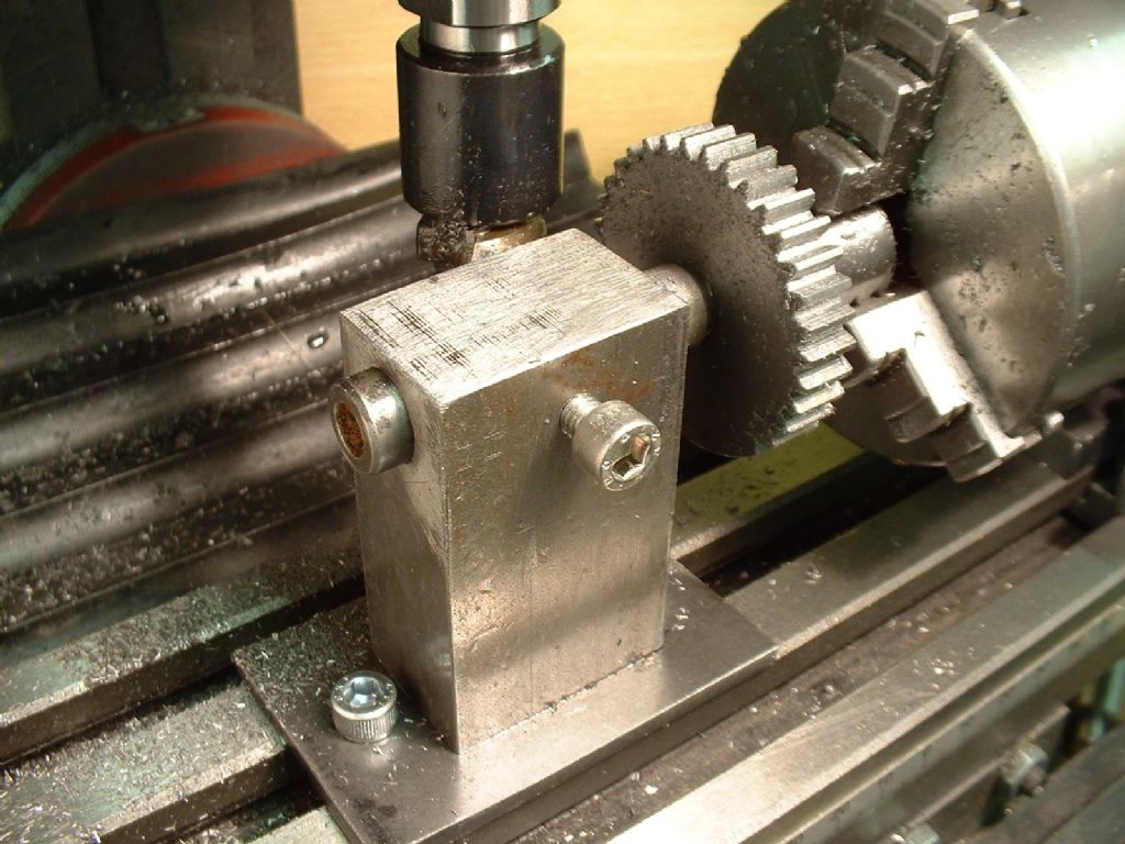
Model Engineer Magazine
- Percival Marshall
- M.E. History
- LittleLEC
- M.E. Clock

ME Workshop
- An Adcock
- & Shipley
- Horizontal
- Mill

Subscribe Now
- Great savings
- Delivered to your door

Pre-order your copy!
- Delivered to your doorstep!
- Free UK delivery!