Forum sponsored by:

Machining a Cylinder from the Solid
| Stub Mandrel | 23/01/2010 19:52:37 |
 4318 forum posts 291 photos 1 articles | A few years ago I worked out a method for easily machining flanged cylinders from solid cast iron bar. There is very little waste, and is a good way to use up bar ends so I thought folk might be interested in a photo-guide. The example cylinder in question has a nice shape, being fairly tall and having angled sides that taper into the valve face. This shape lends itself to being machined rather more easily than when the valve face is joined to the cylinder by a marked step. I used Corel Draw, a vector drawing programme, rather than full CAD, to produce my drawings. One of the advantages of using the computer is being able to move things around to see if they fit. In this case I was able to see that there was plenty of room for the cylinder, including the valve face, in a 1 1/4" continuous-cast meehanite bar. This was obtained from College engineering and machined beautifully with no hard spots and very little 'skin'. An eccentricity of roughly 9/64" would leave a machining allowance all around the casting. I set the bar in my 4-jaw chuck using the tip of a tool in the toolpost and a 9/64” drill to gauge the offset. Greater accuracy was not needed. I then centre drilled the bar and faced the end, supporting it with a half-centre (photo 1). 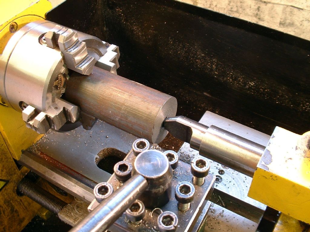 |
| Stub Mandrel | 23/01/2010 19:54:04 |
4318 forum posts 291 photos 1 articles | Still in the chuck, I moved the whole caboodle onto a rotary table on the milling machine, supporting the bar with a tailstock in the pre-drilled centre. I had previously adjusted the rotary table to minimise backlash. I then used a 1/2" four flute endmill to shape the outside of the cylinder. For the record, I ran the mill at 900rpm. The milling was carried out in the following stages: 1. Line up the centre line of the cutter with that of the cylinder. Set index to zero and note the reading when approaching from the other direction to allow for backlash. Orient the bar so the 'low point' (which will become the far side of the cylinder from the valve face) is on top. Take two skimming cuts at 3/4" spacing to mark the width of the inner flange faces 1 1/4" inches apart. Index reading in one direction set to zero, note that in the other direction (note this is not the expected value of 1.25”, due to backlash). 2. Set the cutter over to one end of the cut and on the cylinder centre line. Gently rotate the work through just over 90° (not critical). Set the rotary table index to zero. Move the cutter across to the other flange and turn the table back 183°. Return to the first flange and then retract the cross slide to clear the cutter from the work. One can now see the indication of where the curved surface of the bar has to be machined away, and defined what will be the start of the slightly tapering (to simulate the draft on a casting) flat sides of the valve face 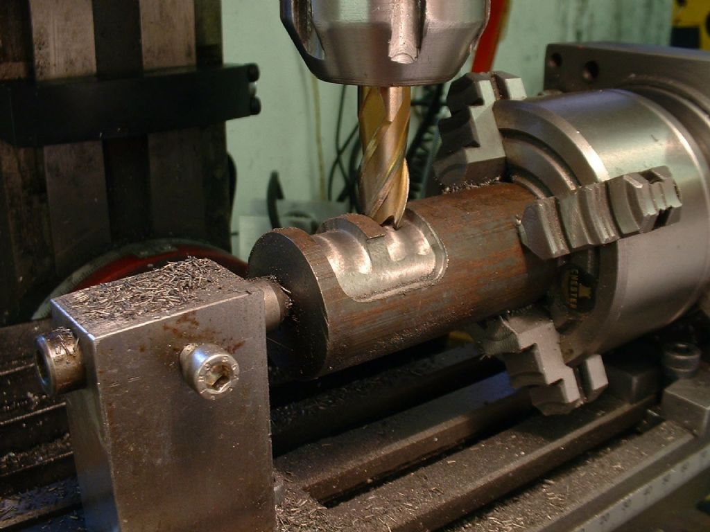 |
| Stub Mandrel | 23/01/2010 19:55:37 |
4318 forum posts 291 photos 1 articles | 3. Measuring across the diameter of the curved surface it was apparent that it needed to be reduced by just over 3/8". This was done in just two cuts feeding in 3/32 each time. For the first cut the depth was much more than 3/32" once the cylinder had been rotated - about 1/4" in fact, but this did not cause any problems. As well as machining the curve around the back of the cylinder, the cross slide was used to form the sides of the valve faces. For these final cuts across the sides of the cylinder the rotary table was locked. 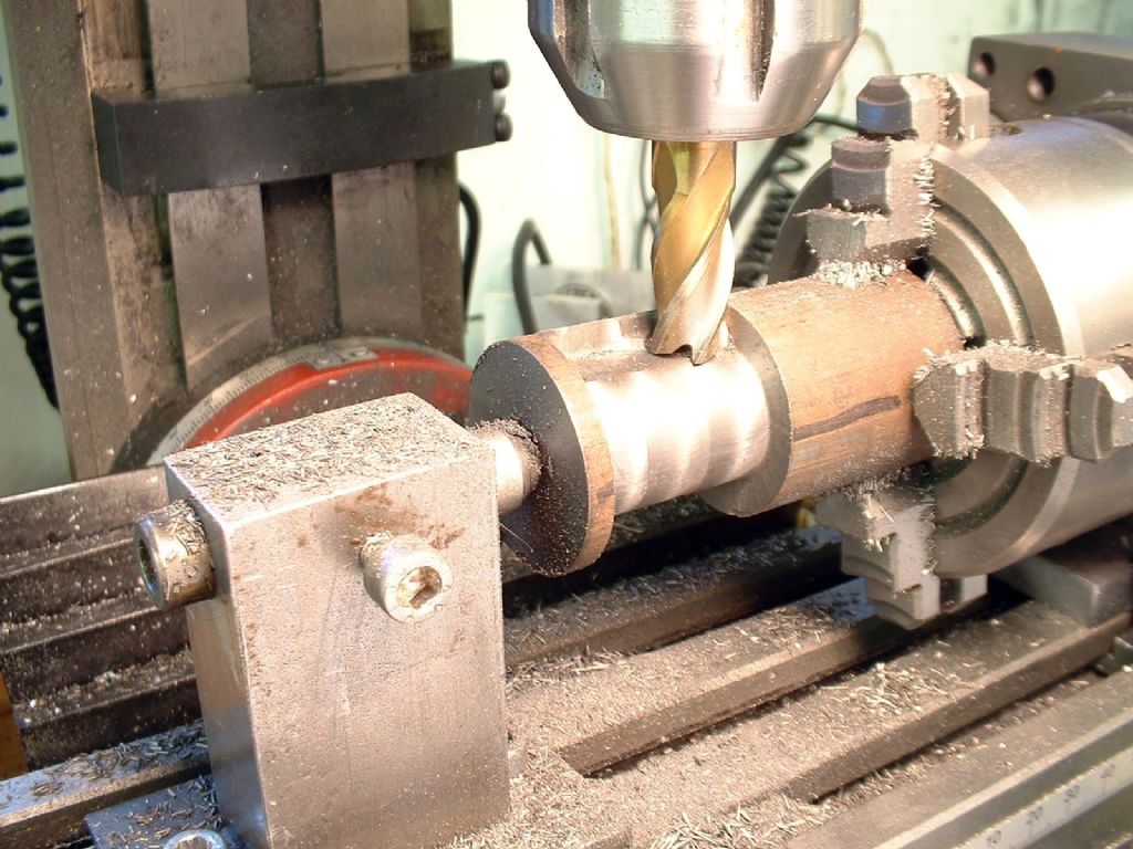 |
| Stub Mandrel | 23/01/2010 19:56:44 |
4318 forum posts 291 photos 1 articles | 4. Finally, the rotary table was locked with what would become the slide face uppermost. I made the mistake of removing all the material in one go and didn't get a very good finish, but didn't realise this immediately. This meant I had to re-finish the valve face later. 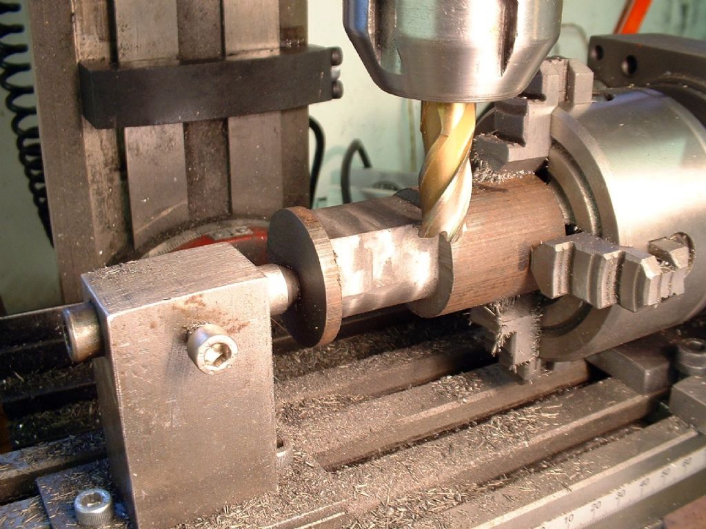 Edited By Neil on 23/01/2010 19:58:22 |
| Stub Mandrel | 23/01/2010 19:59:14 |
4318 forum posts 291 photos 1 articles | The cylinder shape was now starting to appear. I returned it, still in the chuck, to the lathe and turned down the flanges to size. One of these had to be done using a parting tool. I was nervous about taking an interrupted cut through the surface of an iron casting with a parting tool. Fortunately the minimal skin and excellent cutting properties of the bar meant that I had no difficulty. In retrospect it might have been wise to take the 'skin' off the bar before setting it up eccentrically, just in case. 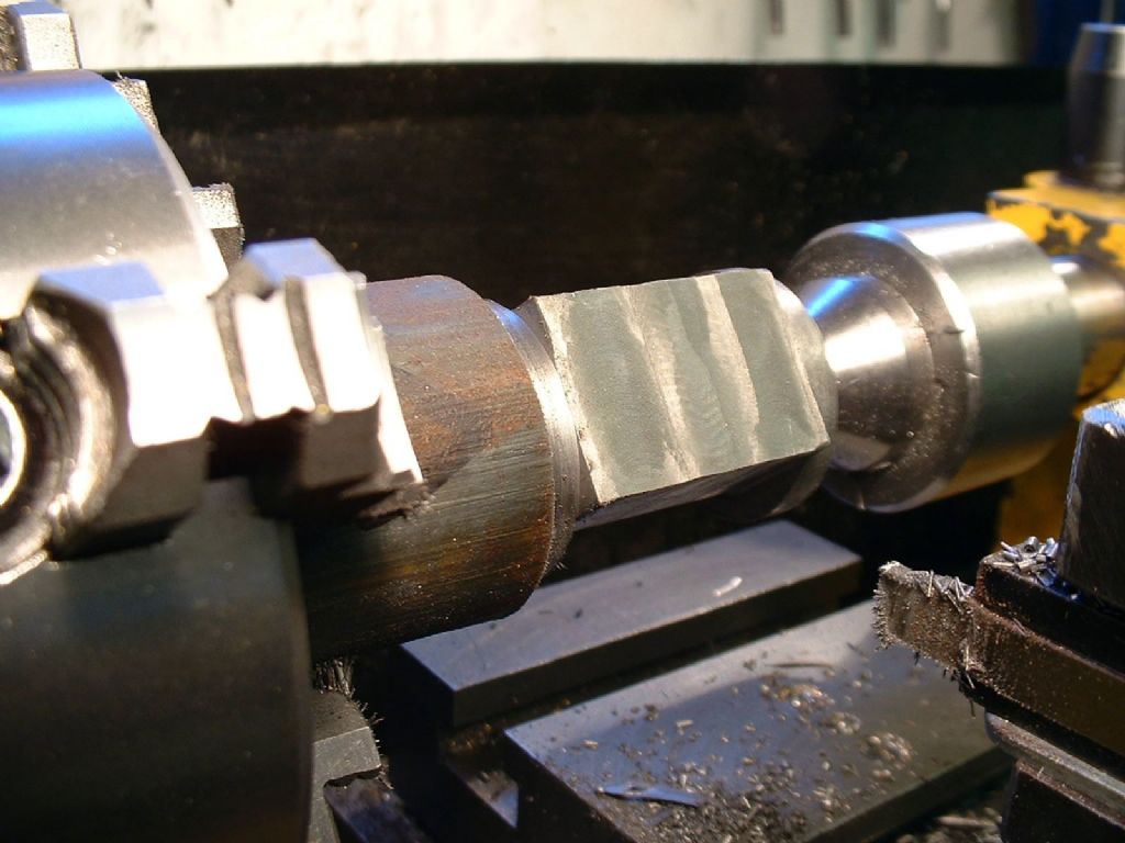 |
| Stub Mandrel | 23/01/2010 20:02:58 |
4318 forum posts 291 photos 1 articles | I decide it would be sensible to drill and then bore the cylinder while it was set up accurately centred in the chuck. I went up using several drill sizes in order to avoid any risk of a drill jamming and spoiling the set up. Final boring was done dead slow with cutting oil and the tip of the boring tool stoned to a gentle curve. The reward was the lovely satin grey finish that is ideal for a steam cylinder. 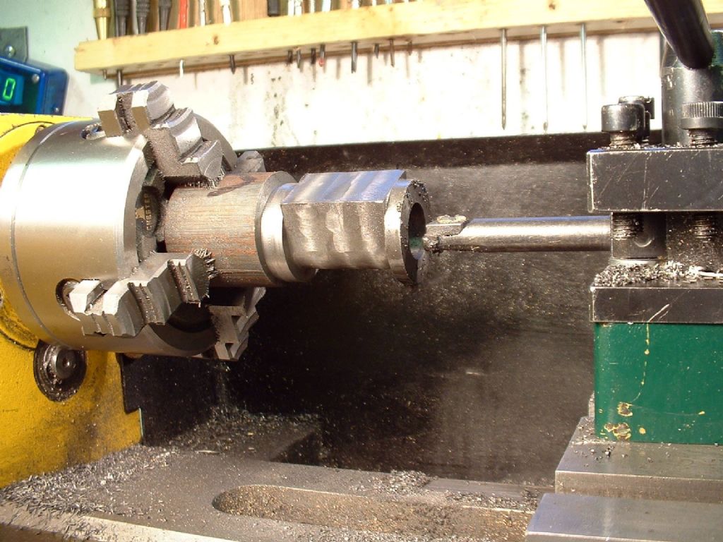 |
| Stub Mandrel | 23/01/2010 20:06:43 |
4318 forum posts 291 photos 1 articles | The cylinder bore was given as 9", which scaled to 3/4" at 1:12 scale. This would have left the sides of the cylinder 1/16" thick at most. I felt this did not leave much of a margin for error or strength. The information also stated that this was an estimate, so I decided there was no reason why the bore could just as easily have been 8" on the original engine, and therefore bored the cylinder to 0.667". I used the half-center again and reduced the top flange to 3/16 thick, then took away all support and parted off the cylinder leaving the bottom flange the same thickness. It parted away leaving a small ring of metal attached to he end of the bore. This was so thin it broke off neatly under thumb pressure. I gently bevelled the cut edge with emery paper. 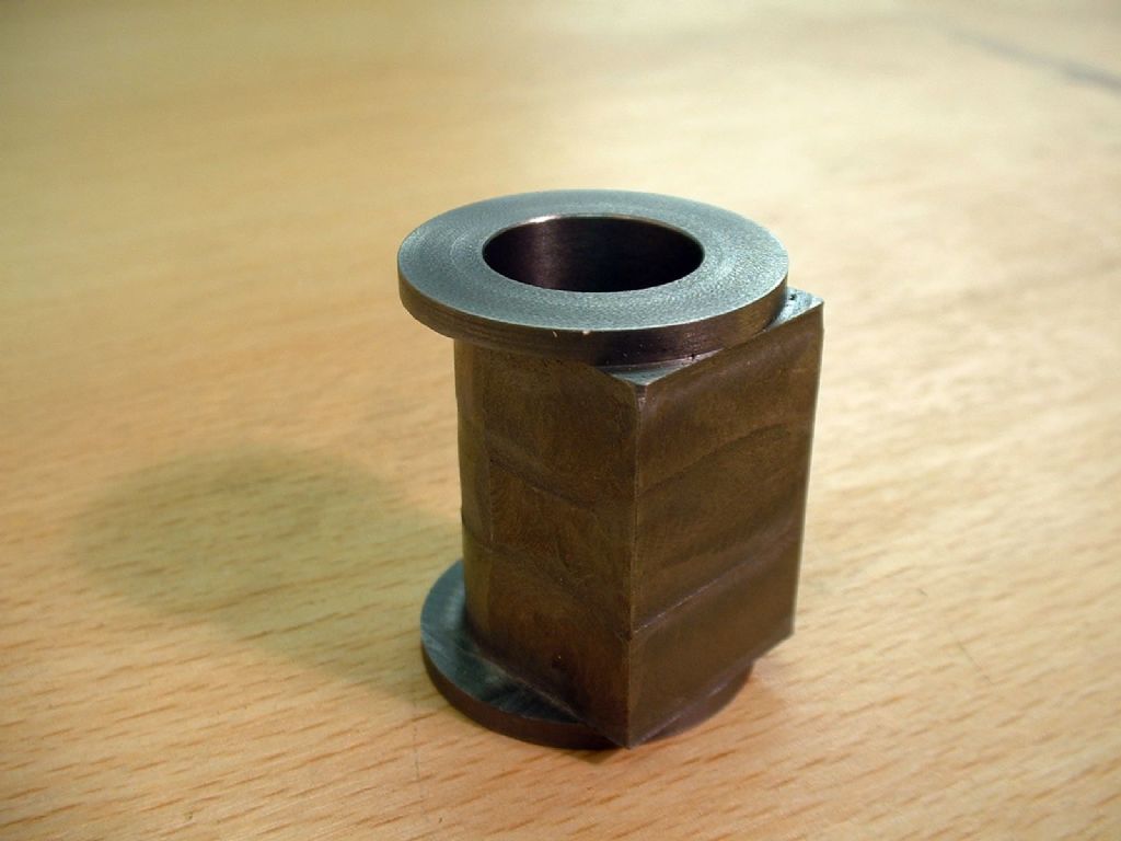 |
| Stub Mandrel | 23/01/2010 20:08:19 |
4318 forum posts 291 photos 1 articles | In theory I could have taken advantage of having the cylinder set concentrically to the bore and carried out other operations before parting it off the cast iron 'stick'. I decided not to do this as at this stage I had still not decided on details like the arrangement of cylinder cover studs, and I could only have drilled one end, anyway. From the sketch it was apparent that external dimensions of the valve chest would be about 3/8" deep and 1"long. The eccentric strap would be about 1/2" diameter. The width of the valve chest could not be deduced directly from the information I had, but the technique used for making the cylinder gave a width of just under 7/8". I had to decide on my own valve dimensions. I decided on steam port width and spacing of 1/16", exhaust port width of 3/32” and port length: 5/16". The ports can be milled out, but for guaranteed accuracy there is nothing to beat a simple ganged cutter as advocated by LBSC. A small diameter cutter is needed, in order to get a reasonable port depth. In this case to get a width of 5/16 and a depth of approximately 1/16" a cutter from 3/8" silver steel was chosen. Using a 1/16" wide parting tool I made a tool blank in the form of three disks on a shank. The end disks being 1/16" wide and the centre disk 3/32". The shank had to be long enough to clear the entire slide face and the top flange. |
| Stub Mandrel | 23/01/2010 20:10:23 |
4318 forum posts 291 photos 1 articles | I milled six teeth on the cutter following a sketch by Edgar Westbury in his M.E. series on ‘Unicorn’. This requires milling very large ‘bites’ with the cutter lined up on the centre line of the blank, in order to create pointed teeth with no top rake, and a very small witness at the tip. With the cutter running fast, but with a slow feed I had no problems with 'grab'. I indexed the blank by eye, as uneven tooth spacing is actually an advantage in this type of cutter, reducing the danger of resonant effects causing chatter. I carefully cleaned up the sides of the teeth with a file. I hardened the whole cutter then tempered it in the oven. I wanted to temper it a bit further than the usual pale straw, as it looked very fragile. I decided to start at gas mark seven (which is supposed to be about 220°/pale straw) knowing the oven thermostat was inaccurate by about one mark. This was just as well, as after a false start (my wife turned off the 'empty' oven), the cutter came out an even pale bronze colour that probably equates to dark straw. I used a diamond slip to clean up the sides of the teeth and to put a shine on the cutting faces. 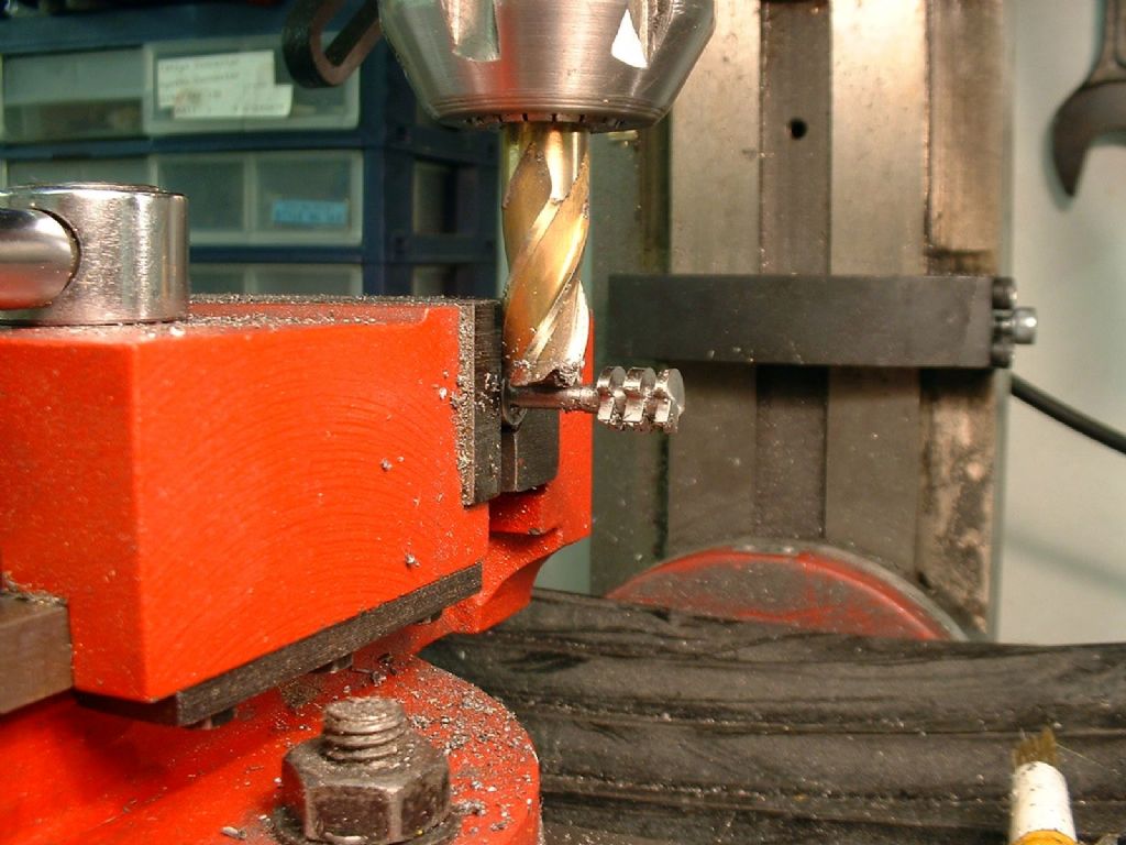 |
| Stub Mandrel | 23/01/2010 20:11:46 |
4318 forum posts 291 photos 1 articles | I clamped the cylinder to the milling table (you could equally clamp it to the vertical slide on a lathe), with the valve face perpendicular to the long axis of the table. I used an edge finder to locate one side of the valve face. This is a 'ball on a stick' which when spinning over a surface stays still, until they are precisely aligned, when it 'runs' along the surface. My ball is meant to be .250", but I miked it at .248”. A difference well worth being aware of if you are going to the bother of using such an aid to setting up! I advanced the cross slide by half the width of the valve face plus half the width of the ball. I now had to fiddle a bit to get the cutter exactly half way up the valve face, ensuring the chuck would clear the fixing bolt. I was very apprehensive that such a delicate looking cutter would bend or break if it dug into the work. With two sets of teeth in the work at once the total cut length would be 7/16", which is an awful lot for a tool shank about 3/16" in diameter. I ran the cutter at about 500 rpm, and fed the work into it very, very slowly. To my satisfaction, the swarf came out more like fine dust than chips, building into a neat cone beside the cylinder. The result was absolutely perfect, far better than I could have achieved with an end mill. It seems like the old guard knew a thing or two. 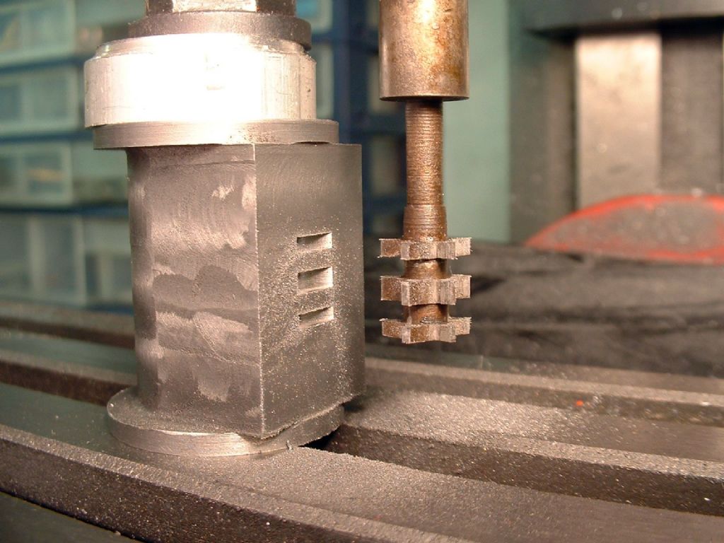 |
| Stub Mandrel | 23/01/2010 20:14:00 |
4318 forum posts 291 photos 1 articles | I used a milling vice to hold the cylinder (protected by aluminium slips) and used a 1/8" FC3 cutter to mill the 3/32" deep recesses at each end of the cylinder. I then used a tilting vice to hold it an angle to drill the steam passages number 53. I marked the position of the upper valve port on the side of the cylinder in pencil, and repeatedly moved the tip of the drill from in the recess to alongside the cylinder to ensure that it would break out into the port without damaging the face. It is essential that the drill neatly enters the corner of the recess for this to be successful. If you feed too fast or the drill is out of line when it starts, it will wander and could either snap, miss the port or, worst of all, emerge in the port face. I used a depth stop on the mill, and as you can see in the photograph, the drill neatly entered one side of the port. Without altering the angle of the vice I inverted the cylinder and drilled the other steam passage. This is a rather nerve-racking procedure. Try to err on the side of drilling at too shallow an angle, as if you miss the port you can ‘poke’ a 1/16" drill into the bottom of each port to link it to he passage. If you use an end mill to create your ports, you can make them a little deeper and the job becomes less critical - you can make a wooden 'cradle' to hold the cylinder for drilling as you won’t need to make small adjustments to the angle. 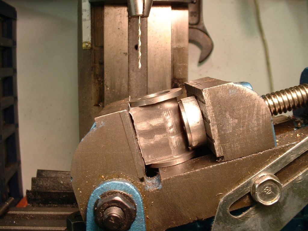 |
| Stub Mandrel | 23/01/2010 20:15:21 |
4318 forum posts 291 photos 1 articles | The final task at this stage was to drill the exhaust port, a less critical operation, as all I had to do is drill parallel to the valve face and avoid breaking into the cylinder bore. The only danger is breaking the drill as it emerges into the port. Now there it is, a cylinder complete, aside from drilling and tapping for the steam chest and end covers. While the process was rather more involved than machining a casting, it was far easier than I expected, largely because of the kind nature of the material used. So, if you decide to model a steam engine for which there are no suitable cylinder castings, have a go at milling one from the solid. 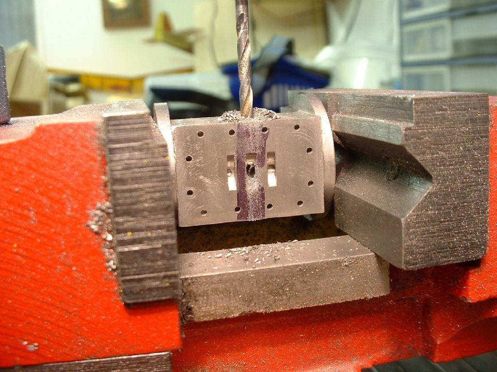 |
| Stub Mandrel | 23/01/2010 20:17:55 |
4318 forum posts 291 photos 1 articles | Epilogue: Just in case you wondered, here is the finished engine. This would also be a good way to machine a pattern for castings. I have made a couple more cylinders, one less than an inch tall - its so neat I'm putting off building it into an engine  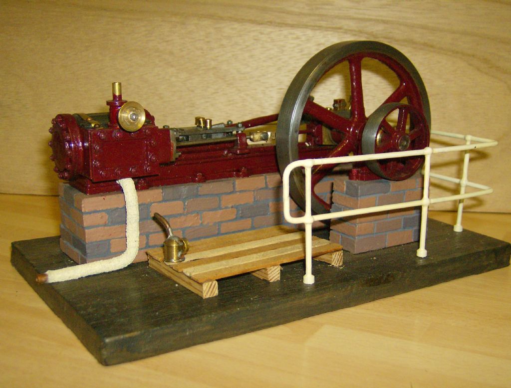 |
| Wolfie | 08/11/2010 12:23:19 |
 502 forum posts | Great tutorial I'm going to try that on my next build! |
| OldMetaller | 08/11/2012 12:59:46 |
 208 forum posts 25 photos | Only just seen this thread- fantastic! Thanks, Stub Mandrel...just got to pluck up the courage to start my own now! Regards, John. |
Please login to post a reply.
Magazine Locator
Want the latest issue of Model Engineer or Model Engineers' Workshop? Use our magazine locator links to find your nearest stockist!
Sign up to our Newsletter
Sign up to our newsletter and get a free digital issue.
You can unsubscribe at anytime. View our privacy policy at www.mortons.co.uk/privacy
Latest Forum Posts
- *Oct 2023: FORUM MIGRATION TIMELINE*
05/10/2023 07:57:11 - Making ER11 collet chuck
05/10/2023 07:56:24 - What did you do today? 2023
05/10/2023 07:25:01 - Orrery
05/10/2023 06:00:41 - Wera hand-tools
05/10/2023 05:47:07 - New member
05/10/2023 04:40:11 - Problems with external pot on at1 vfd
05/10/2023 00:06:32 - Drain plug
04/10/2023 23:36:17 - digi phase converter for 10 machines.....
04/10/2023 23:13:48 - Winter Storage Of Locomotives
04/10/2023 21:02:11 - More Latest Posts...
- View All Topics
Support Our Partners


Shopping Partners
Subscription Offer

Latest "For Sale" Ads
- Reeves** - Rebuilt Royal Scot by Martin Evans
by John Broughton
£300.00 - BRITANNIA 5" GAUGE James Perrier
by Jon Seabright 1
£2,500.00 - Drill Grinder - for restoration
by Nigel Graham 2
£0.00 - WARCO WM18 MILLING MACHINE
by Alex Chudley
£1,200.00 - MYFORD SUPER 7 LATHE
by Alex Chudley
£2,000.00 - More "For Sale" Ads...
Latest "Wanted" Ads
- D1-3 backplate
by Michael Horley
Price Not Specified - fixed steady for a Colchester bantam mark1 800
by George Jervis
Price Not Specified - lbsc pansy
by JACK SIDEBOTHAM
Price Not Specified - Pratt Burnerd multifit chuck key.
by Tim Riome
Price Not Specified - BANDSAW BLADE WELDER
by HUGH
Price Not Specified - More "Wanted" Ads...
Get In Touch!
Do you want to contact the Model Engineer and Model Engineers' Workshop team?
You can contact us by phone, mail or email about the magazines including becoming a contributor, submitting reader's letters or making queries about articles. You can also get in touch about this website, advertising or other general issues.
Click THIS LINK for full contact details.
For subscription issues please see THIS LINK.
Digital Back Issues


Donate

 Register
 Log-in
Model Engineer Magazine
- Percival Marshall
- M.E. History
- LittleLEC
- M.E. Clock

ME Workshop
- An Adcock
- & Shipley
- Horizontal
- Mill

Subscribe Now
- Great savings
- Delivered to your door

Pre-order your copy!
- Delivered to your doorstep!
- Free UK delivery!
All Forum Topics > Stationary engines > Machining a Cylinder from the Solid