Member postings for Andy_G
Here is a list of all the postings Andy_G has made in our forums. Click on a thread name to jump to the thread.
| Thread: Postal Imports ... Notice 143 |
| 01/01/2021 21:40:52 |
What has happened to Michael Gilligan's original posts? (There were several, pointing people to various sections of the document he linked to).
Edited By Andy Gray 3 on 01/01/2021 21:41:50 |
| Thread: TIG is harder than it looks |
| 31/12/2020 17:49:36 |
Posted by Ian McVickers on 30/12/2020 18:40:26:
TIG is harder than it looks. Can't think what you mean...
I'll get there... |
| Thread: Tool identification help please.. |
| 30/12/2020 12:55:10 |
Posted by Tifa 8572 on 30/12/2020 12:51:42:
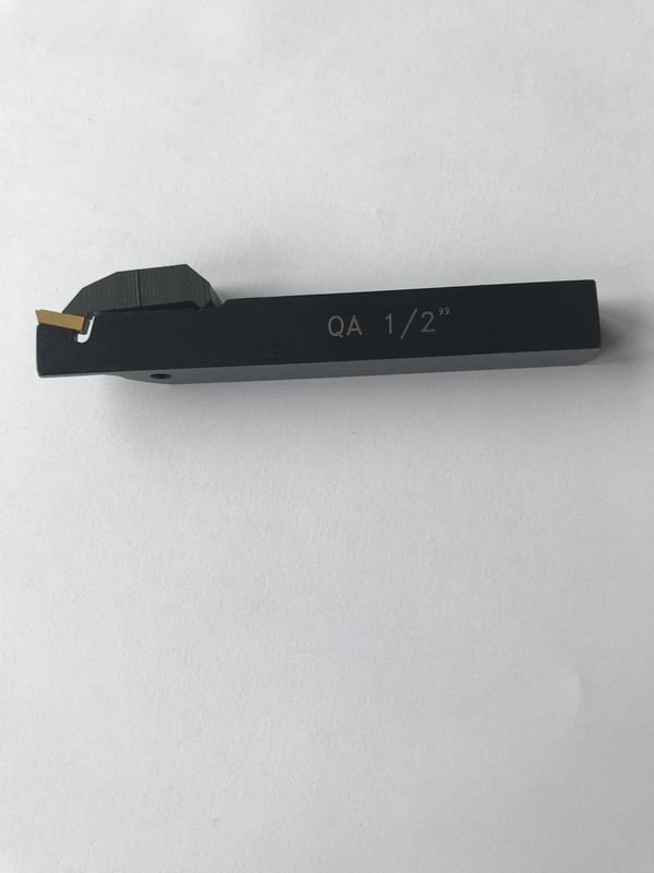
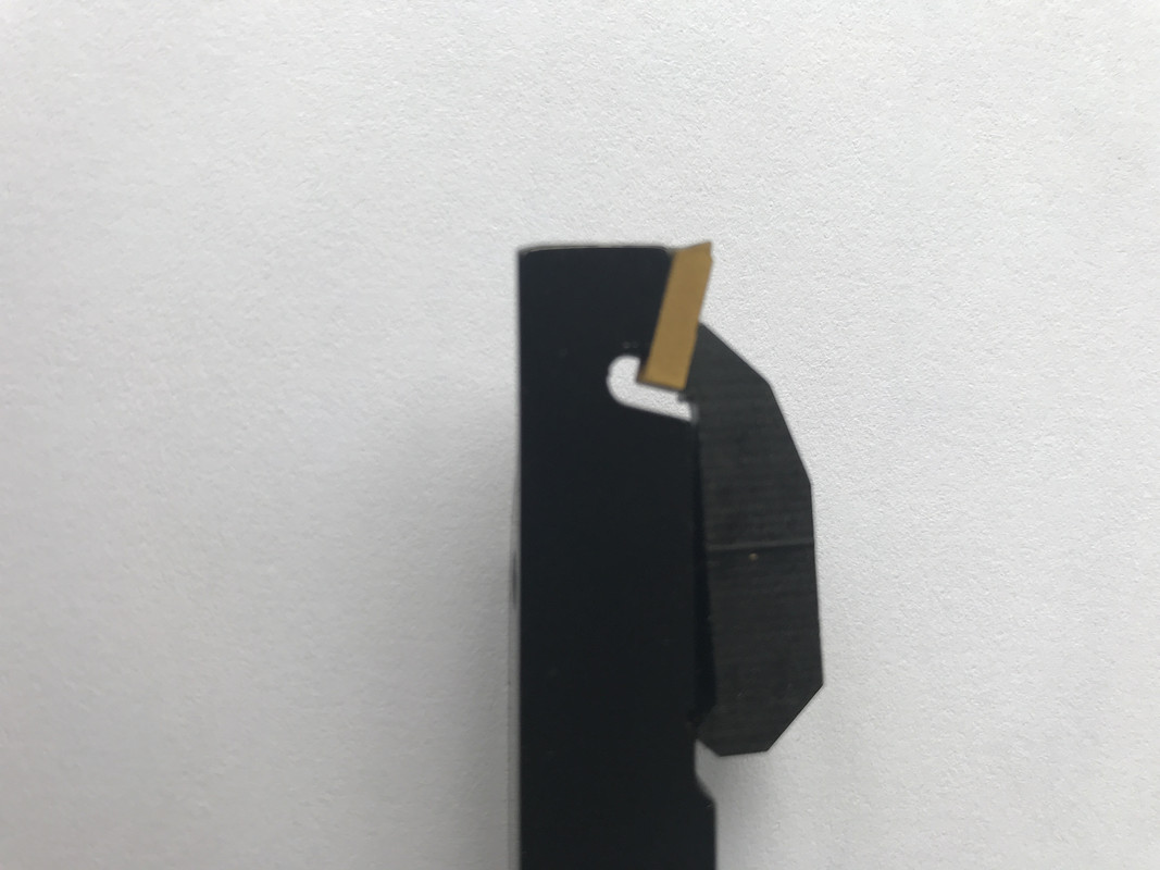
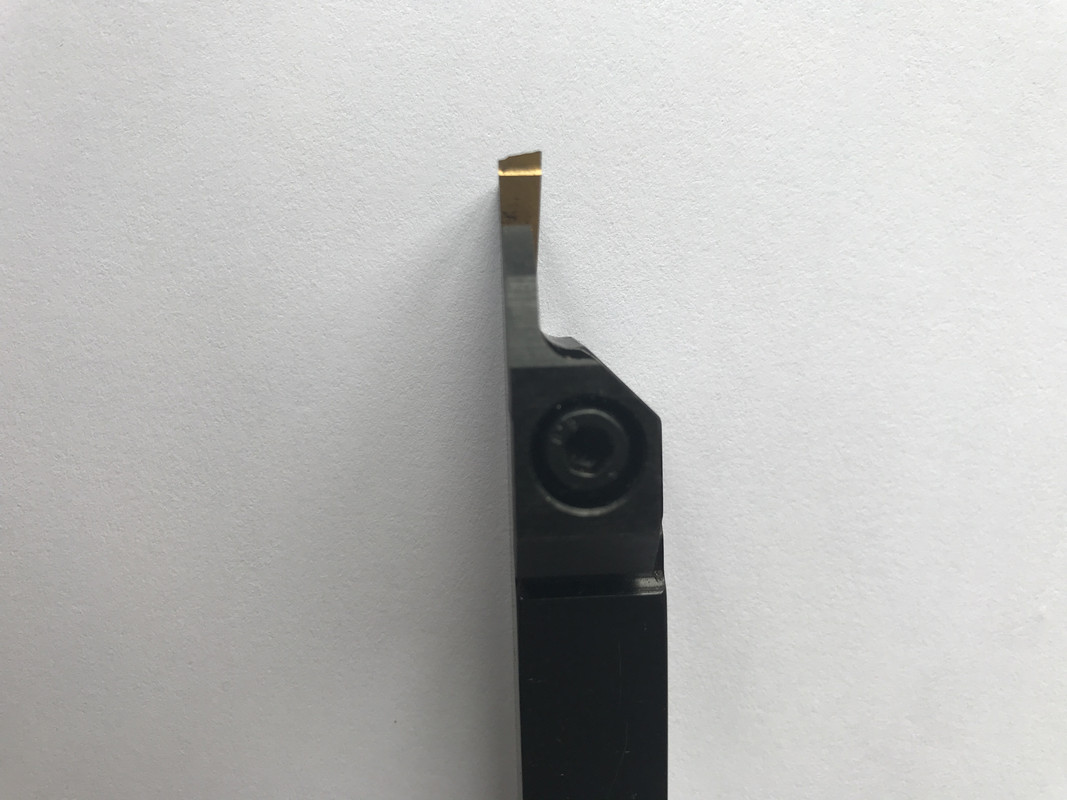
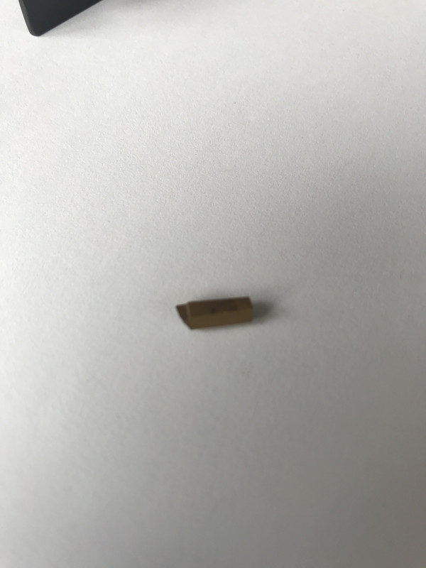
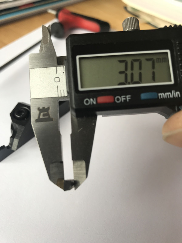
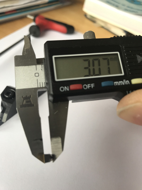
Thank you Andy! Very much appreciated!! No problem - FYI the edit button is in the green banner at the top of the post. If you use the 'direct link' from Post Image (looks like 'https://i.postimg.cc/4Nf9Zg16/IMG-4093.jpg' ) you can paste that into the box that pops up when you click the 'Image' button when composing the message. If it works, you will see the picture as you're writing. Good luck with finding an insert! |
| 30/12/2020 12:48:03 |
Posted by Tifa 8572 on 30/12/2020 12:24:35:
Merry Christmas everybody! Help please....as you can see (hopefully!) I've trashed the end of my cutter. I'd like to order a replacement, but despite searching, I can't find a match. It was bought as part of a set, and original retailers (Chester) say they can only supply a set of inserts for the complete set? Anyone have any idea what this is please? Cheers!
Happy Christmas. |
| Thread: Milling on a mini lathe |
| 28/12/2020 18:28:48 |
Posted by Nick Welburn on 28/12/2020 14:41:30:
Wow - lots of great opinion and thought. My approach is as follows. I’ve ordered this **LINK** and if need be I’ll add a pair of these to the z plate **LINK** If you don't mind me saying, that 'Z' plate setup looks awfully erm... 'springy' - both the bracket itself and the amount of overhang it creates will count against a rigid setup. The carriage lock in the second link is meant for fitting in the rear edge of the saddle, I think. Good luck! |
| 28/12/2020 12:53:00 |
"Myford" style milling slide on a mini lathe:
It works surprisingly well IMHO, within the constraints of the limited cross slide travel and the size of the machine. Details of my adapter plate / boring table for interest (adapt dimensions to suit). It fastens to the compound slide mounts and an additional two holes tapped into the far end of the cross slide. A removable dowel means it can be removed and replaced pretty accurately. (I would knock the dowels out of the vertical slide base and not bother drilling for them if doing it again.) Edit: Looking back at the original question - If one wants to use the vertical slide at an angle to the cross slide, it would probably be necessary to change to mounting location to re-centre the work on account of the limited cross slide travel. Doing away with the dowels in the vertical slide base makes this much easier - one could just drill & tap mounting holes wherever they landed on the adapter plate / boring table.
Edited By Andy Gray 3 on 28/12/2020 13:05:37 |
| Thread: Another newbie question |
| 17/12/2020 19:06:41 |
Posted by John Almond 2 on 17/12/2020 11:24:37:
..., it all seems to move around a bit before the bolt grips then has I tighten the bolt it moves away from me and ends up in that position. any thoughts? It shouldn't move around as you tighten the bolt (a very small amount of movement may be unavoidable). The most obvious thing to check is that there isn't a lump of swarf or dirt stuck between the tailstock and the bed - Slide the tailstock off and clean the bed and mating surfaces carefully. Also check for any damage or 'bruises'. I couldn't see this mentioned above - apologies if I missed it. There's no point performing any alignment until the position is repeatable. |
| Thread: Boat hull formula |
| 08/12/2020 16:34:29 |
Posted by Buffer on 08/12/2020 15:40:22:
Are you sure about that? Fair cop. Didn’t want to get into righting moments, but simplified it a step too far Point should have been that stability is a consideration as well as just displacement which requires consideration of the C of G. Must try harder! |
| 08/12/2020 13:02:46 |
Posted by SillyOldDuffer on 08/12/2020 10:52:52
provided the total weight of the model is smaller than the displacement, it will float.
It won’t float for long unless the centre of gravity is also below the centre of buoyancy (lateral and transverse) I’d be surprised if the displacement didn’t come out between 7 & 8 kg (15-18 lbs). Anyone remember the ‘Krispie’? 36” long sailing boat built from strips of cereal packet (I built one once...). |
| 07/12/2020 21:35:10 |
Posted by SillyOldDuffer on 07/12/2020 21:12:35: , ¹⁄₁₆" balsa is lighter than 16swg copper. But the copper is stronger, potentially making it possible to reduce frames, keel and machinery supports. I'll do the sums later - weight of a 16swg copper box will indicate if it's a big problem or not. Specific strength (strength to weight ratio) - Higher is better: Balsa is 521 (kNm/kg) Copper is 24.7 (kNm/kg) For reference, carbon / epoxy composite 785 (kNm/kg) (Ref) So if everything was built to the same strength, a copper hull would be ~21 times heavier than balsa wood, a carbon fibre / epoxy one would be 50% lighter. Regarding the business about calculating volume - the block coefficient gives the ratio between the volume (and displacement).of a hull as a fraction of the rectangular bounding box of the underwater dimensions. There are many references on line where one can find typical block coefficient values for different hull forms which can be applied to the model dimensions to give a idea of displacement - as already pointed out, it's best to have something in reserve for trimming & stability. |
| 07/12/2020 11:26:41 |
Look up ‘prismatic coefficient’ and ‘block coefficient’ - they won’t give you the answer, but should help estimating displacement. From a quick look, tug hulls typically have a block coefficient of 0.6, so will displace 60% of the theoretical length x beam x draught volume.
|
| Thread: Suggestions for lathe-only projects? |
| 03/12/2020 19:32:26 |
Posted by William Ayerst on 03/12/2020 18:44:53:
What's the diameter of the lugs please? That photo was from your link to show the slide, so I'm not sure about those. On the one I recently acquired (Chinese / Indian / WHY copy) the dowels are 3/8" diameter. (But I don't have T slots for them to fit into!). |
| 03/12/2020 17:54:53 |
Posted by William Ayerst on 01/12/2020 20:21:09:
... but to swivel like that you have to loosen the bolt, which means the whole slide slops around in the t-slot. This design (not this vice): https://www.nielsmachines.com/en/myford-accessories.html Does yours not have the dowel pins that fit into the T slot to stop the base rotating?
|
| Thread: Model tug boat plans |
| 29/11/2020 11:41:15 |
Posted by BOB BLACKSHAW on 29/11/2020 11:18:19:
how do you convert the drawing profile to the full size, In the olden days (when I used to make model boats) I would transfer the lines onto graph paper by tracing or carbon paper then scale that by hand to whatever size I needed (drawing out a custom grid if it wasn't a straightforward multiple). The full lines got transferred to templates using more carbon paper. These days, you could probably do it all with a photocopier. |
| Thread: Suggestions for lathe-only projects? |
| 28/11/2020 21:17:55 |
Thank you Posted by William Ayerst on 28/11/2020 20:59:10:
I assume best to use the 3-jaw for milling and the jacobs chuck for drilling, in the headstock? With a little bit more expenditure you could get a finger collet to hold milling cutters in the headstock spindle (you would need to make a drawbar - e.g. a long bolt + collar), I guess a 6mm and/or a 10mm collet (<£10 each) could cover quite a range of milling cutters. FWIW, In the limited amount of milling I have done on my lathe (not Myford) I find the cutters run more smoothly in a collet than in a chuck and it's easier to see what you're doing. |
| 28/11/2020 18:17:25 |
I'd honestly buy a cheap pillar drill before the milling slide. This was made just using a lathe and a cheap pillar drill. I could have done without the pillar drill, but wouldn't want to. (Apologies for blowing my own trumpet, but one can make an awful lot of things on a lathe, and many, many people have - one is only limited by one's imagination.)
(OK, I bought the gears and the sparkplug!)
Edited By Andy Gray 3 on 28/11/2020 18:21:27 Edited By Andy Gray 3 on 28/11/2020 18:22:32 Edited By Andy Gray 3 on 28/11/2020 18:24:41 |
| Thread: Bearing identification |
| 27/11/2020 14:18:07 |
Posted by Kiwi Bloke on 27/11/2020 10:27:39:
I still want to know what the difference is - if any! The 99502H seems to have imperial ID & OD, but metric width: This lists both (pdf file) 99502H ID 0.6250" / 15.875mm OD 1.375" / 34.925mm Width 0.4331" / 11mm 1623 ID 0.6250" OD 1.375" Width 0.4375" (7/16" ) = (11.113 mm) Edited By Andy Gray 3 on 27/11/2020 14:18:53 |
| Thread: Another engineering masterclass |
| 25/11/2020 20:49:57 |
Funnily enough, this just popped up elsewhere: (I'm a fan, in case you hadn't realised!
 ) ) |
| 25/11/2020 17:22:25 |
Posted by John MC on 25/11/2020 07:24:51:
The way I look at these is would they stand up to "real world" use, They do seem to. I particularly admire the fact that he creates useable vehicles rather than 'engineering sculptures' what would fall to pieces if started. Here's his little 4 cylinder 350 being revved to 7k RPM and hustled around some bends (towards the end of the video) Here he's riding his V10 Dodge Viper engined bike (In part 2). He reckons to have put over 9000 miles on it since it was built. Part 1:
Part 2: I find it frankly astonishing that anything so monstrous could be engineered to be usable. The fact that he's prepared to rest his nuts on it and open the throttle to hit 200mph also speaks of man who is confident in his engineering ability. He also claims to have over 9k miles on the Pratt & Whitney 5 litre V twin Part 1: Part 2: Edited By Andy Gray 3 on 25/11/2020 17:23:41 |
| Thread: Unimat 3 motor diode |
| 23/11/2020 22:36:11 |
Looks like a DS 1.8 16A general purpose rectifier - 1.7A If / 1600V PIV https://www.web-bcs.com/diode/dc/da/DS1,8-16A.php?lan=en&cl=1
(Possibly used to half-wave rectify the incoming mains to give reduced speed, based on your description, but I have no knowledge of the Unimat circuit). |


Magazine Locator
Want the latest issue of Model Engineer or Model Engineers' Workshop? Use our magazine locator links to find your nearest stockist!
Sign up to our Newsletter
Sign up to our newsletter and get a free digital issue.
You can unsubscribe at anytime. View our privacy policy at www.mortons.co.uk/privacy
Latest Forum Posts
- *Oct 2023: FORUM MIGRATION TIMELINE*
05/10/2023 07:57:11 - Making ER11 collet chuck
05/10/2023 07:56:24 - What did you do today? 2023
05/10/2023 07:25:01 - Orrery
05/10/2023 06:00:41 - Wera hand-tools
05/10/2023 05:47:07 - New member
05/10/2023 04:40:11 - Problems with external pot on at1 vfd
05/10/2023 00:06:32 - Drain plug
04/10/2023 23:36:17 - digi phase converter for 10 machines.....
04/10/2023 23:13:48 - Winter Storage Of Locomotives
04/10/2023 21:02:11 - More Latest Posts...
- View All Topics
Support Our Partners


Shopping Partners
Subscription Offer

Latest "For Sale" Ads
- Reeves** - Rebuilt Royal Scot by Martin Evans
by John Broughton
£300.00 - BRITANNIA 5" GAUGE James Perrier
by Jon Seabright 1
£2,500.00 - Drill Grinder - for restoration
by Nigel Graham 2
£0.00 - WARCO WM18 MILLING MACHINE
by Alex Chudley
£1,200.00 - MYFORD SUPER 7 LATHE
by Alex Chudley
£2,000.00 - More "For Sale" Ads...
Latest "Wanted" Ads
- D1-3 backplate
by Michael Horley
Price Not Specified - fixed steady for a Colchester bantam mark1 800
by George Jervis
Price Not Specified - lbsc pansy
by JACK SIDEBOTHAM
Price Not Specified - Pratt Burnerd multifit chuck key.
by Tim Riome
Price Not Specified - BANDSAW BLADE WELDER
by HUGH
Price Not Specified - More "Wanted" Ads...
Get In Touch!
Do you want to contact the Model Engineer and Model Engineers' Workshop team?
You can contact us by phone, mail or email about the magazines including becoming a contributor, submitting reader's letters or making queries about articles. You can also get in touch about this website, advertising or other general issues.
Click THIS LINK for full contact details.
For subscription issues please see THIS LINK.
Digital Back Issues


Donate

 Register
 Log-in
Model Engineer Magazine
- Percival Marshall
- M.E. History
- LittleLEC
- M.E. Clock

ME Workshop
- An Adcock
- & Shipley
- Horizontal
- Mill

Subscribe Now
- Great savings
- Delivered to your door

Pre-order your copy!
- Delivered to your doorstep!
- Free UK delivery!