Member postings for John Baron
Here is a list of all the postings John Baron has made in our forums. Click on a thread name to jump to the thread.
| Thread: That little elf under the workbench again |
| 21/03/2021 18:55:26 |
Posted by Bill Dawes on 21/03/2021 18:31:38:
Well a happy ending for me but before that a disaster, had another go with the magnet on a telescopic stick and lost the end under my milling machine!! Good news, I found my 6BA socket, it had bounced up and was nestling in some old shirts under a bench I had stored ready for turning into wipers. Bill D. You need a bigger magnet
|
| Thread: Broken Electric motor Junction box |
| 21/03/2021 18:53:28 |
Posted by Oily Rag on 21/03/2021 16:24:57:
Good afternoon all, Just had an accident in the workshop that has damaged the Brook Crompton 0.37kW electric motor on my Atlas 7" shaper. A heavy bar slipped and crashed down on the motor's junction box (fortunately the shaper was being moved and was not plugged in to the mains! ) the result is the whole of the junction box has disintegrated with only two parts of any reasonable size. Does anyone know where a junction box to suit can be obtained from? Motor ref number is HPA 534 TFBH 3A Pictures of the damage, I guess the orientation is going to be skew-whiff, appreciate it if a mod could rotate accordingly.
Thanks in anticipation, Martin Hi Martin, You have all the motor info, why not just call Brooks and get a new original one ! http://brookcrompton.com/distributors.aspx
|
| Thread: 1" Die Stock |
| 20/03/2021 15:12:12 |
Hi Guys, Thanks for your posts ! Nobody pointed out that I had forgotten to do the drawing of the fastening/adjusting screw holes and positions
Edited By John Baron on 20/03/2021 15:14:05 Edited By John Baron on 20/03/2021 15:14:32 Edited By John Baron on 20/03/2021 15:14:48 |
| 17/03/2021 17:59:26 |
Hi Guys, I managed to strip the thread in my cheap Chinese die stock recently, so I decided to make a new one. I did a drawing to give me something to follow with my new DRO on the mill. I've placed a copy here.
The bits in blue are just in case somebody would like to make one with the corners milled off. The 7 mm holes are for threading M8 for handles to screw into. My existing handles are threaded M8.
|
| Thread: Motor control board |
| 13/03/2021 19:47:14 |
Posted by Keith Matheson on 13/03/2021 18:28:44:
Hi The OP here. I’m sure we all love a happy ending and some resolution ( and a thread that comes to a satisfactory ending!) Well I put the new brushes in and Ta Daaaahh! She works again Hi Keith, Your motor may not be identical to mine. The brushes in mine are 3.6 by 10 mm and 15 mm long. I had similar problems getting hold of some brushes, so I made my own. If you measure the brass sleeve that will tell you the size. As far as the semiconductors on the power board are concerned, failed diodes almost invariably go short circuit, the more likely things to fail are the SCR's. If its any help I'm near York.
Edited By John Baron on 13/03/2021 19:49:36 |
| Thread: Two or three axis DRO |
| 12/03/2021 07:41:42 |
Hi Guys, I've just fitted a DRO to my Chinese copy of an Optimum mill. I put a glass scale on the column so that I can read the head height. My mill also has a readout on the quill for drilling depth.
I used a pair of aluminium brackets to mount the scale. I also used a spacer plate between the read head and mill head to match the thickness of the brackets.
I think the protective plastic dust cover is a nice touch ! Keeps greasy fingers off the membrane buttons.
Like all things, I should have got one years ago...
|
| Thread: ML7 Topslide Angle Limitations |
| 12/03/2021 07:25:42 |
Posted by John Barber 5 on 11/03/2021 23:49:06:
I'm a relatively new ML7 user, and this evening I realised for the first time that the top-slide clamping arrangement doesn't give you the full range of angles. It can't come within 30 degrees or so of being perpendicular to the lathe axis, as would be required for turning a blunt taper. This must mean that there are certain turned components which it is impossible to make on an ML7 - a truly shocking thought! Or am I missing something? That is why they changed it on the S7 so that it rotates through a full 360 degrees. On the S7 it is secured by two screws, one on each side of the cross slide.
|
| Thread: Bandsaw overhang |
| 11/03/2021 10:24:01 |
Posted by Peter Ellis 5 on 10/03/2021 22:17:49:
I have a shortish 75mm bar I need a slice off. I am minded to bolt it to something that the vice can hold better. What would you do ?
Hi Peter, Guys, When I refurbished mine I made a blocking piece to fill that gap ! The short end cannot now disappear through the gap and the material is supported right to the end. However beware that very thin pieces may get dragged into the gap between the blade and guide, jamming the blade.
Before !
After !
No more lost or unsupported pieces.
|
| Thread: Motor control board |
| 10/03/2021 09:03:46 |
Posted by Michael Gilligan on 10/03/2021 08:45:25:
Posted by John Baron on 10/03/2021 07:41:44:
[…] The theory and the math is there on the Internet !
. Ah but ... this is on the Internet ! MichaelG. True !
|
| 10/03/2021 07:41:44 |
Hi Andrew, Guys, The Device known as a voltage-dependent resistor (VDR), is not a resistor at all It is a semiconductor device more akin to a voltage sensitive diode. A similar mechanism as a Zenner diode but it has the same electrical characteristics for current in both directions. In other words it is not unidirectional as a diode is but Bidirectional. FWIW a resistor is a linear device. The behaviour is according to Ohms Law.
As far as discussing motor brushes is concerned, I've better things to do than going round in ever decreasing circles ! The theory and the math is there on the Internet !
|
| 09/03/2021 19:42:39 |
Hi Malcolm, Guys, Resistivity "resistance" is a constant ! It does not vary with voltage. There are however resistive devices that increase or decrease in resistance with temperature. For any given resistance the current through it will increase with voltage. I do agree that the current drawn by a motor tends to increase as the motor load increases. Motor brushes are very low resistance devices, fractions of an Ohm in most cases, loading them with copper increases the hardness of the brush, in turn improving the wear resistance, usually at the expense of the copper segments of the commutator. Actually the arcing that one often gets at the brush/commutator interface can wear the brush as much as just the friction between them. But as you imply quite a complex subject, much of which has been alleviated with the advent of brushless DC motors.
|
| 09/03/2021 14:51:07 |
Posted by Macolm on 09/03/2021 10:30:35:
The brush material resistivity is mainly a function of the supply voltage. No it isn't ! In fact it has absolutely nothing to do with voltage. Material resistivity is a function of the material ! It is a measurement of conductivity, the ability to conduct electricity.
Edited By John Baron on 09/03/2021 14:54:09 |
| Thread: T slots |
| 09/03/2021 07:26:42 |
Hi Stevei, Very nice protectors for the mill table ! I'm just about to make some new ones for mine ! I've just fitted a set of scales for the DRO on mine and am doing some servicing whilst I'm at it. Surprising what you find when you start stripping a Chinese mill to bits. I'm about to investigate sorting out the quill bearings ! They feel fine in the machine, but quite lumpy with the quill out and turned by hand.
Edited By John Baron on 09/03/2021 07:28:48 |
| Thread: Motor control board |
| 09/03/2021 07:16:54 |
Posted by Keith Matheson on 08/03/2021 21:15:20:
Thanks for all the suggestions and guidance so far. Gratefully received. It makes problem solving soooooooo much easier and less time consuming - and hopefully less expensive. Anyway, onto current matters. I took the brushes out of the motor and found one broken in two (with the associated wire unattached) and the second looking somewhat short. I have found the same cross sectional area brushes on evil bay so have ordered a pair. I will report back what happens (I do so much hate a thread that doesn’t reach some sort of resolution)! I will also pop the new diodes into the previously died board and see if I now have a spare. Thanks again. keith MM ps like the idea of a pc fan attached to the motor housing- will do this as a sensible addition. Hi Keith, Guys, Thanks for the picture, that is what I expected to see ! just curious, did you measure the dimensions of yours ? I wonder weather they are the same size. As far as the brush hardness is concerned there is no difference between AC and DC brushes, as seen in universal motor use. There are however quite marked different grades and composition of brushes intended for different applications. For instance, some brushes are copper loaded and some are very soft, like the carbon material that I am using for making my replacements. I'm not saying that the stuff I'm using is correct, but it works for me. The wear on the brush is basically due to two causes, brush pressure and arcing. Higher pressure on the brush reduces arcing but increases wear hence the reason for harder brush material. I would remove the brush cap and inspect the commutator for wear and blow out any dust. Inspect the wiring to the brush holders for any heating damage, particularly loose push on fix connectors. Any looseness will cause heating leading to failure of the insulation of the brush holder. DO NOT attempt to remove the armature ! Apart from the fact that it will be very difficult, it will cause the field magnets to loose their strength. HTH.
|
| Thread: Home Made Rear Toolpost Issue |
| 07/03/2021 22:04:35 |
Hi Dr_GMJN, Guys, You could make a holder for the blade that clamps into the slot in the tool block and use shims under it ! There is no way I would want to start shimming under the whole tool post.
|
| Thread: Motor control board |
| 07/03/2021 21:59:51 |
Hi Keith, Good question ! Those big brushes were given to me by a motor re-winders in Sheffield quite a while ago. They came out of their scrap bin. I haven't a clue what they would have belonged to, but they are enormous compared to the ones that I make from them.
The one on the right is the one that I've made, it also requires cutting in half. That big brush is 50 mm by 32 mm by 6 mm thick. Manufactured by Morganite I believe. The brushes in the mill motor are 3.6 mm thick by 10 mm wide and 15 mm long. Everybody I've tried for replacements wants to sell me an expensive motor costing an arm and a leg !
|
| 07/03/2021 21:47:53 |
Posted by noel shelley on 07/03/2021 21:04:38:
No little copper wire down the middle of the spring to carry the load ? It might be worth wipping the mosfets or switching devices of the heat sink and checking them. Nothing ventured nothing gained ? Noel Hi Noel, Guys, No ! The little pigtails don't exist on my home brew brushes, they did on the originals, but they simply fell out allowing the motor current to destroy the springs.
|
| Thread: Home Made Rear Toolpost Issue |
| 07/03/2021 21:25:41 |
Posted by Dr_GMJN on 07/03/2021 21:09:16:
Ok thanks all. One way or another I'll retrieve it form the bin and give it one last go. Slot or top plate is the question. Top plate winning so far. I think I've got some plate that will do. I think anything 3/8" inch or thicker will be quite satisfactory. Don't forget that the nut on top will also be adding to the security of the plate. For what its worth, and I'm sure you have seen the picture of mine, I use a cheap Chinese parting blade that is 2 mm thick, 12 mm wide and 200 mm long. It is perfectly rectangular in section. And is clamped by two screws with a third used to clamp the supporting piece. I don't have any packings or shims under the blade, the height of the whole tool block being used to set the blade centre height.
|
| 07/03/2021 21:00:14 |
Hi Dr_GMJN, Just putting a steel plate on to replace the broken lip will not change the tool height or be any weaker than it would have been had it not failed. You could of course do a much better job which would require far more work for very little benefit ! What I've and I noticed other suggested the same would produce a quick and easy fix. Lets see piece of plate, five holes to drill four holes to tap. Two M8 two M6. Saw the top off, mill it clean, mark out for the five holes, drill. Tap the M6 holes, spot through the M8 ones. Drill 7 mm, thread the block M8. Fit the plate. Job done ! Opps forgot the hole for the long clamp screw.
Edited By John Baron on 07/03/2021 21:02:25 |
| 07/03/2021 20:37:55 |
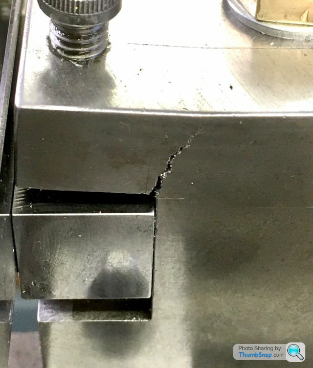
Posted by Dr_GMJN on 07/03/2021 18:06:11:
So I milled the key to clear the new bolt: Don't mess about ! Just break that lip off, mill a flat across the top and bolt a steel plate on there to replace the broken bit. That failure is about what you would expect from cast iron. Use a pair of M8 coarse threaded bolts. to fasten the new plate. Shouldn't take more than an hour !
Edited By John Baron on 07/03/2021 20:39:11 |
![img_3705[1].jpg](/sites/7/images/member_albums/58814/891152.jpg "img_3705[1].jpg")
![img_3706[1].jpg](/sites/7/images/member_albums/58814/891153.jpg "img_3706[1].jpg")
![img_3707[1].jpg](/sites/7/images/member_albums/58814/891154.jpg "img_3707[1].jpg")


 . Thanks for the advice and the useful comments. As I kept the old dead board from before I will swap over the diodes I ordered and see if I now have a spare- that would be a result. The only odd thing was that the slot that the original bushes (and the like for like replacements) went in was enormous when compared to the bushes. I would say easily 2mm all the way around. Is this normal or did the motor factory run out of the correct bushes and just whacked in any thing that would work to get it out of the door? Chinese quality assurance? You are assured it is a low price? Best regards Keith MM


Magazine Locator
Want the latest issue of Model Engineer or Model Engineers' Workshop? Use our magazine locator links to find your nearest stockist!
Sign up to our Newsletter
Sign up to our newsletter and get a free digital issue.
You can unsubscribe at anytime. View our privacy policy at www.mortons.co.uk/privacy
Latest Forum Posts
- *Oct 2023: FORUM MIGRATION TIMELINE*
05/10/2023 07:57:11 - Making ER11 collet chuck
05/10/2023 07:56:24 - What did you do today? 2023
05/10/2023 07:25:01 - Orrery
05/10/2023 06:00:41 - Wera hand-tools
05/10/2023 05:47:07 - New member
05/10/2023 04:40:11 - Problems with external pot on at1 vfd
05/10/2023 00:06:32 - Drain plug
04/10/2023 23:36:17 - digi phase converter for 10 machines.....
04/10/2023 23:13:48 - Winter Storage Of Locomotives
04/10/2023 21:02:11 - More Latest Posts...
- View All Topics
Support Our Partners


Shopping Partners
Subscription Offer

Latest "For Sale" Ads
- Reeves** - Rebuilt Royal Scot by Martin Evans
by John Broughton
£300.00 - BRITANNIA 5" GAUGE James Perrier
by Jon Seabright 1
£2,500.00 - Drill Grinder - for restoration
by Nigel Graham 2
£0.00 - WARCO WM18 MILLING MACHINE
by Alex Chudley
£1,200.00 - MYFORD SUPER 7 LATHE
by Alex Chudley
£2,000.00 - More "For Sale" Ads...
Latest "Wanted" Ads
- D1-3 backplate
by Michael Horley
Price Not Specified - fixed steady for a Colchester bantam mark1 800
by George Jervis
Price Not Specified - lbsc pansy
by JACK SIDEBOTHAM
Price Not Specified - Pratt Burnerd multifit chuck key.
by Tim Riome
Price Not Specified - BANDSAW BLADE WELDER
by HUGH
Price Not Specified - More "Wanted" Ads...
Get In Touch!
Do you want to contact the Model Engineer and Model Engineers' Workshop team?
You can contact us by phone, mail or email about the magazines including becoming a contributor, submitting reader's letters or making queries about articles. You can also get in touch about this website, advertising or other general issues.
Click THIS LINK for full contact details.
For subscription issues please see THIS LINK.
Digital Back Issues


Donate

 Register
 Log-in
Model Engineer Magazine
- Percival Marshall
- M.E. History
- LittleLEC
- M.E. Clock

ME Workshop
- An Adcock
- & Shipley
- Horizontal
- Mill

Subscribe Now
- Great savings
- Delivered to your door

Pre-order your copy!
- Delivered to your doorstep!
- Free UK delivery!