Forum sponsored by:

Stuart S50
| Mike Bondarczuk | 02/04/2014 17:33:57 |
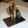
| 91 forum posts 6 photos | Hi to all, Embarking on a Stuart S50 build and armed only with enthusiasm, an ML7 and a small mill and a huge gap in knowledge, so here is no doubt the first of many questions. I am following Tubal Cains "Sally" build guides as in Model Engineer 1992 and have a question about the location of the three holes on the bedplate for the cylinder. I have followed his instructions and find that these holes appear to be too far to the right of the bedplate, so am asking whether his dimension of 5 7/16" from the centre of the axle to the middle hole location is correct. I am attaching a photo in which it is possible to see the scribe marks for the three holes and the furthest to the right just does not seem right. How critical is this 5 7/16" and is the eventual distance between the piston travel and the axle a fixed distance or can to be varied to suit the casting. Any suggestions are most welcome. With thanks, Mike
|
| Dismaldunc | 02/04/2014 21:27:34 |
| 91 forum posts 8 photos | Hi Mike Sent you a PM
Dunc |
| thomas oliver 2 | 04/04/2014 23:45:03 |
| 110 forum posts | I have an S50 assembled from a Stuart Turner kit and have checked the dimension which does appear to be 5 7/16ins. I also have a part complete one marked out and the marking appears exactly as yours. It would appear that the bosses are not too well positioned. |
| GaryM | 06/04/2014 11:30:25 |
 314 forum posts 44 photos | Hi Mike, I thought the same as you, that they didn't line up with the pads very well. If you haven't drilled it already, here is what I did. I left the hole nearest the crank in the same location, moved the second hole (valve side) 1/16" nearer to the crank and moved the third hole (farthest from crank) 1/8" nearer to the crank. So that would make the 5 7/16" dimension to the centre hole 5 3/8" and the other two holes 7/16" from that rather than 1/2". Pics below, you can just see the original scribe marks. Having said all that I've not got it running yet due to "essential" decorating of hall, stairs and landing. Hope this helps. Gary
|
| Anthony | 06/04/2014 13:28:33 |
| 6 forum posts 3 photos | I built an S50 from castings and did the same as GaryM. I also put small pins in on the base pads at the sides of the bolt holes as suggested by Tubal Cain. This really does help later on in the build, as the cylinder is always held in the correct position whilst the bolts are tightened up. Good luck with your build. |
| Mike Bondarczuk | 06/04/2014 15:20:38 |
| 91 forum posts 6 photos | Hi Gary, Anthony and everyone else who offered advice, Many thanks for the valuable information and as of yet I have not drilled any holes but with your advice now know what to do. Will post more pics as I get to grips with the final marking out again. With thanks, Mike |
| Michael Edwards 1 | 01/01/2019 16:34:23 |
 59 forum posts 46 photos |
Regards Mike Edited By Michael Edwards 1 on 01/01/2019 16:35:45 Edited By Michael Edwards 1 on 01/01/2019 16:36:22 Edited By Michael Edwards 1 on 01/01/2019 16:36:41 |
| JasonB | 01/01/2019 16:49:41 |
 25215 forum posts 3105 photos 1 articles | I would set the cross head guides to run as straight (Vertical in photo) as possible and then find the ctr line between the two of them. From that you have the ctr of the cylinder so can set out it's mounting holes. Set the sides of the bearings from this ctr line too but if you can't get things to fit then the far left is not critical and if the the right side does not work out then adjust the crank web width to suit. |
| Michael Edwards 1 | 01/01/2019 17:11:40 |
59 forum posts 46 photos | Thank you Jason.Will crack on with that now. Regards Mike |


Please login to post a reply.
Magazine Locator
Want the latest issue of Model Engineer or Model Engineers' Workshop? Use our magazine locator links to find your nearest stockist!
Sign up to our Newsletter
Sign up to our newsletter and get a free digital issue.
You can unsubscribe at anytime. View our privacy policy at www.mortons.co.uk/privacy
Latest Forum Posts
- *Oct 2023: FORUM MIGRATION TIMELINE*
05/10/2023 07:57:11 - Making ER11 collet chuck
05/10/2023 07:56:24 - What did you do today? 2023
05/10/2023 07:25:01 - Orrery
05/10/2023 06:00:41 - Wera hand-tools
05/10/2023 05:47:07 - New member
05/10/2023 04:40:11 - Problems with external pot on at1 vfd
05/10/2023 00:06:32 - Drain plug
04/10/2023 23:36:17 - digi phase converter for 10 machines.....
04/10/2023 23:13:48 - Winter Storage Of Locomotives
04/10/2023 21:02:11 - More Latest Posts...
- View All Topics
Support Our Partners


Shopping Partners
Subscription Offer

Latest "For Sale" Ads
- Reeves** - Rebuilt Royal Scot by Martin Evans
by John Broughton
£300.00 - BRITANNIA 5" GAUGE James Perrier
by Jon Seabright 1
£2,500.00 - Drill Grinder - for restoration
by Nigel Graham 2
£0.00 - WARCO WM18 MILLING MACHINE
by Alex Chudley
£1,200.00 - MYFORD SUPER 7 LATHE
by Alex Chudley
£2,000.00 - More "For Sale" Ads...
Latest "Wanted" Ads
- D1-3 backplate
by Michael Horley
Price Not Specified - fixed steady for a Colchester bantam mark1 800
by George Jervis
Price Not Specified - lbsc pansy
by JACK SIDEBOTHAM
Price Not Specified - Pratt Burnerd multifit chuck key.
by Tim Riome
Price Not Specified - BANDSAW BLADE WELDER
by HUGH
Price Not Specified - More "Wanted" Ads...
Get In Touch!
Do you want to contact the Model Engineer and Model Engineers' Workshop team?
You can contact us by phone, mail or email about the magazines including becoming a contributor, submitting reader's letters or making queries about articles. You can also get in touch about this website, advertising or other general issues.
Click THIS LINK for full contact details.
For subscription issues please see THIS LINK.
Digital Back Issues


Donate

 Register
 Log-in
Model Engineer Magazine
- Percival Marshall
- M.E. History
- LittleLEC
- M.E. Clock

ME Workshop
- An Adcock
- & Shipley
- Horizontal
- Mill

Subscribe Now
- Great savings
- Delivered to your door

Pre-order your copy!
- Delivered to your doorstep!
- Free UK delivery!
All Forum Topics > Beginners questions > Stuart S50