Forum sponsored by:

3" Burrell build
Fitting the water pump
| Deric | 18/01/2014 14:45:45 |
| 44 forum posts 27 photos | Is anyone building or has built the 3" Burrell to the Plastow design? My brother and I have been building this engine for the last year and up until now I/we have managed ok and made it up where there were no dimensions or wrong ones, of which there were a few. the plans and castings are circa 1983 when they were bought secondhand. The problem I have at the moment is fitting the water pump, the drawing dimensions are clearly wrong - or am I missing something? I have redrawn the pump, spectacle plates, eccentrics etc in ACAD and for the life of me I can't make it work. The pump clashes seriously with the second shaft tube. When I put it in different positions in CAD I get clashes with Conrod and spectacle plate and rear of piston. I have searched the Internet and studied no end of pictures but the illusive one of the pump from directly above is just not out there. I want to know the following:- Can anyone help with the position of the fixings for the pump or a picture of the pump from above. Does the conrod have an offset in plan and in elevation? Btw the pump is the original Plastow casting (picture below) there are more pictures in my albums. if anyone can help it will be much appreciated Best regards Deric
|
| JasonB | 18/01/2014 15:42:02 |
 25215 forum posts 3105 photos 1 articles | Have a look at the Model Engines section on traction talk, several there have the same engine.
J |
| Tricky | 18/01/2014 18:26:10 |
| 76 forum posts 8 photos | Deric, I have a copy of the Plastow book "The Burrell Builder Book Of Pictures" and I have scanned a photo showing the water pump position and put in an album. There is a note attached to it saying that the lower lug rests directly against the upper bearing tube. Richard |
| JasonB | 18/01/2014 18:35:03 |
25215 forum posts 3105 photos 1 articles | And here is one from the first 3" Burrell build I came across on TT, looks like a straight rod on plan
Edited By JasonB on 18/01/2014 18:36:09 |
| Deric | 18/01/2014 19:12:01 |
| 44 forum posts 27 photos | JasonB and Tricky, thanks both. Tricky, have you built one of these? Jason, can you point me towards (with a link maybe). I have registered with TT but I haven't recovered a message to activate my account. Weekend maybe? That picture is just what I want! And shows that the conrod will in fact have a set on it. The drill is pointing at the governor drive belt pulley the eccentric actually runs adjacent to the bearing a the bottom of the picture. Regards Deric
|
| JasonB | 18/01/2014 19:23:28 |
25215 forum posts 3105 photos 1 articles | There were some other issues with getting things lined up as you will see once you are able to view the thread Have you also read the error list here Edited By JasonB on 18/01/2014 19:24:49 |
| William Crane | 27/01/2014 17:43:50 |
| 1 forum posts | Hi Deric, I've seen some of the pictures of your 3 inch Burrell, Its looking good. I've been considering building this model for sometime now though there are a few things concerning me. I dont know if you or anyone else could help. Apparently the drawings for this engine are supposed to be pretty bad I haven't seen the drawings myself so I can't comment but just wondered what your opinion is. I don't suppose you have any more pictures of your engine or will you upload them as you progress it would be good to see your progression. Cheers Guys Will |
| Deric | 02/03/2014 22:50:48 |
| 44 forum posts 27 photos | Good evening, William, i have put some more pictures in the Burrell album for you, I have been rather slow in updating the album. I will try to do better! my brother and I have building this engine for about 18 months now, we live 240 miles apart so progress can be slow. Now, regarding the drawings, we have a set of the original 1970's 'dye line' pen and ink drawings. They were bought secondhand in 1983 along with a set of castings and a partial built smokebox. They gathered dust in my brother's garage until 18 mths ago when we dug them out. I cannot vouch for the new drawings from Bridport Foundry I would hope that some of the issues have been found and rectified. The original drawings are ok for most things but we have errors, quite a few of them too, but if you don't just blindly start making bits and carefully check dimensions of of those parts connected to or in close proximity to the bit you are making you will soon start seeing the problems and can 'work around them'. I/ we have the benefit of CAD so I draw the bits I am going to make and make sure they will fit before I start metal bashing. best regards Deric
|
| Harry Wilkes | 03/03/2014 21:58:02 |
 1613 forum posts 72 photos | I have this pic if it's of any help ! Should you need any more let me know H
|
| Deric | 04/03/2014 09:14:55 |
| 44 forum posts 27 photos | Morning, Harry, Thanks for you reply. What I'm looking for is a picture of the pump side on from the right and left hand sides. So that I can see the fixing bolts and the angle of the pump ram connecting rod. Also, regarding the bottom fixing bolt, where abouts is it in relation to the second shaft flange. I note that your pump ram has the connecting rod fixed at the top l I have followed the original drawings which has the connecting rod fixed at the bottom inside the ram. I guess you have the new drawings? if you can help with another couple of pictures it will be much appreciated regards Deric |
| Harry Wilkes | 04/03/2014 18:19:47 |
1613 forum posts 72 photos | Hi Deric I have added several more photos to the Burrell album hope they are of use to you, the new pump drawing show the con rod at the end of the ram, also the con rod as a .250" set in it and one more bit of info that may help you the top fixing hole for the my pump is approx 1" from the top of the horn plate and .500" in from the edge. I also checked my drawing and the pump fixing holes are not shown ! If I can be of further help let me know. Cheers H |
| Deric | 05/03/2014 08:12:21 |
| 44 forum posts 27 photos | Morning, Harry, that was most useful, thank you very much. You pump is obviously not of the castings and we were wondering if you had fabricated it? It looks like you have had it off to modify it, what was reason for that? we are back in the workshop today and are going to have go at that pump and get it fixed on the hornplate. I'll put some pictures in my album later. Deric |
| Harry Wilkes | 05/03/2014 09:01:18 |
1613 forum posts 72 photos | Hi I have modified the pump since I acquired the engine as it was only fitted with a 3/8" ram so I increased it to the size on the drawing. You have noted one loose screw I needed to remove the suction pipe and have not replaced it yet. Good luck with the pump today H |
| Deric | 06/03/2014 22:40:42 |
| 44 forum posts 27 photos |
thank you again for your photos, they gave me the confidence to tackle my pump. We fitted it yesterday and all went well. I have put some pictures of the progress so far in the album. by the way what did you do to the pump? was there a problem? We noted that you have had rubber tyres fitted too. Hope you like the pictures
|
| Harry Wilkes | 07/03/2014 09:01:46 |
1613 forum posts 72 photos | Morning Deric I'm happy to hear you got the job done, the engine when I got it struggled to maintain water level in the boiler so when I checked it out I found that the pump ram was only 3/8 and also it was fitted with two 'O' rings that were of the wrong material ! Anyway to cut the story short I bored out the jump and fitted a new ram to the size of the drawing which now works fine. The wheels well thats another story but I find it was worth getting them done. Have fun with the rest of the build. Cheers H |
| John Bright 3 | 17/07/2018 11:40:42 |
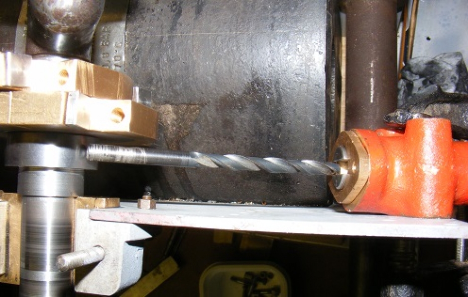
| 1 forum posts | Hi guys can anybody help me - I'm also building the 3 inch Burrell and struggling with the Plaistow drawings in inaccuracies and incompleteness ! I'm down in darkest Cornwall and as yet been unable to find anybody locally that can help. On Deric's photo above there are two what I think are 6ba bots immediately above the steam head on the spectacle plate - what are these for - there is obviously something bolted to the crankshaft side - what is this can't find anything on the drawings. Does anybody have a pipe work schematic I just don't know which pipe goes to what fitting ? Thanks in advance |
| RRMBK | 17/07/2018 20:40:26 |
| 159 forum posts 18 photos | Hi John. I have the same engine and share your frustration with the very poor standard of the drawings ! My steam manifold ( steam head ) is fitted with two bolts into the manifold which then pass through the spectacle plate and through a square plate with 4 holes in the corners, fitted on the other( front) side of the spectacle plate. This small square plate is then anchored to the spectacle plate with the two bolts above that you can see in the pic. I'm not good with photos and computers but if this doesn,t explain it come back to me. The square plate is shown at the bottom LH corner of drwg 109, but the drawing of the steam head shows all 4 holes as being located in the manifold which is clearly impossible because the plate would then block the entry of the manifold inlet fitting from the boiler.. So basically the two lower holes in the plate match the upper holes in the manifold and the two upper holes in the plate, bolt through the spectacle plate above the manifold. Kind regards bk. |


Please login to post a reply.
Magazine Locator
Want the latest issue of Model Engineer or Model Engineers' Workshop? Use our magazine locator links to find your nearest stockist!
Sign up to our Newsletter
Sign up to our newsletter and get a free digital issue.
You can unsubscribe at anytime. View our privacy policy at www.mortons.co.uk/privacy
Latest Forum Posts
- hemingway ball turner
04/07/2025 14:40:26 - *Oct 2023: FORUM MIGRATION TIMELINE*
05/10/2023 07:57:11 - Making ER11 collet chuck
05/10/2023 07:56:24 - What did you do today? 2023
05/10/2023 07:25:01 - Orrery
05/10/2023 06:00:41 - Wera hand-tools
05/10/2023 05:47:07 - New member
05/10/2023 04:40:11 - Problems with external pot on at1 vfd
05/10/2023 00:06:32 - Drain plug
04/10/2023 23:36:17 - digi phase converter for 10 machines.....
04/10/2023 23:13:48 - More Latest Posts...
- View All Topics
Support Our Partners


Shopping Partners
Subscription Offer

Latest "For Sale" Ads
- Reeves** - Rebuilt Royal Scot by Martin Evans
by John Broughton
£300.00 - BRITANNIA 5" GAUGE James Perrier
by Jon Seabright 1
£2,500.00 - Drill Grinder - for restoration
by Nigel Graham 2
£0.00 - WARCO WM18 MILLING MACHINE
by Alex Chudley
£1,200.00 - MYFORD SUPER 7 LATHE
by Alex Chudley
£2,000.00 - More "For Sale" Ads...
Latest "Wanted" Ads
- D1-3 backplate
by Michael Horley
Price Not Specified - fixed steady for a Colchester bantam mark1 800
by George Jervis
Price Not Specified - lbsc pansy
by JACK SIDEBOTHAM
Price Not Specified - Pratt Burnerd multifit chuck key.
by Tim Riome
Price Not Specified - BANDSAW BLADE WELDER
by HUGH
Price Not Specified - More "Wanted" Ads...
Get In Touch!
Do you want to contact the Model Engineer and Model Engineers' Workshop team?
You can contact us by phone, mail or email about the magazines including becoming a contributor, submitting reader's letters or making queries about articles. You can also get in touch about this website, advertising or other general issues.
Click THIS LINK for full contact details.
For subscription issues please see THIS LINK.
Digital Back Issues


Donate

 Register
 Log-in
Model Engineer Magazine
- Percival Marshall
- M.E. History
- LittleLEC
- M.E. Clock

ME Workshop
- An Adcock
- & Shipley
- Horizontal
- Mill

Subscribe Now
- Great savings
- Delivered to your door

Pre-order your copy!
- Delivered to your doorstep!
- Free UK delivery!
All Forum Topics > Traction engines > 3" Burrell build