Forum sponsored by:

Hick & Son Crank Overhead Engine
Nebie needs help
| Peter Wood 5 | 15/01/2014 14:23:32 |
| 94 forum posts 11 photos | I am currently building the above engine from Hemingway Kits, having completed a Stuart 10V, a Mount Cross Engine, A Vulcan Beam Engine and part completed a Sir William Pumping engine. This time I fear I may have bitten off more than I can chew. I have now got to the stage of making the connecting rod and have no idea how to proceed. In particular the 3/64'' slots for the bearing strap cotter pins seem impossible.
Having followed the Stuart Victoria thread I wonder if I could crave some of the same advice. Thanks Peter |
| Stub Mandrel | 15/01/2014 14:49:50 |
 4318 forum posts 291 photos 1 articles | Hi Peter, For Norden I had to make similar slots 1/16" wide. That extra 1/64" seems a lot! The slots will be hidden so they don't need to be perfect, although the end the key bears against needs to be correctly placed. After I finished my engine someone suggested drilling axially down from the curved surface for the bearing. This can remove a significant proportion of the metal the slot has to cross, and at the centre, the hardest part to reach. Now chain drill the slot with a 3/64" drill as accurately as you can. It may be worth drilling from each side in turn rather than trying to do so in one go. Now cross your fingers and using a 1mm end mill as fast as it will go and taking cuts of no more than 0.4mm or less gently remove the metal between the chain drilled holes. If you are lucky the tip of a flat but pointed (does that make sense?) diamond file will enter the slot and let you tidy it up. An alternative rout would be to make a chisel from gauge plate or silver steel with a short tip 3/64" thick and 3/32" broad. Bevel it so the cutting edge is at one, narrow end. A second with the cutting edge on a long side could be useful. You can either use this by hand to chip away between the drill holes or, if made on the end of a silver steel rod, you may be able to use in the mill with a gentle up down planing action. Final thought, as 1mm end mills snap very easily, an alternative would be to file a d-bit shape on the end of 3/64" silver steel, just for about 3mm. Make one at each end of the rod so you have a spare immediately to hand. This will be slower, but if carefully tempered will probably outlast and end mill (which will probably be far too long in the fluted section, and therefore too fragile). Neil P.S. I'm sure someone else will suggest spark erosion, and that's probably the best solution of all, but requires making a whole new machine.
|
| JasonB | 15/01/2014 15:11:00 |
 25215 forum posts 3105 photos 1 articles | Peter, take a look as Jo's thread on her S&P she has posted about wedge and cotter slots several times. I tend to drill out as much as possible, mill and then file with ground down needle files, these are all 1/16" wide. As for how to generally proceed with making the conrod I would take an overlength bit of 3/4x5/16 bar, clamp it to the mill table and machine it to the profile, you would have to flip it over at the end to do the other side of the outer webs and then finally mill or file them to the tapered shape, something like I did here
Edited By JasonB on 15/01/2014 15:28:11 Edited By JasonB on 15/01/2014 18:31:27 |
| Jeff Dayman | 15/01/2014 16:12:52 |
| 2356 forum posts 47 photos | Hi Neil, Re spark erosion, you could certainly make an EDM machine to do these slots, and in fact I did make one for similar jobs, to the Ben Fleming design. However, for a one time job it probably is not worthwhile. Many commercial mouldmaking and tool and die shops will do EDM work by the job, and Peter would likely be able to find a shop and get a quote without much trouble via google and/or yellow pages. When enquiring Peter should be sure to tell the shops he is working on steam models. Your method of drilling and milling to finish will certainly work, though, and is probably least expensive method to make the slots. One note- feed slowly when milling with small mills, with a .010" or .015" depth of cut. It would be wise to chain drill with new, good quality twist drills also, preferably drilling in the mill. JD Edited By Jeff Dayman on 15/01/2014 16:14:10 |
| Jeff Dayman | 15/01/2014 17:18:18 |
| 2356 forum posts 47 photos | Peter, something did not look right about the section XX view. I sketched up the rod in Solidworks and a jpeg of the drawing is as shown. The cross section hatched area should reach to each side, unlike the section on the hand drawn view as section XX. I don't think the height proportion on section XX is correct either. Hope the correct section AA view helps. JD |
| Peter Wood 5 | 16/01/2014 15:06:28 |
| 94 forum posts 11 photos | Gentlemen Thank you for all your advice. I had previously made similar slots of 1/16'' width by chain drilling and then carefully milling with a 1/16'' slot drill. With a lot of patience a reasonable result could be obtained without breaking too many mills. However as Neil notes in his first sentence, going down to 3/64'' seems a step too far. In addition I had not been able to find any mills under 1/16'' at my usual sources. I like the idea of making a d-bit out of silver steel and so I will get some at Ally Pally tomorrow, along with a stock of 3/64 drills!! Then I will practice on some scrap. Having put a lot of effort into shaping the con rod I don't want to start experimenting on it. The other problem I foresaw which you have identified was that of filing the slots to shape after drilling / milling. The tip of my precious Swiss files would just fit into a 1/16th slot but certainly not 3/64''. I never thought of grinding them down. to fit! I think I will have to invest in anew set also tomorrow. Looking at Jasons pictures it occurred to me that i might modify the ends of the con rod forks to receive circular bearing shells. I dread making split bearings in which one half is square and the other round and at this size the problems would be even greater. I know it is not strictly correct but I am not planning to enter any competitions. These are just memento for the grand children. Finally thanks for correcting the drawing Jeff. I will have to explore Solidworks. looks a useful tool. Peter |
| JasonB | 16/01/2014 15:19:17 |
25215 forum posts 3105 photos 1 articles | Peter if you need them MSC/J&L have 0.050", 3/64" and 1.2mm cutters J |
| Peter Wood 5 | 16/01/2014 19:56:29 |
| 94 forum posts 11 photos | Jason Gulp. I will need a new mortgage at those prices! Thanks anyway. Peter |
| JasonB | 16/01/2014 20:06:07 |
25215 forum posts 3105 photos 1 articles | Maybe its me but I did not think £14 for a double ended cutter that small was too bad a price, not much difference to two FC-3 cutters at list price |
| Jo | 16/01/2014 20:12:05 |
| 198 forum posts | At 1.2mm lets be honest you could drive a tank and full artillery regiment through such a huge hole! They are not in any way difficult. When I cut the slots on the S&P that Jason pointed you at earlier I had a major problem.. I foolishly initially cut them 0.6mm wide and then wasted a lot of time cutting them wider. Wider is easy. You can always find methods to make it a simple job more difficult or choose to use tools that are not up to the job When I scale the S&P down to 1/12th scale I will be doing slots 0.4mm by 2.3mm long. I think I know how to do them Jo |
| JasonB | 16/01/2014 20:15:32 |
25215 forum posts 3105 photos 1 articles | Should be an easy job now that you have the Sixis Mill |
| Jo | 16/01/2014 20:19:17 |
| 198 forum posts | No much easier by hand Jo |
| John Stevenson | 16/01/2014 20:26:25 |
 5068 forum posts 3 photos | Since MSC took J&L over their prices have become anywhere. You can't go on catalogue or web prices any more.
You ring them up and say I want a blab - blab cutter in carbide. yes sir that £82.78 each. Bugger off, that way too expensive
OK sir we can do this today for £21.87
Why should you have to do this ? Their interstate stub drills in 3.00 which are Chinese are dearer than a Dormer ? Average of £7.00 for a FC3 throw away cutter [ hint to J&L you are supposed to throw the cutter away when blunt, not the cutter and chuck ]
I used to spend £200 to £300 a month with them, in the last two months I have spent £35 on a new bandsaw blade and that's only because they do Lennox blades.
£3.52 for a 1mm cutter from Cutwel |
| Stub Mandrel | 16/01/2014 20:45:58 |
4318 forum posts 291 photos 1 articles | My problem is I can break 1mm cutters by looking at them. Neil |
| John Stevenson | 16/01/2014 21:17:18 |
5068 forum posts 3 photos | Mine arrive pre broken so it cuts the middle man out |
| Jo | 16/01/2014 21:24:57 |
| 198 forum posts | Why are you using a 1mm cutter? Wrong tool Jo
|
| Jeff Dayman | 16/01/2014 22:46:35 |
| 2356 forum posts 47 photos | Peter, if you think cutters are pricey, sit down before looking at quotes for buying a Solidworks license! I have a license of it for work, which pays it off gradually. It is great design software and very easy to use compared to other types of professional 3D modeling CAD software. JD |
| Peter Wood 5 | 17/01/2014 08:59:57 |
| 94 forum posts 11 photos | John The Cutwell prices are more realistic. Only problem is that they are straight shank and I have the quicklock? type of chuck which takes threaded cutters. Jo Stop being a tease! I like the approach you have used of chain drilling followed by sawing through and filing to shape. Seems infinitely less stressful than milling with a 1mm cutter. I am off to Ally Pally now and will be looking for some fine piercing saws and diamond files I can grind to size. Peter |
| John Stevenson | 17/01/2014 09:59:44 |
5068 forum posts 3 photos | Peter, Don't just go on the picture but click on the link as they do threaded and plain in the same lists
http://www.cutweltools.co.uk/files/ww/HSS%20A33.pdf
A bit dearer in the threaded but you expect that. £4.91 for a 1mm Edited By John Stevenson on 17/01/2014 10:00:37 |
| JasonB | 17/01/2014 10:11:13 |
25215 forum posts 3105 photos 1 articles | John does the black square not signify that they don't do 1mm in screwed shank ?? |


Please login to post a reply.
Magazine Locator
Want the latest issue of Model Engineer or Model Engineers' Workshop? Use our magazine locator links to find your nearest stockist!
Sign up to our Newsletter
Sign up to our newsletter and get a free digital issue.
You can unsubscribe at anytime. View our privacy policy at www.mortons.co.uk/privacy
Latest Forum Posts
- *Oct 2023: FORUM MIGRATION TIMELINE*
05/10/2023 07:57:11 - Making ER11 collet chuck
05/10/2023 07:56:24 - What did you do today? 2023
05/10/2023 07:25:01 - Orrery
05/10/2023 06:00:41 - Wera hand-tools
05/10/2023 05:47:07 - New member
05/10/2023 04:40:11 - Problems with external pot on at1 vfd
05/10/2023 00:06:32 - Drain plug
04/10/2023 23:36:17 - digi phase converter for 10 machines.....
04/10/2023 23:13:48 - Winter Storage Of Locomotives
04/10/2023 21:02:11 - More Latest Posts...
- View All Topics
Support Our Partners


Shopping Partners
Subscription Offer

Latest "For Sale" Ads
- Reeves** - Rebuilt Royal Scot by Martin Evans
by John Broughton
£300.00 - BRITANNIA 5" GAUGE James Perrier
by Jon Seabright 1
£2,500.00 - Drill Grinder - for restoration
by Nigel Graham 2
£0.00 - WARCO WM18 MILLING MACHINE
by Alex Chudley
£1,200.00 - MYFORD SUPER 7 LATHE
by Alex Chudley
£2,000.00 - More "For Sale" Ads...
Latest "Wanted" Ads
- D1-3 backplate
by Michael Horley
Price Not Specified - fixed steady for a Colchester bantam mark1 800
by George Jervis
Price Not Specified - lbsc pansy
by JACK SIDEBOTHAM
Price Not Specified - Pratt Burnerd multifit chuck key.
by Tim Riome
Price Not Specified - BANDSAW BLADE WELDER
by HUGH
Price Not Specified - More "Wanted" Ads...
Get In Touch!
Do you want to contact the Model Engineer and Model Engineers' Workshop team?
You can contact us by phone, mail or email about the magazines including becoming a contributor, submitting reader's letters or making queries about articles. You can also get in touch about this website, advertising or other general issues.
Click THIS LINK for full contact details.
For subscription issues please see THIS LINK.
Digital Back Issues


Donate

 Register
 Log-in
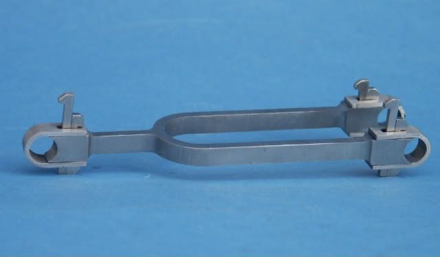
Model Engineer Magazine
- Percival Marshall
- M.E. History
- LittleLEC
- M.E. Clock

ME Workshop
- An Adcock
- & Shipley
- Horizontal
- Mill

Subscribe Now
- Great savings
- Delivered to your door

Pre-order your copy!
- Delivered to your doorstep!
- Free UK delivery!
All Forum Topics > Stationary engines > Hick & Son Crank Overhead Engine