Forum sponsored by:

Quick change NMTB system for milling machine
| Muzzer | 02/01/2014 22:37:50 |
 2904 forum posts 448 photos | My used Taiwanese Bridgeport clone milling machine has a NMTB30 taper for the spindle tooling. As I now live in Canada, this has been a bit of a hassle, since almost all tooling for these machines is R8 here. Tooling in general in North America is very expensive - it`s either locally made and expensive or it`s imported (Chinese or Indian, the usual suspects) with the price hiked up so it costs about twice as much as it would in the UK. I ended up buying most of my spindle tooling from the UK and was a lot better off even after duty and shipping. However, I now have a mixture of M10 and M12 threaded NMTB tooling. The NMTB30 has an ISO30 taper and a short parallel shank with either an M10 or M12 internal thread for a drawbar. I've become rather tired of having to swap over the drawbar from M10 to M12 each time I want to change from the M10 threaded drill chuck (drills, centre finder etc) to the M12 threaded collet chuck (milling cutters etc), so I started to think about quick change systems. The normal solution in N America is a power drawbar. This is basically an air powered impact driver mounted on top of the head. There is also an air solenoid that engages the impact driver with the top of the spindle before it starts to turn. This presumably works pretty well with R8 tooling but wouldn't be quite so effective with the NMTB and MT tooling which requires more encouragement to eject. It would also require a compressed air supply which I don't currently plan on installing. "Proper" quick change tooling used on CNC machines uses a pull stud mounted on each of the tools and a claw device that positively locks onto the stud and pulls it into the spindle (usually against some form of taper). There are also other systems that use a ball and ramp system rather like the concept you see used in industrial and garden hose couplings. Either way, these systems generally require a sprung draw bar to retain the tooling and some means of compression / ejection. Some quick patent searches come up with the obvious solutions, mostly expired long ago. I wasn't going to be inventing anything particularly novel here. I didn't fancy the impact driver approach , either air or electrical. It just sounded too messy and probably not appropriate for a fixed taper. The industrial pull stud equivalent of my NMTB system (called BT30 etc) requires space inside the spindle for the pull stud gubbins that simply doesn't exisit in my machine. I measured up the (tiny) space available in my spindle and got scheming (and modelling). The parallel shank on the NMTB30 doesn't actually contact the spindle bore, so apart from housing the M10/M12 thread it has no functional purpose in my setup. I could chop much of it off as long as there is enough thread remaining in the (hardened) body to accept a pull stud. By doing so, I would have a cavity of about 17mm diameter and around 30mm length in which to accommodate some gubbins of my own device. Here's what I came up with. A fairly conventional pull stud (to my own dimensions, by necessity), a mating socket with four captive 1/8" ball bearings, a sliding collar with a ramp to drive the balls into the groove in the pull stud and an o-ring to cause the collar to drag within the spindle cavity. Beyond that, a draw bar would extend up above the head. This would have a compression spring to keep the tooling engaged and an end stop and bearing bearing so that the draw bar and spring could be compressed by raising the spindle against it, to allow tool removal. Sounds simple enough but would require some critical machining. My skills are closer to the agricultural engineer than the watchmaker, so this would be a challenge... Edited By Muzzer on 02/01/2014 22:38:31 Edited By Muzzer on 02/01/2014 22:38:46 Edited By Muzzer on 02/01/2014 22:39:04 |
| Muzzer | 02/01/2014 22:43:22 |
2904 forum posts 448 photos |
Once I`d acquired some ball bearings from a local bike shop and a few 1/8" ball-ended slot drills, I had everything I needed to get started. The stepped outside profile and M10 thread was pretty straightforward using carbide indexable tooling and M10 die.
Boring the holes for the ball bearings required precise setup in the milling machine. The holes were cut with a ball-ended slot drill such that the 3.2mm diameter ball only emerges 0.9mm into the central bore at full engagement, otherwise the balls would fall out between tool changes. I set up the work individually for each hole using a center finder and the DRO and carefully bored to the precise depth. The cutter was slightly under size relative to the ball, so I moved the cutter to give an additional 0.1mm in all 4 X and Y directions. This worked well - the balls are free to move but aren't in any danger of falling out.
The pull stud had to be machined ``backwards`` ie with the large M10 or M12 thread at the tailstock end. I don`t have an M12 die any more(!), so had to set up my (imperial) Bantam to cut the M12 x 1.75 thread. Once you start cutting with this setup, you mustn`t disengage the half nuts. Then I turned the head of the stud using a parting tool and 1.6mm radius tool, before parting it off.
The final part of the core assembly is the closing collar. I machined this in the lathe using a small HSS boring bar and achieved a pleasing finish and accuracy. The groove on the outside is to house an o-ring. This provides some drag on the collar against the bore of the machine spindle to open and close the mechanism as the draw bar moves up and down against the spring. It seems to work well.
|
| Muzzer | 02/01/2014 22:47:24 |
2904 forum posts 448 photos | I realised quite early on that in order to make enough space in the spindle cavity for the mechanism, I would need to shorten the (non-functional) parallel shanks on each tool holder to accept the pull stud. I ended up removing about 10mm from the length. I heated the shanks up to red heat to make them machinable without affecting the main taper. I can still use the original drawbar(s) if I need to go back.
I obtained a 4" long die spring with 1/2" bore that seemed about right for the application. My estimation of the axial force I typically applied with the existing drawbars suggested that the spring rate should be of the correct order to allow a sensible adjustment of preload.
The drawbar has an adjustable tapered bronze nut at the top end that butts up against a hard stop. This allows the spring to be compressed when you force the quill up against it through the last 5mm or so of return travel, releasing the pull stud.
With the component parts hardened and tempered and the parts assembled, I checked that releasing the compression spring before the pull stud was fully inserted did not result in broken parts. This worst case condition puts a fair stress on the collar in particular but it and the studs seem able to tolerate it. I can now change tooling in the time it takes to drop one tool holder out and insert another, which is of the order of a second or so. That's a significant improvement on the endless palaver with the spanner, mallet and swapping drawbars which took nearer a minute. I will have to find something else to swear at now. That was my metal therapy for the Xmas break! HNY to everyone. Merry
|
| Muzzer | 02/01/2014 22:55:24 |
2904 forum posts 448 photos | This is the only photo of the assembled clamp assembly. Not much to see finally - space was limited.
|
| Andrew Johnston | 03/01/2014 10:49:59 |
 7061 forum posts 719 photos | Wow, that looks excellent, definitely at the top end of the agricultural emporiums I'd posit. Of course the downside is you now need to think of some more tooling to make, or there's a danger you might have to start on a model engine. Regards, Andrew |
| mgnbuk | 03/01/2014 12:21:41 |
| 1394 forum posts 103 photos | I don't want to detract from what appears to be a nicely made modification, but what kind of force does your spring exert to retain the tool ? All the machines I have worked on using spring retained arrangements use a substantial Belleville spring stack & I would expect the pull exerted on a 30 ISO tool to be in the order of a tonne - the Cincinatti Sabres at work use a Belleville arrangement & IIRC the manual states that the 40 ISO tool has a 1.5 tonne drawbar pull & 50 ISO units I designed in the past using a hydraulic clamping arrangement had a 3.5 tonne pull. Skimping here is not something you want to be doing - you really don't want the tool pulling out under load ! I have seen 40 ISO spring retained tools pulled out even with the Belleville arrangement.- which is one reason why I used hydraulic clamping on the spindle I designed. The air-powered, screw type arrangements work fine with steep taper tooling - the drawbar is captive, so the tool is positively ejected. They have the advantage of not putting any axial force on the spindle bearings when the tool is ejected, which is what happens in most spring retained arrangements (it is possible to arrange the release cylinder so that this doesn't happen, though I have only seen one Spanish machine that did this). Matchmaker CNC turret mills (Shizuoka machines fitted with Posidata contols in the UK) fitted with the Dana automatic toolchanger used a screw drawbar with 30 ISO tooling - I don't recall having had any tool retention or release issues on the couple of machines I retrofitted at my last employment. Regards. Nigel |
| Trevor Wright | 03/01/2014 12:50:24 |
 139 forum posts 36 photos | Muzzer, Nice one. Intrigued at the release mech. - was looking at the photos and wondering how you were going to work the release. Have used a pneumatic release on 30 taper holders in the past and the noise was horrendous, especially when releasing and the taper had bitten. Trevor |
| Muzzer | 04/01/2014 01:53:45 |
2904 forum posts 448 photos | Nigel Yes, I looked at this when I was figuring out what was possible and what was required. As you doubtless know, "proper" BT30 tooling is capable of handling high power and very high speeds (over 15krpm seems not unheard of). However, this is a venerable, fairly lightweight BP clone which has limited capability and will only be using fairly small tooling of barely adequate quality at modest speeds. I'm certainly not pretending that this would be suitable for any industrial applications on the likes of the machinery you mention. I did some very rough fag packet calculations to estimate what force I was applying through the drawbars and that came out at around the 50-70kg mark ie not far off the weight of a smallish adult. Requires a blow or two from the mallet to remove it. My die spring allegedly has a spring rate of around 150lb/in in old (ie USA) units, so with an inch or so of preload should be similar to what I was applying manually, although with little to prevent the tool pulling out under load beyond that. The "Mach-1" quick change system for R8 tooling is the only one I could find on sale that still uses this ball and ramp concept, probably for the reasons you give. However, there simply isn't room in there for the kind of positive locking mechanism normally found in modern BT30-equipped industrial machines and I wouldn't have the capability to attempt the components required anyway. The Mach-1 claims a 600lb preload from a 1" x 4" die spring, so it's providing more pull force which is fair enough, given the applications they claim it's good for. I agree with your concern about whether or not I have sufficient preload and this is something I need to look at more closely. I noted that I can obtain a "heavy duty" version from the same supplier which has twice the spring rate and also get a shorter version which will further increase that. Now that I seem to have constructed it and it appears to work, I need to convince myself that it is fit for purpose. Thanks for your comments and experience! Muzzer |
| Muzzer | 05/01/2014 04:55:04 |
2904 forum posts 448 photos | Posted by Andrew Johnston on 03/01/2014 10:49:59:
...the downside is you now need to think of some more tooling to make, or there's a danger you might have to start on a model engine. Regards, Andrew It'll be a cold day in hell when that happens I suspect. For me, machine tools and all the other workshop equipment have always been a means for building, mending and modifying real life things like full sized engines. I just don't have the patience (or interest) to make scale models and if I did, they wouldn't be a pretty sight - I'm more Mad Max than Faberge! "Model engineering" actually means "amateur machine shop" to me. Merry |
| mgnbuk | 06/01/2014 13:14:32 |
| 1394 forum posts 103 photos | Hi Muzzer, Rather than examine the force applied to hold the tool in the spindle, maybe consider the force required to remove the tool from the spindle under operating conditions ? With a screw drawbar, you would have to apply enough force for the weakest element to fail – most likely stripping of the M10 or M12 drawbar thread. You could get an idea of the force required to strip such a thread if you have access to a hydraulic press – tap a through hole in a piece of plate the thickness of your drawbar engagement, screw in a bolt loosely to the drawbar engagement depth & try to press the bolt through the plate, monitoring the force on the press at the point the thread fails. With a spring applied collet, the tool will start to move out of the taper when you exceed the applied spring force – it will not have to move far before the collet reaches its release point and the tool is suddenly free. With your 130lb force spring, I suspect that you could lever the tool out of the spindle with a short crowbar between the tool flange and the spindle nose – I doubt that you could do that with a screw drawbar fitted ! Vibration from cutting may overcome the friction in the thread & thrust washer of a screw drawbar causing it to loosen, but this would most likely be a gradual process & the tool would probably not be totally released suddenly – you would most likely hear and/or see the tool coming loose & be able to stop the spindle before the tool came free. Springs, though, can be affected by vibrations & if you are unlucky enough to generate a frequency that causes the spring to resonate you may find the applied force suddenly reduces. Add in axial forces generated by positive tool geometry, helix angles, etc. working to pull the tooholder from the spindle – the possibilities for a rapid and unexpected ejection of a rotating tool seem a lot greater. I know very little about spring design & performance, though what I have read suggests it is a complex topic. I suspect that one of the reasons Belleville (disc) springs are used is because of resonance. Also, failure of one disc in a stack of a couple of dozen (or more) would have less of an effect then a coil fracturing on a die spring. Using a number of short die springs in a stack may have a very different resonant frequency than using one long spring - but then you may as well go the whole hog & use a Belleville stack ! I don’t think you want to be looking to double your spring force, I think you want to be looking for a 5 fold or more increase to be reasonably safe. Perhaps bear in mind that steep taper tooling is pretty mature technology & that certain designs of tool retention seem to predominate. That would suggest to me that, at some point in the past, research and/or hard won experience found optimum solutions for drawbar pull forces (and reliable methods for applying those forces) for various size tapers. I appreciate that a commercial product has to meet different design criteria to something you design for your own use – I was always aware of liabilities when I was coming up with solutions and probably over-engineered as a result – but I would not relish being chased around my garage by a tool that had made a successful bid for freedom ! £0.02 Nigel |
| Muzzer | 07/01/2014 20:09:14 |
2904 forum posts 448 photos | Hi Nigel Thanks for your two pence worth! Yes, I appreciate the spring could allow the tool to come free if it were pulled down with enough force during machining in a way that a threaded drawbar wouldn't. I'm taking the Mach-1 system as guidance here and I'm also aware that if I increase the spring rate too much it may become rather tough to remove, as well as stressing the parts if a mis-insertion occurs. As I said, my tooling is fairly low power and low speed, so I'm not going to emulate the capabilities of top end equipment. Generally, I'm expecting that if the spring fails it's likely to do so during the point of greatest compression ie during tool insertion. I use my machine fairly infrequently compared to a professional tool (it's pretty much out to long grass now), so spring fatigue is unlikely to be a concern and at the modest speeds I use, I'm not expecting vibrations to result in unexpected tool release. Hopefully I won't discover otherwise!! Muzzer |
| Muzzer | 22/03/2014 05:39:32 |
2904 forum posts 448 photos | I've now had a 700lb/in "super heavy dooty" die spring in there for some time now with a decent preload. I've also done some stress testing to check for any signs of movement and to see what the machine will do. Looks pretty good. I plunged a 3/4" hogging cutter right through a piece of 3/4" loominum rectangular stock for several inches at 1000rpm and something around 10-15 IPM feed. This must generate a fair amount of pull-out. The inverter tripped at one point (I've changed the settings now as they were too low) but otherwise this is probably about as harsh as I will get. I've also run a 12mm slot drill along a 12" length of mild steel, followed by a tee-slot cutter, generating a sizeable tee slot in 2 passes. I wouldn't have done this dry but it didn't complain and there were no dings. I've been using this quick change system quite intensively now for the best part of 3 months and I can honestly say this is one of the best additions I've made to the machine. Along with the DRO. And the power feed. And the VFD.... Murray |
| S Goldsmith | 26/01/2015 18:51:49 |
| 2 forum posts | Muzzer, This is excellent and just what I was looking for. I have exactly the same issue that you had but with some bt / int30 tooling that has a mix of 10mm and 12mm drawbar thread, so I feel your pain with regards to tool changing. This incidentally is on an old Balding Beaver Model A milling machine circa 1950 - 60 at a guess. (http://www.lathes.co.uk/beaver/page2.html) Certainly going to look into employing this method, great work! SRG |
| Muzzer | 28/01/2015 10:19:18 |
2904 forum posts 448 photos | Good luck with it SRG. If you decide to have a go at something similar, you are welcome to copies of my models and drawings to give you some ideas. I had to pack up my workshop in September, ahead of moving back to the UK, by which time I had put in a fair number of hours and many tool changes using this system. It's been a great help to me and I've not had any kind of breakage or failure in that time. I'm very pleased with it. Murray |
| John Stevenson | 28/01/2015 13:21:45 |
 5068 forum posts 3 photos | I am working on an auto toolchanger at the moment using BT30 and from research the pull needed is between 900 and 1200 pounds force BT 40 is actually double that at 1800 to 2200 according to the books and I tested my Beaver CNC which has NMTB40 and it gave a reading of 2400 but it's recently had new springs in it. Edited By John Stevenson on 29/01/2015 10:45:23 |
| Muzzer | 28/01/2015 16:31:12 |
2904 forum posts 448 photos | Thanks for the cross reference John. Looking forward to seeing what your changer looks like when it's done. I haven't tried to measure the pull force but I'm probably compressing the spring about an inch at the most (including preload) which suggests about 700lb from my "super heavy dooty" die spring. Any more than that and I'd struggle to force the feed handle up to release the toolholder. I'd also be worried about breaking the pull stud / clutch assembly, especially if it weren't properly engaged when releasing the spring, which is the worst case it has to cope with. If you do a fag packet estimation of the ratio of the radius of the feed pinion to the length of the feed lever on a BP, that gives you an idea of the sort of force you'd need to exert with a machine like mine. Looking at some skanky pictures from ebay, it looks as if the pinion has a radius of about 1" and a typical feed lever is about 10" long, so that would require about a 70lb / 30kg lift on the lever if I'm right.That doesn't sound a million miles off. A proper BT30 system is probably capable of bigger spindle loads in a decent machine that can exploit it, but my weedy BP clone is probably not up there. 1200lb is over half a tonne. Murray Edited By Muzzer on 28/01/2015 16:32:43 |
| Nick_G | 28/01/2015 16:36:18 |
 1808 forum posts 744 photos | . Impressive.
Nick |
| John Stevenson | 29/01/2015 02:00:59 |
5068 forum posts 3 photos | Murray. I will be less constrained by design like you as I don't have a spindle to make it fit into.
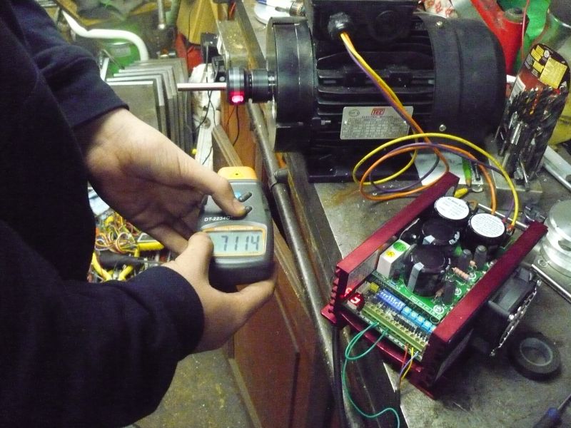
Currently I'm awaiting a special motor from Italy which will be a 4 Kw 2800 rev 2 pole, and 3 Kw 960 rev, 6 pole, two speed motor. All they are sending is the stator and rotor but the rotor has got a larger bore than standard. The idea is to fit a new shaft that carries the BT30 taper, The new bottom end will have double angular contact bearings fitted, water cooled and two CREE work lights recessed inside. The top housing will be a housing with floating bearing and incorporate a 6" air cylinder which will give about 2200 pounds of force at 80 psi for the release which is far more than needed for a BT30 but it can be reduced with a regulator.
This will have to run on 440v 3 phase which isn't a problem and with a 440v 3 phase in and 440v 3 phase out vector inverter rated at 5 Kw and running this at 20hz low to get the most torque and 140 hz high to get speed it will give me from 380 rpm to 7,800 rpm using just the motor as a spindle.
None of this is new, the commercial woodworking routers have been doing this for 50 years up to 12,000 rpm. The only bit out of the ordinary is getting the Italians to supply a two speed with the high rated inverter windings on the 2 pole bit.
As this will never run anything bigger than a 12mm cutter under CNC it will work out well and the whole assembly can be under computer control, something not easily done if you use a single speed motor and rely on belts for the torque increase. 40% [50 hz / 20Hz ] of 3kw, the low speed is still 1.8 Kw which is far greater than most hobby type machines have at their disposal.
This is an earlier motor converted with just the new bottom housing and a built in ER32 collet system.
And the work lights.
These are off a 5v wall wart, really need to drop them to about 3.5 volts.
Edit. Similar ones to this have run for over 9 years now running about 8 hours shifts with 5 of these on a big multi head router and the only problems I have had is I had to fit a new spindle on the end one when they whacked part of the gantry frame with it [ bad programming ] Edited By John Stevenson on 29/01/2015 02:06:19 |
| KWIL | 29/01/2015 10:08:00 |
| 3681 forum posts 70 photos | Posted by Andrew Johnston on 03/01/2014 10:49:59:
...the downside is you now need to think of some more tooling to make, or there's a danger you might have to start on a model engine. Regards, Andrew It'll be a cold day in hell when that happens I suspect. For me, machine tools and all the other workshop equipment have always been a means for building, mending and modifying real life things like full sized engines. I just don't have the patience (or interest) to make scale models and if I did, they wouldn't be a pretty sight - I'm more Mad Max than Faberge! "Model engineering" actually means "amateur machine shop" to me. Merry Muzzer
May I politely ask why, if this is your view, what are you doing here on a Model Engineeing Forum? Edited By KWIL on 29/01/2015 10:11:04 |
| John Stevenson | 29/01/2015 10:52:14 |
5068 forum posts 3 photos | Because "Muddle Engineering " is a misnomer. The yanks [ hawk - spit - ding ] have it right when they call their magazine Home Shop Machinist because not everyone is into models.
For many a workshop exists to support another hobby whatever that is.
Dave Fenner once stated that the magazines with pictures of things like bikes and cars on the cover outsold the ones with pictures of things like dividing heads etc, which for me given that all my friends [ all three ] have workshops but none make "models"
Long, short is we are forced to buy MEW because there isn't another mag. I have said for a long while that now it's been split off from ME it ought to loose the "Model" in the title to make it more acceptable to other hobbies. |


Please login to post a reply.
Magazine Locator
Want the latest issue of Model Engineer or Model Engineers' Workshop? Use our magazine locator links to find your nearest stockist!
Sign up to our Newsletter
Sign up to our newsletter and get a free digital issue.
You can unsubscribe at anytime. View our privacy policy at www.mortons.co.uk/privacy
Latest Forum Posts
- hemingway ball turner
04/07/2025 14:40:26 - *Oct 2023: FORUM MIGRATION TIMELINE*
05/10/2023 07:57:11 - Making ER11 collet chuck
05/10/2023 07:56:24 - What did you do today? 2023
05/10/2023 07:25:01 - Orrery
05/10/2023 06:00:41 - Wera hand-tools
05/10/2023 05:47:07 - New member
05/10/2023 04:40:11 - Problems with external pot on at1 vfd
05/10/2023 00:06:32 - Drain plug
04/10/2023 23:36:17 - digi phase converter for 10 machines.....
04/10/2023 23:13:48 - More Latest Posts...
- View All Topics
Support Our Partners


Shopping Partners
Subscription Offer

Latest "For Sale" Ads
- Reeves** - Rebuilt Royal Scot by Martin Evans
by John Broughton
£300.00 - BRITANNIA 5" GAUGE James Perrier
by Jon Seabright 1
£2,500.00 - Drill Grinder - for restoration
by Nigel Graham 2
£0.00 - WARCO WM18 MILLING MACHINE
by Alex Chudley
£1,200.00 - MYFORD SUPER 7 LATHE
by Alex Chudley
£2,000.00 - More "For Sale" Ads...
Latest "Wanted" Ads
- D1-3 backplate
by Michael Horley
Price Not Specified - fixed steady for a Colchester bantam mark1 800
by George Jervis
Price Not Specified - lbsc pansy
by JACK SIDEBOTHAM
Price Not Specified - Pratt Burnerd multifit chuck key.
by Tim Riome
Price Not Specified - BANDSAW BLADE WELDER
by HUGH
Price Not Specified - More "Wanted" Ads...
Get In Touch!
Do you want to contact the Model Engineer and Model Engineers' Workshop team?
You can contact us by phone, mail or email about the magazines including becoming a contributor, submitting reader's letters or making queries about articles. You can also get in touch about this website, advertising or other general issues.
Click THIS LINK for full contact details.
For subscription issues please see THIS LINK.
Digital Back Issues


Donate

 Register
 Log-in
Model Engineer Magazine
- Percival Marshall
- M.E. History
- LittleLEC
- M.E. Clock

ME Workshop
- An Adcock
- & Shipley
- Horizontal
- Mill

Subscribe Now
- Great savings
- Delivered to your door

Pre-order your copy!
- Delivered to your doorstep!
- Free UK delivery!
All Forum Topics > Workshop Tools and Tooling > Quick change NMTB system for milling machine