Forum sponsored by:

Where do Buffer Nuts Go?
Inside or outside? Challenge the accepted wisdom!
| Stub Mandrel | 19/10/2013 14:54:17 |
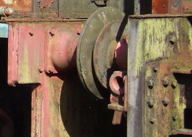
 4318 forum posts 291 photos 1 articles | It pays to check. Read any ME series about making a model loco and when you get to the buffers you will almost certainly get to the bit where it says that "in prototypical practice the nuts on the stock fixings are always on the outside of the buffer beams". I came across this statement again today, then later I noted I made my shunter with the nut on the inside. Reviewing pictures of Hudswell Clarke diesel shunters, every example I can find (where you can tell) the nuts are on the inside. In the picture above the loco at left is a Hudswell Clarke, I don't know what loco it is up against, but the latter has the buffer nuts inside - and less than a turn of thread visible. I propose a nationwide survey of prototype locos - what percentage have the nuts on the inside, and is it consistent by maker? Neil |
| Stub Mandrel | 19/10/2013 15:51:21 |
4318 forum posts 291 photos 1 articles | Other interesting features in this picture: The buffer beam is two (slightly mismatched) plates. The buffer head has a pad riveted to it. This is probably either leather or rubber as the engine is one modified to work in a zero-spark environment (oil refinery). Both nice little details guaranteed to lose marks in a competition Talking to myself... Neil |
| David Haynes | 26/10/2013 23:49:04 |
| 168 forum posts 26 photos | This is the buffer detail on L&HR Barclay 2333 "David". Nuts on the outside and lock nuts for good measure!
But this is the detail on the LHR Hunslet Austerity 'Cumbria', with bolt heads on the outside...
Some more for Neil's survey, only another 493 to go...
Dave
Edited By David Haynes on 27/10/2013 00:05:27 Edited By David Haynes on 27/10/2013 00:12:27 |
| DMB | 27/10/2013 00:19:56 |
| 1585 forum posts 1 photos | Some years back,wandering around loco shed @ Bluebell Rly, Sheffield Park. I was looking for very obvious small details like holes in driving axles, presumably to save weight. Locos originating from different companies/diff. types like 0-4-0/0-6-0/4-6-0 had none or diff. dia through holes in axles. But every axle driving or otherwise that had no hole had what looked like a freshly turned centre for mounting between centres on a wheel lathe. Bet that was done in Bluebells works as that feature was common to and identical on all makes of loco.However, I bet they were all originally slightly different. John |
| DMB | 27/10/2013 00:20:05 |
| 1585 forum posts 1 photos | All the various railway works would have machined and fitted just about every part differently but to imitate on your model is likely to become harder in future if preservation groups/ museums make their own small changes to suit their methods.
John. Edited By DMB on 27/10/2013 00:40:56 |
| Nicholas Farr | 27/10/2013 07:32:30 |
 3988 forum posts 1799 photos | Hi Neil, something that I've never really took any notice of, but heres a couple. This is GER E4.
This is the New Tornado.
Both have the nuts outside. Regards Nick. |
| Stub Mandrel | 27/10/2013 10:21:18 |
4318 forum posts 291 photos 1 articles | Thanks folks. I suspect the main determinant is the accessibility at the back of the buffer beam. I was once watching a GWR loco, probably a Manor, on the West Somerset Railway against the sky and though I was seeing things until I realised it had hollow driving axles! Until then I always thought they were solid, I have never seen them as tubes on a model. Neil |
| DMB | 27/10/2013 15:56:08 |
| 1585 forum posts 1 photos | Seems like a good idea to me - poke bolts in from back then you can easily see to screw nuts on @ the front. If a nut works loose (unlikely, but suppose could happen) then much more easily noticed @ front rather than hidden under running board + behind buffer beam. |
| fizzy | 27/10/2013 19:36:47 |
 1860 forum posts 121 photos | Im guessing it was all down to who held the spanner on the day! (unless design dictated orientation). |


Please login to post a reply.
Magazine Locator
Want the latest issue of Model Engineer or Model Engineers' Workshop? Use our magazine locator links to find your nearest stockist!
Sign up to our Newsletter
Sign up to our newsletter and get a free digital issue.
You can unsubscribe at anytime. View our privacy policy at www.mortons.co.uk/privacy
Latest Forum Posts
- *Oct 2023: FORUM MIGRATION TIMELINE*
05/10/2023 07:57:11 - Making ER11 collet chuck
05/10/2023 07:56:24 - What did you do today? 2023
05/10/2023 07:25:01 - Orrery
05/10/2023 06:00:41 - Wera hand-tools
05/10/2023 05:47:07 - New member
05/10/2023 04:40:11 - Problems with external pot on at1 vfd
05/10/2023 00:06:32 - Drain plug
04/10/2023 23:36:17 - digi phase converter for 10 machines.....
04/10/2023 23:13:48 - Winter Storage Of Locomotives
04/10/2023 21:02:11 - More Latest Posts...
- View All Topics
Support Our Partners


Shopping Partners
Subscription Offer

Latest "For Sale" Ads
- Reeves** - Rebuilt Royal Scot by Martin Evans
by John Broughton
£300.00 - BRITANNIA 5" GAUGE James Perrier
by Jon Seabright 1
£2,500.00 - Drill Grinder - for restoration
by Nigel Graham 2
£0.00 - WARCO WM18 MILLING MACHINE
by Alex Chudley
£1,200.00 - MYFORD SUPER 7 LATHE
by Alex Chudley
£2,000.00 - More "For Sale" Ads...
Latest "Wanted" Ads
- D1-3 backplate
by Michael Horley
Price Not Specified - fixed steady for a Colchester bantam mark1 800
by George Jervis
Price Not Specified - lbsc pansy
by JACK SIDEBOTHAM
Price Not Specified - Pratt Burnerd multifit chuck key.
by Tim Riome
Price Not Specified - BANDSAW BLADE WELDER
by HUGH
Price Not Specified - More "Wanted" Ads...
Get In Touch!
Do you want to contact the Model Engineer and Model Engineers' Workshop team?
You can contact us by phone, mail or email about the magazines including becoming a contributor, submitting reader's letters or making queries about articles. You can also get in touch about this website, advertising or other general issues.
Click THIS LINK for full contact details.
For subscription issues please see THIS LINK.
Digital Back Issues


Donate

 Register
 Log-in
Model Engineer Magazine
- Percival Marshall
- M.E. History
- LittleLEC
- M.E. Clock

ME Workshop
- An Adcock
- & Shipley
- Horizontal
- Mill

Subscribe Now
- Great savings
- Delivered to your door

Pre-order your copy!
- Delivered to your doorstep!
- Free UK delivery!
All Forum Topics > General Questions > Where do Buffer Nuts Go?