Forum sponsored by:

Rob Roy 3 1/2" gauge tank locomotive - anybody built one?
| Phil H 1 | 26/05/2012 13:52:52 |
| 128 forum posts 46 photos | I have decided to continue with the construction of Rob Roy and will be seeking advice and tips from people who have built one. Oh - one tip that is probably a bit too late is the cylinder machining/ drawing error. I machined the cylinder blocks about 25 years ago to the wrong port face dimension!! My first question relates to the firing of the boiler. Has anybody got one running on gas?
|
| AndyP | 26/05/2012 23:05:53 |
| 189 forum posts 30 photos | I am building one as a first loco, runs on air ! If that is the error that means the valve rods don't line uo with the gear then snap - cranked adapters on the end of the valve rods solved mine. There is a thread covering a working gas fired Rob Roy here |
| Doubletop | 27/05/2012 02:30:08 |
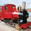
 439 forum posts 4 photos | Phil I see you've decided to complete your Rob Roy. As it happens I can probably help you with your question on gas firing here. My thread on gas firing a Rob Roy And the full story here Near the end YouTube videos of it running, on gas. I'll admit it probably isn't as good as being coal fired, but I've never tried coal firing it. Its quick to get get running and quick to get packed up at the end of the day. Happy to help with any questions but please post them over on the HMEM site to keep the info in one place Pete
Edited By Doubletop on 27/05/2012 02:31:54 |
| Springbok | 27/05/2012 04:05:53 |
 879 forum posts 34 photos | Hi Built a Rob Roy but eventually listed over 2 pages of errors in the drawings. Nice little loco when finished. Bob |
| Phil H 1 | 27/05/2012 11:25:55 |
| 128 forum posts 46 photos | Yes Andy, the cranked cross heads might be required and yes Bob - I'll keep a look out for the corrections. Ive seen various lists posted on the net so I will proceed with caution. Pete - the pictures look excellent and the thread on gas firing looks very helpful. I notice that I should be ok regarding traction. I didn't realise that this engine was so capable. I will take some pictures of the parts that I have completed so far but there won't be many of them. My first job is to put some protective film over the drawings and I will order some steel. Phil H
|
| Phil H 1 | 27/05/2012 23:04:36 |
| 128 forum posts 46 photos | Some pictures - as promised. The frames have been very badly attacked by evil rust so I will need to start again. One of them will at least serve as a good drilling jig. The wheels, axles and axle boxes have a little bit of surface rust that can be cleaned off.
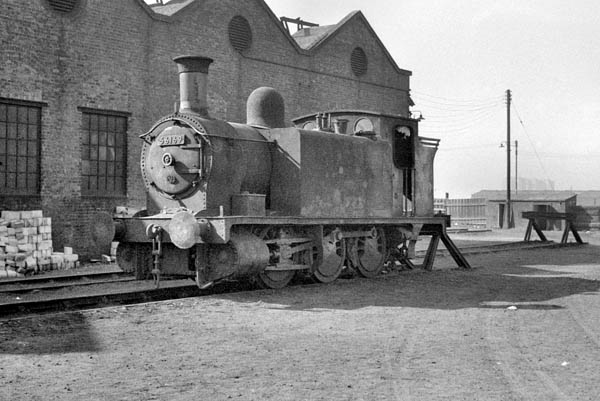
The real thing. I copied this from a book called 'The McIntosh Locomotives of the Caledonian Railway 1895 - 1914'. I would like to find more pictures to use as a guide for the finished article. I noticed a superb front view in Pete's posts. I understand that this is a simple model but there are a couple of details that are probably quite easy to copy. For example, the coupling rods have a pivot joint to the trailing wheels and the buffer heads look a little bit larger than the model drawing dimensions that I have.
One of the cylinder sets partially finished. I machined these 25 years ago.
One of the wheels and a set of axle bxes made from BMS with brass bushes.
Yep - I was sad enough to scoop out the back of each wheel and file the spokes to an oval cross section. |
| Springbok | 28/05/2012 03:26:42 |
879 forum posts 34 photos |
I know it is cheating but Bob |
| Doubletop | 28/05/2012 08:37:25 |
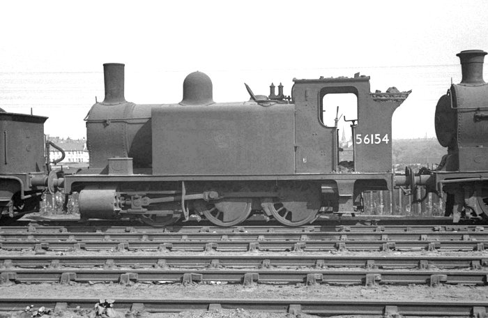
439 forum posts 4 photos | Phil Thanks for the picture I searched and searched the internet for a picture and came up with nothing like your picture from the book. The best I've seen. All I could come up with was
(image on original site) And here and here
Looks like you've made a good start there, abeit a while back Pete Edited By Doubletop on 28/05/2012 08:38:02 Edited By Doubletop on 28/05/2012 08:42:41 |
| Phil H 1 | 28/05/2012 21:08:32 |
| 128 forum posts 46 photos | Excellent shots Pete. They confirm the larger - what looks like modified buffer heads, the 8 fixings for each buffer stock and position of the engine number on the smokebox door.. These should'nt be too difficult to copy. I have the saddle casting and I had wondered how it should connect up to the smokebox tube. The pictures clearly show an all in one, riveted saddle/ smokebox assembly so I can now machine the casting correctly. An interesting question for you. What temperature does the smokebox of the model reach? For example, if I carefully machine the saddle and join it to the brass tube using a combination of screws and solder - would soft solder survive? Phil H. |
| Springbok | 29/05/2012 00:04:53 |
879 forum posts 34 photos | Phil In one word NO soft solder is a no go anywhere near a boiler. screws should be more than adequate for fixing the smokebox to the saddle. Bob |
| Doubletop | 29/05/2012 11:19:21 |
439 forum posts 4 photos | Phil Like Bob I'd suggest screws you'll be taking it apart a few times to get it set up. The valve chests aren't that easy to get to and the inlet and exhaust pipework has to come out to get the covers off. And no soft solder it does get hot. Pete
|
| Phil H 1 | 29/05/2012 13:08:39 |
| 128 forum posts 46 photos | Bob/ Pete, Great help guys this is exactly the sort of tips and advice that I'm looking for. Ive just ordered the plain BMS for the frames. I had considered the new fangled laser cut versions but I couldn't bring myself round to placing the order. As you said Bob its sort of cheating isn't it? Phil H |
| Phil H 1 | 09/06/2012 22:54:57 |
| 128 forum posts 46 photos | Guys, Any tips on painting before I assemble the buffer beams and main horns? I read an article a few years ago that proposed the use of primer during the riveting stage. A rather messy process but it was suggested that the primer prevents oil and grease from staining and ruining the paintwork that is applied at a later stage. Also, the book suggests normal cellulose paint. Is that ok considering your earlier comments on soft solder on the smokebox. Do the frames get very hot too? Phil H |
| Springbok | 10/06/2012 06:34:58 |
879 forum posts 34 photos | Phil
Use an etching primer on your frame and basically anything else that you wish to paint at a future date, Smokebox a good high temp black paint, boiler cleading (not misspelt) once on use a good quality paint. Please look at this site not cheap but good Bob |
| Doubletop | 10/06/2012 07:46:10 |
439 forum posts 4 photos | When I painted my Rob Roy it was the first time I had painted a loco. I used heatproof paint and painted the inner frames red and the outer frames black. Once that was done I baked the frames. It turned out that I hadn't baked them enough and the constant work and copious amounts of oil when getting it going the paint job started to look pretty shoddy. In the end I gave up and left it until I got the loco running properly and then completely stripped it down again , removed all the paint and had the frames powder coated. In order to do that each of the places where components joined were masked off to maintain dimensional integrity. The powder coating company provided the high temp masking tape. Here's the link to the section of my thread on the powder coating I’d suggest, the issue of heat isn't a problem the powder coat is baked at about 200degC. Outside of the boiler won't be that, even at 80psi. The trouble heat proof paint is it doesn't gain its oil and solvent resistance until its been well baked. Until then it will come off at the slightest hint of oil. I now use a hooded gas barbeque with a temp gauge in the hood. It will take a whole frame and the baking can be kept at about 200deg for an hour without SWMBO complaining about the stink in the kitchen and the next Sunday roast tasting distinctly dodgy. I'd imagine others have painted many more locos than me but from my experience, I'm on my third now, I'd leave it as late as possible. I had my Rob Roy apart about 5 times before I was happy with it; the paint gets decidedly tattier each time. Pete
|
| Redpiperbob | 10/06/2012 08:18:57 |
 92 forum posts 41 photos | Hi Phil "Oh - one tip that is probably a bit too late is the cylinder machining/ drawing error. I machined the cylinder blocks about 25 years ago to the wrong port face dimension" I am just about to start cutting the cylinders and valve chests for my Rob Roy so can you point me in the right directioon to moify the above error before I start. Thanks Bob |
| AndyP | 10/06/2012 10:57:23 |
| 189 forum posts 30 photos | One list of errors here and another wordier one here both cover the relevant gotcha. Andy |
| Phil H 1 | 10/06/2012 12:07:35 |
| 128 forum posts 46 photos | Thanks guys, I agree with Bob that rust is an enemy. My first set of frames (made when I was 16) are heavily rusted and totally useless now (apart from being a good drilling jig for the new ones). I like the idea of high temperature paint from Pete too. I think I will get the book from Mr Vine but continue to make loose parts until I've read the book. I've machined the horns, polished both sides of the frame steel and cut most of the buffer beam parts (all drenched in oil of course). Phil H |
| Phil H 1 | 10/06/2012 12:35:53 |
| 128 forum posts 46 photos | 'I am just about to start cutting the cylinders and valve chests for my Rob Roy so can you point me in the right directioon to moify the above error before I start. Thanks Bob' Bob, I've looked at the list from Andy and there are a few mods mentioned in the book 'Rob Roy & William' by Martin Evans. Some might be repeated but thought they were worth mentioning. 1. Check the height of the horizontal stretcher. The book suggests raising this by 1/16" to give more clearance to the eccentric straps. 2. Cut a 'U' in the upper left vertical stretcher to give clearance to a possible blowdown valve. 3. It suggests using cast bronze for the connecting rod big end bearings instead of drawn bronze to give a longer life. 4. The flange on the valve crosshead is removed and its boss increased by 1/32" giving more support to the valve spindle? 5. The oil check valve is fitted with a plunger instead of the spring bearing directly on the ball. 6. Bushes are used on the backplate and smokebox plate instead of threading the plates themselves. 7. The safety valve vent holes are increased in size from No 55 to No 52. The spring locating pin or spindle is reduced in diameter to accomodate the above mod. I think I saw a string on this issue somewhere else and these changes are a puzzle to me i.e., I have worked in a design office for 30 years. All the mods would take less than a few hours to correct including a mod record (either electronically drawn or by hand). I wonder why we don't do it? Phil H
|
| Doubletop | 10/06/2012 23:50:12 |
439 forum posts 4 photos | There was another I'm aware of and that’s the lack of a stretcher between the cylinders and the inlet/exhaust in effect become a stretcher. Mine wouldn't go round some of the tighter corners and when I measured the gap between the frames at the cylinders it was too wide at the bottom ( the saddle act as a stretcher at the top). I drilled through a pair of opposing cylinder mounting holes, made a piece of 1/4" silver steel the correct spacing, drilled and tapped the ends and put it between the frames. That ensured the correct spacing at the bottom. Sorry no picture for some reason Pete |


Please login to post a reply.
Magazine Locator
Want the latest issue of Model Engineer or Model Engineers' Workshop? Use our magazine locator links to find your nearest stockist!
Sign up to our Newsletter
Sign up to our newsletter and get a free digital issue.
You can unsubscribe at anytime. View our privacy policy at www.mortons.co.uk/privacy
Latest Forum Posts
- *Oct 2023: FORUM MIGRATION TIMELINE*
05/10/2023 07:57:11 - Making ER11 collet chuck
05/10/2023 07:56:24 - What did you do today? 2023
05/10/2023 07:25:01 - Orrery
05/10/2023 06:00:41 - Wera hand-tools
05/10/2023 05:47:07 - New member
05/10/2023 04:40:11 - Problems with external pot on at1 vfd
05/10/2023 00:06:32 - Drain plug
04/10/2023 23:36:17 - digi phase converter for 10 machines.....
04/10/2023 23:13:48 - Winter Storage Of Locomotives
04/10/2023 21:02:11 - More Latest Posts...
- View All Topics
Support Our Partners


Shopping Partners
Subscription Offer

Latest "For Sale" Ads
- Reeves** - Rebuilt Royal Scot by Martin Evans
by John Broughton
£300.00 - BRITANNIA 5" GAUGE James Perrier
by Jon Seabright 1
£2,500.00 - Drill Grinder - for restoration
by Nigel Graham 2
£0.00 - WARCO WM18 MILLING MACHINE
by Alex Chudley
£1,200.00 - MYFORD SUPER 7 LATHE
by Alex Chudley
£2,000.00 - More "For Sale" Ads...
Latest "Wanted" Ads
- D1-3 backplate
by Michael Horley
Price Not Specified - fixed steady for a Colchester bantam mark1 800
by George Jervis
Price Not Specified - lbsc pansy
by JACK SIDEBOTHAM
Price Not Specified - Pratt Burnerd multifit chuck key.
by Tim Riome
Price Not Specified - BANDSAW BLADE WELDER
by HUGH
Price Not Specified - More "Wanted" Ads...
Get In Touch!
Do you want to contact the Model Engineer and Model Engineers' Workshop team?
You can contact us by phone, mail or email about the magazines including becoming a contributor, submitting reader's letters or making queries about articles. You can also get in touch about this website, advertising or other general issues.
Click THIS LINK for full contact details.
For subscription issues please see THIS LINK.
Digital Back Issues


Donate

 Register
 Log-in
Model Engineer Magazine
- Percival Marshall
- M.E. History
- LittleLEC
- M.E. Clock

ME Workshop
- An Adcock
- & Shipley
- Horizontal
- Mill

Subscribe Now
- Great savings
- Delivered to your door

Pre-order your copy!
- Delivered to your doorstep!
- Free UK delivery!
All Forum Topics > Beginners questions > Rob Roy 3 1/2" gauge tank locomotive - anybody built one?