Forum sponsored by:

Portable Engine Model Engineer Article by Tony Webster
| David Clark 1 | 07/03/2012 11:26:33 |
 3357 forum posts 112 photos 10 articles |
I have started this thread to publish any questions, errors found and corrections in Tony Webster's Portable Engine series. Some of the content from this thread may be used in Model Engineer.
regards David
PS Any unsigned posts by me will be replies from Tony Webster.
Edited By David Clark 1 on 07/03/2012 14:00:39 |
| David Clark 1 | 07/03/2012 11:27:35 |
3357 forum posts 112 photos 10 articles |
The boiler barrel is eight inches long, with 3/8in. cut off the firebox end for one third of the circumference.
I advised not to try squaring up the ends of the boiler barrel in the lathe because it is difficult to hold in the chuck.
Edited By David Clark 1 on 07/03/2012 11:47:51 |
| David Clark 1 | 07/03/2012 11:27:53 |
3357 forum posts 112 photos 10 articles |
There are five bushes in the boiler, there is one each side of the barrel at the front so there is a spare for a hand pump.
The holes for the eight corner stays for fixing the horns should be 7/32in. dia. ie. the 1/4in. dia. is reduced slightly in diameter to provide a 'head' to stop them falling through when silver soldering. Head on the outside which makes it a two operation job. Reduce to 7/32in. dia. part off, chuck the other way round to centre, drill and tap 4BA. (It also cleans the bronze surface for silver soldering.)
Edited By David Clark 1 on 07/03/2012 11:48:07 |
| David Clark 1 | 07/03/2012 11:56:50 |
3357 forum posts 112 photos 10 articles |
The 7/16in. tube should be 20 swg, standard thickness from your friendly model engineer's stockist. Jason B should be assured that if too thin a wall section tube is fitted, the tube is likely to collapse inwards, in other words flatten. The pressure is on the outside in this case and copper is less strong in compression. This would not cause a catastrophic collapse and would most likely happen when the boiler is tested to twice boiler pressure. This is why boilers are tested to twice boiler pressure. Subsequent tests are to one and a half times boiler pressure.
In typesetting my hand written dimensions for publication, in the end section to the right of the drawing on page 364, the 11/16in. dimension to the first row of stays should be from the top of the foundation ring as shown in the door plate drawing to the left. Also the 1/4in. should be for the foundation ring only and not include the firebox wrapper plate. The front to back location of the water gauge bush and manifold will be detailed in a further instalment of the series. There is no harm in having a static connection to the water gauge, ie a pressure gauge where there is no movement of steam or water through the manifold. I agree that there must not be a connection to the blower or injector etc. from the water gauge. This would have a misleading effect on the water level in the water gauge. |
| JasonB | 07/03/2012 13:14:35 |
 25215 forum posts 3105 photos 1 articles | Thanks David good to try and keep all these things in one place. A few more questions regarding the boiler drawing in 4425. 1. Depth of flanges to inner firebox and throat plate 2. How far does inner firebox protrude below foundation ring 3. Drawing says 2off regulator bush, where does the second one fit 4. Should there be any thickening pad inside the boiler to mount the crankshaft bearings 5. Should there be blind bushes to mount the firedoor Hinge 6 Confirmation of an available thickness for copper in substitution for the 3/32" and 1/8" thicknesses shown on drawing.
Thanks, Jason Edited By JasonB on 07/03/2012 13:15:54 |
| JasonB | 17/03/2012 09:59:14 |
25215 forum posts 3105 photos 1 articles | Cylinder drawing issue 4426. 1. No setting out positions for the 10No valve chest stud holes or will they be detailed with the valve chest. 2. Text says machine valve face back to lines 1 & 2 but drawing shows it at least 1/32 away from them. 3.Length of cylinder and protrusion of end faces not shown on drawing but can be found in text. 4. No depth for steam port slots 5. Brass tube, I'll wait to see what teh text says before commenting. From the comments in about the last issue I got the impression there was going to be another boiler drawing has this been missed or is it to follow out of sequence? In 4426 it would seem the boiler is "complete " and tested yet the details mentioned two posts above have not been covered?? J |
| JasonB | 30/03/2012 20:52:04 |
25215 forum posts 3105 photos 1 articles | Errors & Ommisions 4427 1. Width of Valve chest given as 3/8" but should be more like 1.5" 2. No length given for piston rod 3. Crosshead, no thickness given, probaly 5/16" to suite the slidebars but the 3/8" spigot is not shown to suit that.
David there are now three issues worth of queries, any chance of some answers?? as you did say this thread would be for corrections!! Jason |
| JasonB | 30/03/2012 21:42:26 |
25215 forum posts 3105 photos 1 articles | more 4427 1. No depth for piston ring groove 2. No length of 1/4x40 thread on piston rod 3. No depth for cut out in cross head, looks about 1/2" |
| David Clark 1 | 30/03/2012 22:33:56 |
3357 forum posts 112 photos 10 articles | Hi There Tony Webster has been away. I will chase him up Monday but I don't know when he is back. regards David
|
| Adam Gregory 1 | 02/04/2012 08:03:26 |
 20 forum posts 11 photos | Hi all Any chance of a few more pictures of finished components or close ups of the finished model, to make it easier to understand some of the text and diagrams. |
| David Clark 1 | 02/04/2012 09:01:13 |
3357 forum posts 112 photos 10 articles | Hi There I have a few photos to publish but most are pretty poor quality. regards David
|
| JasonB | 02/04/2012 09:16:07 |
25215 forum posts 3105 photos 1 articles | David if they are a bit too poor for actual printing what about just adding to this thread so those that need the reference have access to them. Another thing that would help would be to try and syncronise the drawings with the text for example the description of the cylinder covers in the latest issue is very hard to follow but I'm sure once the drawings appear hopefully in the following issue the text will make a lot more sense.
J |
| David Clark 1 | 02/04/2012 09:46:43 |
3357 forum posts 112 photos 10 articles | Hi There We don't have rights to put unpublished photos on the websites. Rear cylinder cover drawing is in 4428, front cover in 4429. regards David |
| JasonB | 02/04/2012 10:08:16 |
25215 forum posts 3105 photos 1 articles | Why can't it be done like the Darjeeling ref photos, none of them have been published, You would only need to Ask Tony if it was OK. Failing that if I see it at another exhibition I could take a load of photos and stick them in an album J |
| David Clark 1 | 02/04/2012 10:36:29 |
3357 forum posts 112 photos 10 articles | Hi Jason I took the Darjeeling photos. They are my copyright. That is why they are on here. regards David |
| JasonB | 02/04/2012 13:03:10 |
25215 forum posts 3105 photos 1 articles | Fair enough. This wil take anyone interested to the only pic I have of the engine, there is another one on the net that I will dig out the link for when I have a bit more time Edited By JasonB on 02/04/2012 13:04:00 |
| David Clark 1 | 02/04/2012 13:29:48 |
3357 forum posts 112 photos 10 articles | Hi There I do have some photos that I took at exhibitions. I will dig them out. regards David |
| Nicholas Farr | 02/04/2012 20:39:16 |
 3988 forum posts 1799 photos | Hi, I have put a photo that I took of Tony's engine when on display at Sandown, in my album named Portatable Engine, if anyone is interested in viewing it. It is similar to JasonB's link, but at a slightly different angle. Regards Nick Edited By Nicholas Farr on 02/04/2012 20:55:43 |
| Mike Wainwright | 07/04/2012 07:26:29 |
| 149 forum posts 8 photos | Is there a full set of drawinging available to go with this series that will have all corrections included. |
| JasonB | 07/04/2012 07:44:33 |
25215 forum posts 3105 photos 1 articles |
Posted by Mike Wainwright on 07/04/2012 07:26:29:
Is there a full set of drawinging available to go with this series that will have all corrections included.
Sorry could not resist. It would be nice if a lot of the newer models being published in the mag could be added to the MHS range of plans but somehow I don't see it happening, though most people contemplating a build in the future would likely track down the back issues anyway which would have the drawings in so why pay twice unless they had all revisions. J |
Please login to post a reply.
Magazine Locator
Want the latest issue of Model Engineer or Model Engineers' Workshop? Use our magazine locator links to find your nearest stockist!
Sign up to our Newsletter
Sign up to our newsletter and get a free digital issue.
You can unsubscribe at anytime. View our privacy policy at www.mortons.co.uk/privacy
Latest Forum Posts
- *Oct 2023: FORUM MIGRATION TIMELINE*
05/10/2023 07:57:11 - Making ER11 collet chuck
05/10/2023 07:56:24 - What did you do today? 2023
05/10/2023 07:25:01 - Orrery
05/10/2023 06:00:41 - Wera hand-tools
05/10/2023 05:47:07 - New member
05/10/2023 04:40:11 - Problems with external pot on at1 vfd
05/10/2023 00:06:32 - Drain plug
04/10/2023 23:36:17 - digi phase converter for 10 machines.....
04/10/2023 23:13:48 - Winter Storage Of Locomotives
04/10/2023 21:02:11 - More Latest Posts...
- View All Topics
Support Our Partners


Shopping Partners
Subscription Offer

Latest "For Sale" Ads
- Reeves** - Rebuilt Royal Scot by Martin Evans
by John Broughton
£300.00 - BRITANNIA 5" GAUGE James Perrier
by Jon Seabright 1
£2,500.00 - Drill Grinder - for restoration
by Nigel Graham 2
£0.00 - WARCO WM18 MILLING MACHINE
by Alex Chudley
£1,200.00 - MYFORD SUPER 7 LATHE
by Alex Chudley
£2,000.00 - More "For Sale" Ads...
Latest "Wanted" Ads
- D1-3 backplate
by Michael Horley
Price Not Specified - fixed steady for a Colchester bantam mark1 800
by George Jervis
Price Not Specified - lbsc pansy
by JACK SIDEBOTHAM
Price Not Specified - Pratt Burnerd multifit chuck key.
by Tim Riome
Price Not Specified - BANDSAW BLADE WELDER
by HUGH
Price Not Specified - More "Wanted" Ads...
Get In Touch!
Do you want to contact the Model Engineer and Model Engineers' Workshop team?
You can contact us by phone, mail or email about the magazines including becoming a contributor, submitting reader's letters or making queries about articles. You can also get in touch about this website, advertising or other general issues.
Click THIS LINK for full contact details.
For subscription issues please see THIS LINK.
Digital Back Issues


Donate

 Register
 Log-in
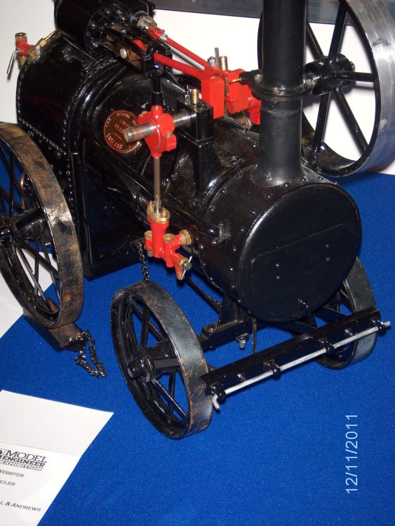
Model Engineer Magazine
- Percival Marshall
- M.E. History
- LittleLEC
- M.E. Clock

ME Workshop
- An Adcock
- & Shipley
- Horizontal
- Mill

Subscribe Now
- Great savings
- Delivered to your door

Pre-order your copy!
- Delivered to your doorstep!
- Free UK delivery!
All Forum Topics > Model Engineer. > Portable Engine Model Engineer Article by Tony Webster