Forum sponsored by:

No. of divisions
| Nobby | 11/09/2011 00:21:35 |
 587 forum posts 113 photos | Hi.
How is the dial divided up please. I want to add one to my s7 Mk1 Mine looks about 7/8" per rev.
Regards Nobby |
| John Stevenson | 11/09/2011 00:41:58 |
 5068 forum posts 3 photos | Nobby, Can't answer 100% correctly on how many divisions but I do know it has internal gearing so the dial move a set length per turn and not once per turn. Robin has more info than I have. John S. |
| ady | 11/09/2011 02:05:54 |
| 612 forum posts 50 photos | Is that a wee brush on the handle side of the dial to keep the gremlins out? I just put a digital vernier on my cross slide. Doesn't look as nice but backlash is eliminated and cuts are good for 1-200ths of a mm Edited By ady on 11/09/2011 02:08:13 |
| JasonB | 11/09/2011 13:21:41 |
 25215 forum posts 3105 photos 1 articles | I think its a straight knurl not a brush seal
J |
| Nobby | 13/09/2011 22:37:44 |
587 forum posts 113 photos | Hi Ady Thank you for reply .I know I can use the the handwheel on the leadscrew 125 divisions but you have to turn the gears as well . I suppose I could go digital? some how Regards Nobby |
| Anthony Rhodes | 18/09/2011 05:08:40 |
| 21 forum posts 31 photos | Posted by Nobby on 11/09/2011 00:21:35:
Hi.
How is the dial divided up please. I want to add one to my s7 Mk1 Mine looks about 7/8" per rev.
Regards Nobby Nobby,
It would probably be useful if you were to mention the article published in the latest issue of Home Shop MAchinist, September-October 2011, p. 26 - 35. There was also an earlier version of the article published in Engineering in Miniature but I don't know the daye or issue number for that release.
This is an article by Graham Meek. It tells how to build a micrometer dial for the carriage handwheel. The example discussed specifically was for a Myford Auper7 but he points out that the principles can be applied to any lathe.
The special feature of this design is that, since the carriage traverses an inconvenient distance for each revolution of the hand wheel. ther is an internal gear system which makes the micrometer dial rotate at a differen rate than does the handwheel so tha it reads actual distance traversed instead of a decimal value of the rotation of the hand wheel.
Per Gray's article the carriage travel per revolution of the hand wheel is .866". It would be inconvenient to have a micrometer dial marked out in 86.6 divisions to indicate 0.01" units. The internal gearing makes the dial rotate more slowly than the hand wheel so that when the handwheel has rotated one full revolution the dial will have rotated .866 revolutions by which means it reads the actual distance traversed rather than parts of a revolution of the hand wheel.
The picture at the start of this thread is straight out of the article and is marked with 100 divisions with each 5th mark a bit longer than the singles and each 10th mark noted with numbers for tenths of an inch. Gray gives the gearing to accomplish the reduced rotation of the dial for correct decimal inches and also provides the same information to read out in millimeters with divisions down to 1/4 mm.
In the article Gray states that the the gearing has an error of 0.43% (actually 4.35/1000 on a dial marked in hundreths). It would be possible to get that down to 0.17% error but it would require very special gears which can only be cut by hobbing. (J.S. original gearing 26/28 x 26/28, better 26/28 x 27/29. 27 on 26 pitch circle, 29 on 28 pitch circle.) This would actually fit because the gears would be the same size as the ones Gray specifies, I can generat numbers which can get he error down to .077% but I don't know if the gears could be fitted within the mechanism as designed.
So, to recap, 100 divisions indicating .01" or 100 divisons indicating .25 mm used with alternative gearing.
Anthony Edited By Anthony Rhodes on 18/09/2011 05:10:36 |
| Anthony Rhodes | 18/09/2011 07:20:12 |
| 21 forum posts 31 photos | In the article Gray states that the the gearing has an error of 0.43% (actually 4.35/1000 on a dial marked in hundreths). It would be possible to get that down to 0.17% error but it would require very special gears which can only be cut by hobbing. (J.S. original gearing 26/28 x 26/28, better 26/28 x 27/29. 27 on 26 pitch circle, 29 on 28 pitch circle.) This would actually fit because the gears would be the same size as the ones Gray specifies, I can generat numbers which can get he error down to .077% but I don't know if the gears could be fitted within the mechanism as designed. Did some more thinking about this. It turns out that almost ideal gearing is 26/30 x 28/28 (the extra 28/28 is necessary to return the same axis as the original drive). Results in an error of .077%. The question is whether the 30 will fit?
I believe the original gear train for the metric dial was 29/31 x 29/31 which had an error of 0.54%. Alternative gearing 33/29 x 31/31 results in an error of 0.012%. Same question, will the 33 fit?
Anthony |
| John Stevenson | 18/09/2011 09:18:09 |
5068 forum posts 3 photos | What DP are the gears ? You can just get a 30T on a 28 blank, not a pretty tooth form but still an involute and workable. This has been draw in in 20 DP just for reference, on the right is a big standard 28T gear, on the left is a corrected gear with 30 teeth on the same blank. 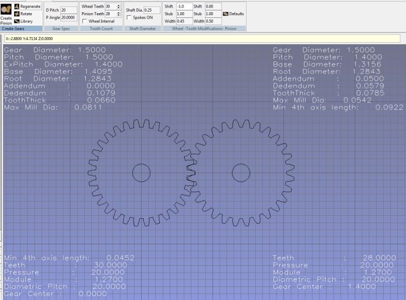 Click on picture to enlarge. John S. Edited By John Stevenson on 18/09/2011 09:18:57 |
| Nobby | 18/09/2011 16:16:00 |
587 forum posts 113 photos | Hi Tony & John Thank you for info on this . I wont be able to change gearing on the apron . I will give it some more thought. Meanwhile i will try and upgrade the adjustable carriage stop to indicate .001" I have a platform under the stop with fixed rule & for loading home made gauges to save using my best slips. Posted in one of my albums. What's .866 " in metric ? that's a thought Regards Nobby |
| Anthony Rhodes | 18/09/2011 16:22:54 |
| 21 forum posts 31 photos | Posted by John Stevenson on 18/09/2011 09:18:09:
What DP are the gears ?
You can just get a 30T on a 28 blank, not a pretty tooth form but still an involute and workable.
------------------------------ John S. Edited By John Stevenson on 18/09/2011 09:18:57 John,
That was my first thought but it probably isn't necessary.
The inch version of the micrometer dial uses 36 DP gears. The first and last gears in the train are coaxial with the hand wheel shaft. Original train is 26/28 x 26/28. New train would be 28/28 x 26/30. Increases the radius occupied by the train by one tooth depth (0.027777777"). I expect it would fit within thedesign as is but I haven't actually checked.
Same story with the metric version which uses 40 DP gears. Original train is 29/31 x 29/31. New train would be 31/31 x 29/33. Again increases the radius occupied by one tooth depth (0.025").
There is some benefit for amateur construction to not have to deal with special form gears.
Anthony |
| Anthony Rhodes | 18/09/2011 16:28:52 |
| 21 forum posts 31 photos | Posted by Nobby on 18/09/2011 16:16:00:
Hi Tony & John Thank you for info on this . I wont be able to change gearing on the apron . I will give it some more thought. Meanwhile i will try and upgrade the adjustable carriage stop to indicate .001" I have a platform under the stop with fixed rule & for loading home made gauges to save using my best slips. Posted in one of my albums. What's .866 " in metric ? that's a thought Regards Nobby Nobby,
.866" x 25.4 = 21.9964 mm but the rotation you want to deal with is related to 25 mm, not 1". The new factor is 0.879856 of 25 mm.
Anthony |
| John Stevenson | 18/09/2011 17:14:08 |
5068 forum posts 3 photos | Nobby, You don't have to change gears in the apron, the gears in question are inside the handwheel. John S. |
| John Stevenson | 18/09/2011 17:32:35 |
5068 forum posts 3 photos | You can get 0.866 with a 13/15 setup, or multiples of. John S. |
| Anthony Rhodes | 18/09/2011 23:38:20 |
| 21 forum posts 31 photos | As John says, the gears are inside the handwheel. The mechanism is a variation on the concept used to provide both inch and metric micrometer dials on the cross feed screw. Not common on inexpensive lathes but not at all unusual on machines such as Hardinge, Nonarch, Clausing, Nardini (I believe), etc.
John, your correct of course about the 13/15, just half the tooth counts of the 26/30, but many people aren't happy with very low tooth counts and two of the gears are coaxial to the hand wheel shaft. On the other hand, it occurs to me, the drive could be from A to 15 followed by 13 to B where A and B are the same tooth count and the 13 and 15 are both cut to a 14 pitch circle, or A, 13, and 15 are all cut to standard pitch circles and B is cut to a -2 pitch circle.
Aside from needing the coaxial gears to be large enough to fit over the center shaft, there's no preference for large or small DP. Looking at the drawings in the article it appears to me as if two 20 tooth 24 DP gears axial to the hand wheel shaft and and a cluster of 24 DP 15 and 13 tooth gears both cut to a pitch circle of 0.700" would be an ideal solution. This gives 28/15 x 13/28 = 0.86666666666666 = perfect result.
Your thoughts?
Anthony |
| John Stevenson | 18/09/2011 23:57:52 |
5068 forum posts 3 photos | Anthony PM sent |
| Nobby | 19/09/2011 17:32:53 |
587 forum posts 113 photos | Hi John
Cheers mate .
Regard Nobby
|
| Nobby | 21/09/2011 23:39:38 |
587 forum posts 113 photos | Hi Rob I misunderstood the from the start .I just wanted to put a dial direct on the standard handwheel on my S7 Mk. 1 I have another problem now with Srewcutting 10 TPI on my 1912 Drummond . I will post thread & see if you our anybody can help Its driving me mad ???? Regards Nobby |
| ady | 21/09/2011 23:46:45 |
| 612 forum posts 50 photos | 10tpi 8tpi leadscrew? 8 x 1.25 = 10tpi so. 20/25 or 40 headstock 50 leadscrew? |
| Anthony Rhodes | 22/09/2011 02:12:29 |
| 21 forum posts 31 photos | Posted by ady on 21/09/2011 23:46:45:
10tpi
8tpi leadscrew? 8 x 1.25 = 10tpi
so.
20/25
or
40 headstock 50 leadscrew? ady,
I started to respond to this but suddenly realized I'd confused theissue and you had it correct in the first place.
20/25 x .125" = .10" = 10 TPI. Any 4/5 ratio will do.
Edited By Anthony Rhodes on 22/09/2011 02:13:30 Edited By Anthony Rhodes on 22/09/2011 03:23:50 |
| Nobby | 22/09/2011 11:49:54 |
587 forum posts 113 photos | 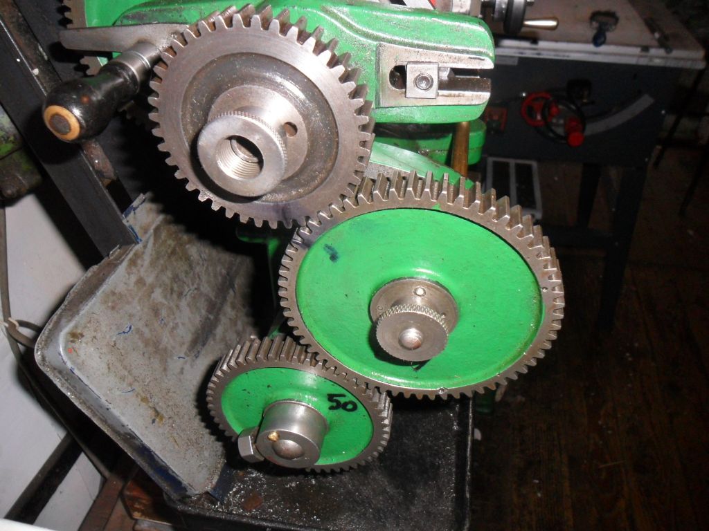  The gear train was no problem 40 - 60 idle- 50 leadscrew as photo .When engaging screwcutting lever photo on a test peice After disengaging lever the the 2'nd cut did not line up . On my Exe lathe I sold there was no problem . I know i can use the revering trick I have no reverse on this lathe . I suppose if I put the pedal back on I could use this trick Can I add a threading indicator some how . ? Regards Nobby |
Please login to post a reply.
Magazine Locator
Want the latest issue of Model Engineer or Model Engineers' Workshop? Use our magazine locator links to find your nearest stockist!
Sign up to our Newsletter
Sign up to our newsletter and get a free digital issue.
You can unsubscribe at anytime. View our privacy policy at www.mortons.co.uk/privacy
Latest Forum Posts
- *Oct 2023: FORUM MIGRATION TIMELINE*
05/10/2023 07:57:11 - Making ER11 collet chuck
05/10/2023 07:56:24 - What did you do today? 2023
05/10/2023 07:25:01 - Orrery
05/10/2023 06:00:41 - Wera hand-tools
05/10/2023 05:47:07 - New member
05/10/2023 04:40:11 - Problems with external pot on at1 vfd
05/10/2023 00:06:32 - Drain plug
04/10/2023 23:36:17 - digi phase converter for 10 machines.....
04/10/2023 23:13:48 - Winter Storage Of Locomotives
04/10/2023 21:02:11 - More Latest Posts...
- View All Topics
Support Our Partners


Shopping Partners
Subscription Offer

Latest "For Sale" Ads
- Reeves** - Rebuilt Royal Scot by Martin Evans
by John Broughton
£300.00 - BRITANNIA 5" GAUGE James Perrier
by Jon Seabright 1
£2,500.00 - Drill Grinder - for restoration
by Nigel Graham 2
£0.00 - WARCO WM18 MILLING MACHINE
by Alex Chudley
£1,200.00 - MYFORD SUPER 7 LATHE
by Alex Chudley
£2,000.00 - More "For Sale" Ads...
Latest "Wanted" Ads
- D1-3 backplate
by Michael Horley
Price Not Specified - fixed steady for a Colchester bantam mark1 800
by George Jervis
Price Not Specified - lbsc pansy
by JACK SIDEBOTHAM
Price Not Specified - Pratt Burnerd multifit chuck key.
by Tim Riome
Price Not Specified - BANDSAW BLADE WELDER
by HUGH
Price Not Specified - More "Wanted" Ads...
Get In Touch!
Do you want to contact the Model Engineer and Model Engineers' Workshop team?
You can contact us by phone, mail or email about the magazines including becoming a contributor, submitting reader's letters or making queries about articles. You can also get in touch about this website, advertising or other general issues.
Click THIS LINK for full contact details.
For subscription issues please see THIS LINK.
Digital Back Issues


Donate

 Register
 Log-in
Model Engineer Magazine
- Percival Marshall
- M.E. History
- LittleLEC
- M.E. Clock

ME Workshop
- An Adcock
- & Shipley
- Horizontal
- Mill

Subscribe Now
- Great savings
- Delivered to your door

Pre-order your copy!
- Delivered to your doorstep!
- Free UK delivery!
All Forum Topics > Manual machine tools > No. of divisions