Forum sponsored by:

Make your own timing pulleys
without a milling machine or cutter
| John McNamara | 27/08/2011 17:34:00 |
 1377 forum posts 133 photos | Hi All
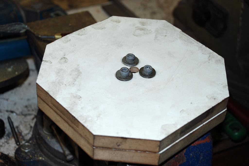
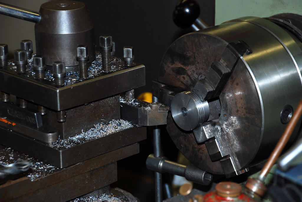
Make your own timing pulleys without a milling machine or cutter. For a while now I have been working on a possible drive system using timing pulleys for gearing. To get higher ratios you need more than one stage of gearing, given the size of timing gears available from suppliers. The typical maximum number of teeth is around 60 for a timing pulley in T5 size (5mm pitch), the minimum being 10 teeth, the above pairing yielding a ratio of 6 to 1. However the above pairing is not optimal with less than 4 teeth engaged on the 10 tooth pulley, due to the different diameters (the contact area can be increased using an idler wheel). To get higher ratios with stock gears multiple stages will give an almost unlimited range of gear ratios; the downside is each stage adds backlash to the system in addition to the errors introduced by the supporting shafts and bearings. Where there is room available to fit larger size gears; fewer stages will result, reducing the inevitable errors induced in any system. I am talking of timing pulleys with more than the 60 teeth in T5 size, Available from suppliers. Some suppliers do supply larger. However many do not. I pondered how to make gears with high tooth counts inexpensively. The most obvious method was to turn a disk of Aluminium or steel and using a suitable indexing head cut the teeth one by one using a milling machine. Ok if you have the equipment; and taking into account the cost of metals not that inexpensive in larger sizes. I then started to think if there was another way? Moulding came to mind. Certainly some commercial suppliers supply molded pulleys. How could a mould be made? And then it struck me use a belt to make a timing pulley! Belts are not very expensive. There is a very wide range available, from 48 teeth to 1955 teeth in T5 from one suppliers range, maybe 200 different sizes. For all but small pulleys below 48 teeth we can make our own; below 48 teeth that the cost from commercial suppliers is quite reasonable. Take for example a pulley with 720 teeth A Handy half degree radial pitch with a diameter of approximately 229.2mm. Or a huge 1955 teeth with a diameter of 622mm. (Ideal for the astronomers and their telescope mounts). Even with and a mill not an easy assignment to make; both are difficult to index accurately, and a fair amount of metal is used. With the above thoughts in mind I propose the following method which uses an actual timing belt to mould a gear. The belt will not be damaged in the process. One belt with the correct number of teeth will be required for each size pulley to be made. Rubber belts are not suitable (they will stick to epoxy) most are polypropylene anyway so not really a problem. Timing belts are actually a remarkable piece of engineering they are molded around a precision ground steel mandrel. They all have steel, nylon or sometimes Kevlar or other high tech fiber reinforcement. The reinforcement is continuous spiraling round and round the belt, there is only one start and one finish to the spiral. The tooth profile is formed to less than .0005” overall they are made to very high tolerance. I wondered how we could tap into that accuracy. Some sort of tooling would be required to support the belt and centre it with the steel shaft collar that is to be molded in, the simpler the better. I assume that most likely only one or two units will be required. This is not a commercial alternative process; it is for “One offs”. First the steel shaft mounting collar was rough turned with an undersize bore. The collar was also drilled and tapped for 3 x M6 cap screws to be used to secure the centre in the mould and allow fine boring in position. For the mould I have used melamine coated MDF scraps that were to hand. A backing piece and an edge piece with a large hole (about 10 mm less than the timing belt diameter) were cut using woodworking tools. The edge piece was securely screwed to the backing piece. (Drill a bare clearance hole in the edge piece for the screws and countersink both sides, to accommodate any bulging of the backing piece when the screws are driven in. MDF must always be pre drilled if you want it to sit flush) The shaft mounting collar was then mounted in the centre of the MDF mould with 3 M6 cap screws and washers. Ideally I would have liked a face plate to mount the mould on for finish turning in the lathe. I do not have one so used a large 4 jaw chuck. As shown in the attached photos the shaft mounting collar was centered in the lathe using a dial indicator. Once set it was a simple matter to bore the steel collar to final shaft size, skim turn the rest of the OD of the collar just to make sure it was dead centre and the faces planar and turn the inside edge of the edge piece to an exact fit with the timing belt. I also skimmed the back of the mold to correct a slight wobble. (I wish I had that face plate). The result was that we had everything including the belt concentric, all turned in one setting on the lathe. The belt just slipped in snugly with light finger pressure. Once all was rechecked the pattern was removed from the chuck. We were ready to pour! Continued next post Edited By John McNamara on 27/08/2011 17:35:18 |
| John McNamara | 27/08/2011 17:39:10 |
1377 forum posts 133 photos |
The Epoxy mix used about a cup of fine washed and dried sand and a third of a cup of Megapoxy H as I have used in other posts. This is a stronger mix than I usually use. Once poured it was placed in a domestic oven at 90 degrees Centigrade for one hour. If you can apply heat you do not have to wait overnight for the cure. For mould release I used PVA glue spread thinly and allowed to dry. For extreme accuracy the preferred method is to allow a natural cure. The part will shrink more on cooling from a high temperature than ambient. In this case I wanted to see the result. However it takes two hands to get the belt back on the pulley the fit is far better than you get on the average commercial pulley.
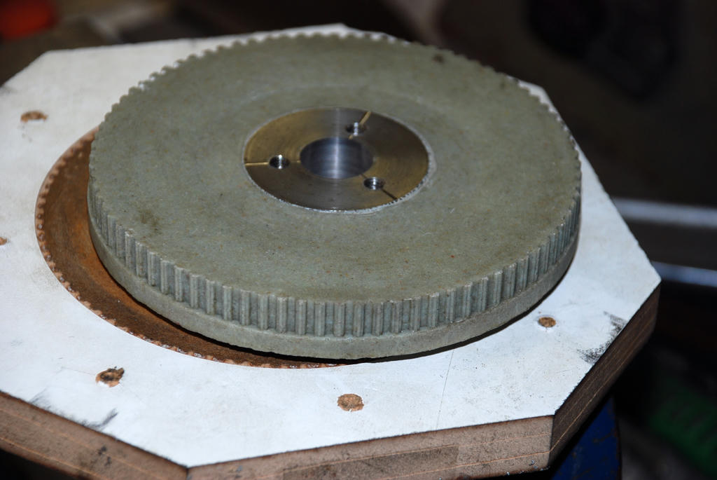
Stripping the mould was relatively easy. As usual it was damaged. MDF moulds have to be replaced each time. No problem it was just scrap. The most difficult part was the belt itself. Being polypropylene I knew it would not stick well to epoxy. That does not mean it does not stick at all. I had to gently place a small pin, I used a safety pin under each tooth to lift it clear of the epoxy; It took about 15 minutes to coax the belt off. As molded the pulley has one retaining lip edge molded in I may need to make another from steel depending on how the pulley is mounted. In this case the belt was in stock and it is only a test. For the next one I will make the retainer from steel sheet, place it in the mould before the belt and cast it in. For finishing it is quite easy to turn the epoxy sand mixture on the lathe. A carbide tip that is past its prime is fine, no need to blunt a new tip. As shown it has not been finished, it is “as is” from the mould. I did not add any colour to the mix so the colour is just the greenish sand epoxy colour. There are plenty of concrete colouring oxides (It must be the dry powder type not the liquid type) If you want a special colour. I rather like the colour as is. The result achieved so simply is outstanding. The tooth profile is a superb match for the belt. Cheers John McNamara Marking shaft mounting collar
Edited By John McNamara on 27/08/2011 17:47:46 Edited By John McNamara on 27/08/2011 18:12:41 |
| John McNamara | 27/08/2011 17:53:33 |
1377 forum posts 133 photos | Continued from previous post....
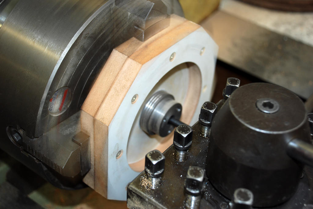
The base plate with collar attached was centred
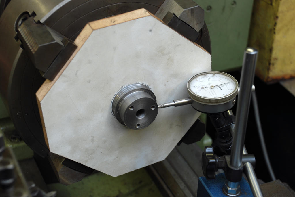 Edge plate prepared 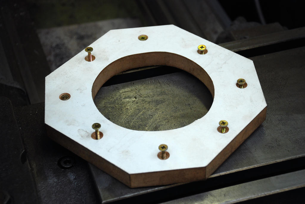 Fine boring the Mounting collar  The edge plate bored out and belt fitted inside 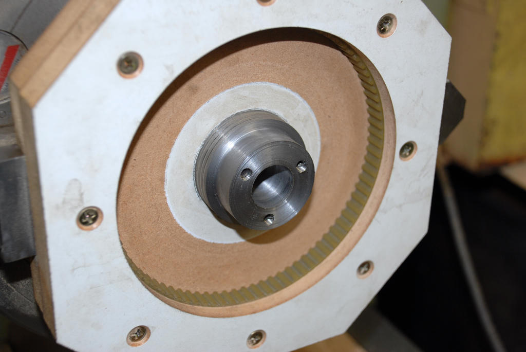 Poured! 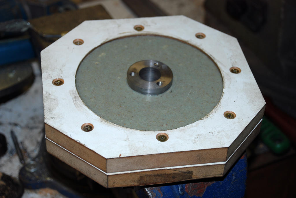 Collar attachment screws to be removed
 Edge plate removed 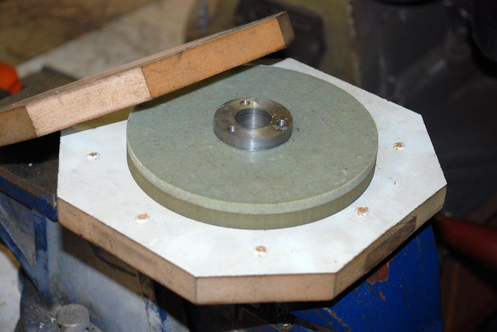 Removed from the backing plate 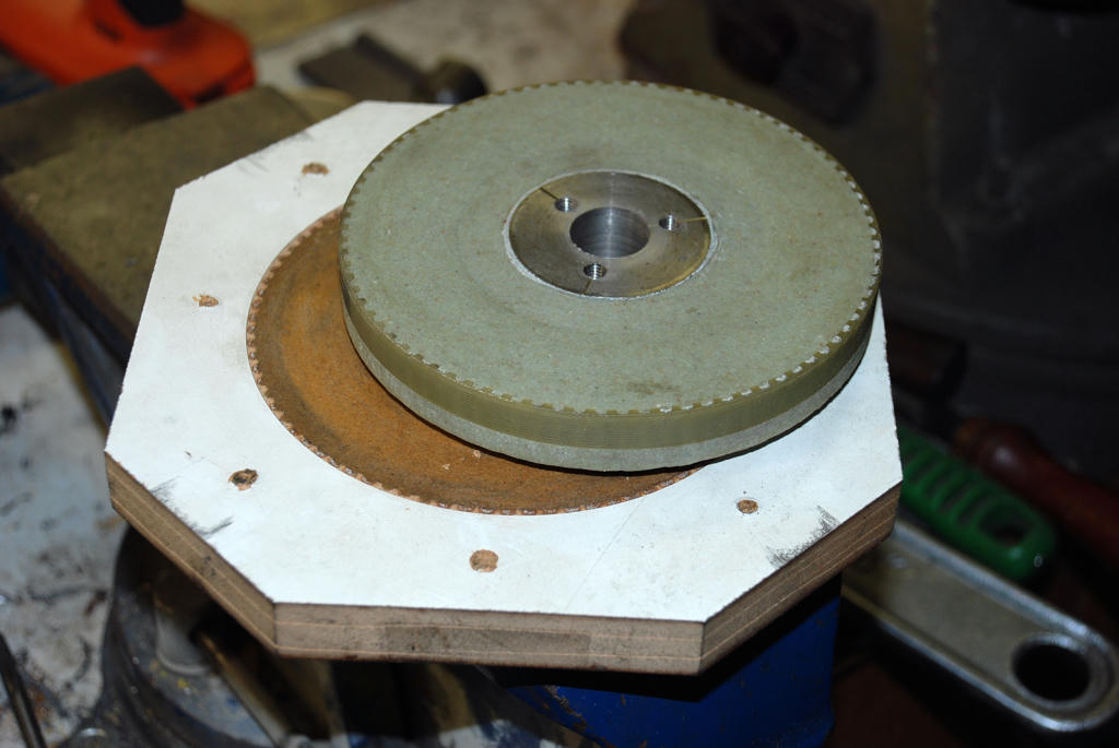 Belt removed....We have a timing pulley. Edited By John McNamara on 27/08/2011 18:05:51 |
| john swift 1 | 27/08/2011 21:25:57 |
 318 forum posts 183 photos | I like it , a simple solution without using a milling machine John Edited By john swift 1 on 27/08/2011 21:33:54 |
| Ian P | 27/08/2011 22:27:00 |
 2747 forum posts 123 photos | I like that!
It makes sense, straightforward to do, and as you say an economical way of making large pulleys.
One question, how did you ensure there were no air bubbles in the epoxy mix?
Another use for timing belts is to fit one on a mandrel (reversed, ie with the teeth facing outwards) and use it as a dividing plate if you need really unusual or prime numbers.
Ian |
| John McNamara | 27/08/2011 22:39:24 |
1377 forum posts 133 photos | Hi All
There is an error in the diameter calculations. Serves me right for being in a hurry. Luckily the bio computer still thought about it later.
I neglected to multiply by the tooth size
The number of teeth x the tooth size divided by PI equals the approximate diameter.
Cheers
John |
| John McNamara | 28/08/2011 07:13:07 |
1377 forum posts 133 photos | Hi all Errata: I should have said polyurethane not polypropylene regarding the belt material. Thank you D for pointing this out. With regard to vacuum degassing the mix to remove air bubbles yes it will help. I have avoided using this in my experiments because many small workshops will not have the facility. So all testing is done without it. I do have an acquired pump, wonderful word acquired….. but will have to make a chamber to place the material to be degassed in. For the larger CNC mill on the drawing board vacuum degassing the mix would be very difficult. Each mix will be around 20 litres that’s a fairly big chamber to evacuate. I hope to not use it. As you can see fairly clearly in the photographs; (Download this image from the link (DSC 5283) and zoom 100% for a better view) there is some small imperfections. I believe however they will not interfere with the performance of the pulley. I intend to make another sample next week using Aluminium powder instead of sand. This would no doubt increase the cost more than necessary if used for the entire cast portion of the pulley so I will only use it in the tooth area. For slow speed positioning applications I don’t think it will make much difference. I just don’t know what effect the sand grains might have at higher speeds. Maybe as part of a matrix with epoxy the sand will give superior wearing characteristics. Or maybe it will increase belt wear? The belts are made from very tough stuff. Cheers John Edited By John McNamara on 28/08/2011 07:42:29 |
| Michael Gilligan | 28/08/2011 09:32:58 |
 23121 forum posts 1360 photos | Excellent concept; and very nicely documented! Do please keep us updated regards your progress. One thought: ... I haven't checked the geometry but, for high tooth-counts it may be possible to simply use an inside-out belt as the teeth on a pulley. ... Ian P recommends this for "dividing", but it may also work for transmission. ... On the old trapezoidal profile, two flat lengths of belt [i.e. "Racks"] engage remarkably well. MichaelG. |
| John McNamara | 30/08/2011 02:50:30 |
1377 forum posts 133 photos | Hi All Thank you for the encouraging words. A mate is coming over soon to discuss a large clock, on a building. By using large gears the necessary reduction can be done in two stages with the largest gear being about 300mm diameter. This will be a good real life test. As far as reversing the belt to make a pulley it does not work, the geometry even at large diameter’s stops it. You could use a reversed belt as a gear if you made a special mating pinion however the tooth load would have to be low because you would only have about one tooth engaged. One thought that came to mind for an indexing table would be to use a belt or a cast gear with a matching cast “Segment”, I had a play with the test pulley and belt. The test pulley has 120 teeth I found that you can lift off a section of the belt well over a quarter of the diameter of the gear. (The stopping point is when the angle of the tooth side faces reaches the point of undercut) Does anyone want to develop a formula for this? Anyway empirical methods will do for the time being! And getting back to an indexing table concept, the (Cast in filled Epoxy) segment would allow in this case about 30 teeth engaged. If the segment were attached to a table locking mechanism, possibly a pivoting arm or a slide, an extremely rigid connection would result; capable of taking any likely cutting load. After disengaging the lock the table can be indexed one or more teeth at a time. With the accuracy improvement, a benefit of multiple teeth engaging averaging any errors, similar to a “curvic coupling” Does anyone want to make one ? Cheers John Edited By John McNamara on 30/08/2011 02:57:03 |
| John McNamara | 30/08/2011 03:35:32 |
1377 forum posts 133 photos | Hi All
The tooth angle is 40 degrees included.
Cheers
John
|
| John McNamara | 30/08/2011 04:46:42 |
1377 forum posts 133 photos | Hi All
A quick investigation of the cast index lock using CAD revealed that the correct angle is 40 degrees. That makes sense. I drew a design using 44 degrees as the undercut angle on the end teeth is very small and that gave an extra tooth. If there is too much interference that tooth can be filed down. As shown 15 teeth are engaged with the 120 tooth wheel as cast in the first post, maybe that will end up 14 teeth. In both cases a good result. It will create an extremely strong, and very accurate positioning lock. The drawing does not show it but I think the segment should be steel backed with a cast in place reinforced filled epoxy face. The same method can be used with a steel gear.
Cheers John 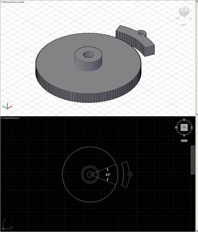 Edited By John McNamara on 30/08/2011 04:55:58 |
| Michael Gilligan | 30/08/2011 08:20:00 |
23121 forum posts 1360 photos | John, That locking arrangement looks very neat; and potentially very useful. The datasheet for T5 belt is also handy to have on file, thanks. MichaelG. Footnote: There is some very useful info available from Gates http://www.gates.com/catalogs/index.cfm?requesting=ptcatalog&location_id=524 ... it's especially worth looking at the "Interchange Guide". Edited By Michael Gilligan on 30/08/2011 08:50:42 |
Please login to post a reply.
Magazine Locator
Want the latest issue of Model Engineer or Model Engineers' Workshop? Use our magazine locator links to find your nearest stockist!
Sign up to our Newsletter
Sign up to our newsletter and get a free digital issue.
You can unsubscribe at anytime. View our privacy policy at www.mortons.co.uk/privacy
Latest Forum Posts
- *Oct 2023: FORUM MIGRATION TIMELINE*
05/10/2023 07:57:11 - Making ER11 collet chuck
05/10/2023 07:56:24 - What did you do today? 2023
05/10/2023 07:25:01 - Orrery
05/10/2023 06:00:41 - Wera hand-tools
05/10/2023 05:47:07 - New member
05/10/2023 04:40:11 - Problems with external pot on at1 vfd
05/10/2023 00:06:32 - Drain plug
04/10/2023 23:36:17 - digi phase converter for 10 machines.....
04/10/2023 23:13:48 - Winter Storage Of Locomotives
04/10/2023 21:02:11 - More Latest Posts...
- View All Topics
Support Our Partners


Shopping Partners
Subscription Offer

Latest "For Sale" Ads
- Reeves** - Rebuilt Royal Scot by Martin Evans
by John Broughton
£300.00 - BRITANNIA 5" GAUGE James Perrier
by Jon Seabright 1
£2,500.00 - Drill Grinder - for restoration
by Nigel Graham 2
£0.00 - WARCO WM18 MILLING MACHINE
by Alex Chudley
£1,200.00 - MYFORD SUPER 7 LATHE
by Alex Chudley
£2,000.00 - More "For Sale" Ads...
Latest "Wanted" Ads
- D1-3 backplate
by Michael Horley
Price Not Specified - fixed steady for a Colchester bantam mark1 800
by George Jervis
Price Not Specified - lbsc pansy
by JACK SIDEBOTHAM
Price Not Specified - Pratt Burnerd multifit chuck key.
by Tim Riome
Price Not Specified - BANDSAW BLADE WELDER
by HUGH
Price Not Specified - More "Wanted" Ads...
Get In Touch!
Do you want to contact the Model Engineer and Model Engineers' Workshop team?
You can contact us by phone, mail or email about the magazines including becoming a contributor, submitting reader's letters or making queries about articles. You can also get in touch about this website, advertising or other general issues.
Click THIS LINK for full contact details.
For subscription issues please see THIS LINK.
Digital Back Issues


Donate

 Register
 Log-in
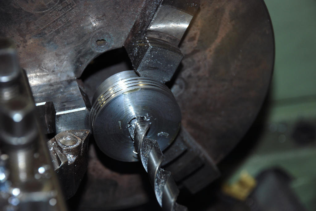
Model Engineer Magazine
- Percival Marshall
- M.E. History
- LittleLEC
- M.E. Clock

ME Workshop
- An Adcock
- & Shipley
- Horizontal
- Mill

Subscribe Now
- Great savings
- Delivered to your door

Pre-order your copy!
- Delivered to your doorstep!
- Free UK delivery!
All Forum Topics > Model Engineers' Workshop. > Make your own timing pulleys