Forum sponsored by:

Something to ponder 02
| Martin W | 11/07/2011 10:08:40 |
| 940 forum posts 30 photos | Michael
From your post I assume that the microscope is already fitted with a manually operated X Y table/stage that is to be converted to a motor driven system and this is not a project to design a complete table and drive that will be fitted to an existing microscope?
Secondly do you want absolute or relative positioning or just a method to drive the table to any position effectively under manual control? The final design will be dependant on the initial requirement specified.
Cheers
Martin |
| Steve Garnett | 11/07/2011 11:45:02 |
| 837 forum posts 27 photos | As Martin has clearly realised, the first thing you have to do as a system engineer in this situation is fully understand the problem... In general though, these situations require mechanisms that have minimal stiction. If I was starting from scratch with a relatively small table, I think I'd be looking at a differentially powered air-supported system, and one of the critical things about it is how you're going to get suitable feedback from the positioning system to enable sub-micron accuracy. Since the movement is essentially to be viewed, I think I'd at least initially be looking at using the imaging system to increase the effective resolution of the feedback. Ultimately, the best form of control would be to use a three-term feedback system on both axes, because that would keep everything under control. An interesting challenge though will be to provide an adequate position sensor, I suspect - and that one I don't have an immediate answer to! |
| ady | 11/07/2011 11:50:41 |
| 612 forum posts 50 photos | As a complete boo-boo I would look at a detachable worm drive system because of its ability to gear down to very small increments, its speed over the larger angles/distances, and its relative simplicity. As a practical example I would look at the system they use on a sextant and adapt it for my particular project. You could always add on an electronic control system of servos. As an extreme example of measurement even back in the 1900s they knew that venus was something like 14 inches "out" from where it actually should be when using newtons laws, but I've never researched the equipment they used. This was what gave them the clues, but not the answers to relativity, until einsteins theory during WW1. Edited By ady on 11/07/2011 12:02:17 |
| Martin W | 11/07/2011 15:26:18 |
| 940 forum posts 30 photos | Hi
Systems to achieve fine movement without incremental steps are used in fine focus mechanisms of microscopes. One of these as used in some Biolam units use a step down gear train the with the final drive operating a push rod, via a relatively large crank, which presses against the body of the stage. The stage is spring loaded against this push rod to take out any back lash and the movement of the crank is limited so as to minimise errors that occur using this method. The hand/thumb wheel that drives this arrangement is calibrated in 2 micron intervals which can easily be read to 1 micron. Put a suitable rotary encoder on this shaft and in theory sub micron resolution is possible with good repeatability.
Another system used for fine focus which may have merit for stage movement is that using a tapered spindle. This is again acting against a spring loaded loaded assembly to reduce backlash. The taper is either advanced or retracted by means of a screw with or without gear a box. The driven assembly then moves and reproduces the form of the taper. In the case of the fine focus the taper profile is linear and again it is easy to resolve intervals to 1 micron manually.
Both the above solutions only offer a limited movement in the range of 1 - 2mm max. Therefore if one is to drive a microscope stage over the full area of a standard cover slip, assuming 3 x 1 inch slides, then another system will be required for coarse positioning; this term is relative because the final position of this system must still be accurate.
Cheers
Martin Edited By Martin W on 11/07/2011 15:39:40 |
| Martin W | 11/07/2011 15:54:31 |
| 940 forum posts 30 photos | An After Thought
 I wonder whether there is mileage in using a micrometer barrel assembly. This gives rotary drive system, suitable for a rotary encoder, with the benefits of an adjuster to minimise backlash at a low cost plus it will traverse about 25mm which should be enough and is relatively compact. Drive systems would be relatively easy to design with the only the zero point on both axis needing to be calibrated prior to each power up. This could easily be achieved using an optical switch and then seeking the next zero on the encoder as the start point.
Simples eh
Regards
Martin Edited By Martin W on 11/07/2011 15:56:56 |
| John McNamara | 11/07/2011 16:17:11 |
 1377 forum posts 133 photos | Hi Michael Williams.
From yiour post:
"If any of you were presented with the task of designing a positioning system for a microscope table with X Y positioning , very smooth action and sub micron accuracy how would you do it ?? "
1/1000 of a milimetre is a very small number = 1/254000 of an inch Or .00003937007874015748 inches I would start by looking at the materials to be used and the environment that the device will operate in For example if the device were to be made in steel Calculations in inches The coefficient of linear expansion for steel 0.0000072 inches per degree Fahrenheit What if? The measuring stage has structural members say 100 mm long (4 inches) And the temperature of the room where the device was located changed by 5 degrees F. What effect would it have on the structure? 0.0000072 X5 (Degrees) .000036 X4 (Inches) .000144 (inches expansion for the structural member) That is over a ten thousandth of an inch measurement error due to temperature change. The difficulty being we looking for better than a 1/254000 inch A 5 degrees F temperature is less than the average daily fluctuation. Using Aluminium is definitely out... the expansion being far greater Glass and porcelain are a lot better (Pyrex being 2.2*10^-6 Deg f compared to steel 7.3 *10^-6 Deg f) See Table link below. Making the stage as small as possible will help reduce the total error Maybe the application does not need to have (repeatable) measurement of length compared to an international standard.
The best book I know that will assist solving this problem. It lists in great detail the various methods of measurement and the construction of machines with micron accuracy. It is not inexpensive but there is none better to my knowledge. It should be available on inter library loan.
Table of contents:
Surface measuring stage: (Referred to in Slocum book)
A useful table:
Design example of ultra precision machines, interesting paper. A slow but free download .
(National Institute of Science and Technology) Some also designed by Slocum.
Cheers
John
Edited By John McNamara on 11/07/2011 16:22:32 Edited By John McNamara on 11/07/2011 16:31:42 Edited By Katy Purvis on 01/06/2015 11:42:36 |
| Martin W | 11/07/2011 17:12:21 |
| 940 forum posts 30 photos | Hi
Of course there are further parameters that must be established. A light microscope has limited resolution due to the wavelength of light although by using different techniques, such as phase contrast, finer and low contrast detail can be resolved to a degree. After that it is into the world of electron microscopes where the environment is totally different.
So horses for course as they say and if real accuracy is required then temperature stabilisation etc is a real necessity as indicated by John in his post.
Cheers
Martin |
| John Haine | 11/07/2011 17:55:20 |
| 5563 forum posts 322 photos | My father used to work for a company making electron microscopes. Their stage positioning systems use a "differential screw". This might have a thimble arrangement like a micrometer with say a 1 mm pitch thread; whilst the shaft itself has a thread of say 0.99 mm pitch turned on it. This in turn fits in a threaded collar that is on the end of the pushrod. When you turn the thimble 1 turn it advances by 1 mm, but the collar is pulled back 0.99 mm - result is an effective pitch of 0.01 mm, 10 microns. Everything spring loaded to remove backlash. |
| Andrew Johnston | 11/07/2011 19:52:18 |
 7061 forum posts 719 photos | The first thing to do is determine a proper specification.  Regards, Andrew |
| John McNamara | 12/07/2011 00:34:06 |
1377 forum posts 133 photos | Hi All
Ther is an error In my post above I mention a micron as 1/254000. The decimal point devel got me
 A micron is 1/1000 of a millimetre.
Clearly it should read 1/25400
It does not however change the need to consider temperature. To work accurately in microns is indeed an art.
Cheers
John |
| Steve Garnett | 12/07/2011 10:57:37 |
| 837 forum posts 27 photos | Expansion/contraction is only an issue as far as the table itself is concerned - it won't make any difference to viewing. If the feedback mechanism is referenced directly from the table, then this will also expand and contract with it. This means that positionally, it's stable - but that as a measurement system, it will have a thermal error, unless the table is compensated somehow. So I still agree with Martin, and now Andrew - specification needed! Quite an interesting exercise to consider different ways of doing it, though. Whilst it would be interesting to see if there was a practical way of doing it within one discipline, I rather suspect that a pragmatic solution won't come about that way. |
| John McNamara | 13/07/2011 06:54:35 |
1377 forum posts 133 photos | Hi Michael Williams
I stumbled on this site. trade brochure Here:
Maybe it will assist in your design process.
Cheers
John |
| Martin W | 13/07/2011 10:43:52 |
| 940 forum posts 30 photos | Hi MichaelG
Is the stage you bought one of those that utilises ball bearings running between hardened steel wire guides to form the linear slide bearings? I think I remember Nikon or some manufacturer using this method as it gave very accurate tracking with very low friction. I must admit I envy you your acquisition
 . .Best regards
Martin |
| Richard Parsons | 13/07/2011 11:28:45 |
 645 forum posts 33 photos | Do you mean something like the drawing. I am working on them to use on a small planer I want to build. The original I want to use as the stage on a micro drill (if ever I can get a picture of the mechanism of the Boley model 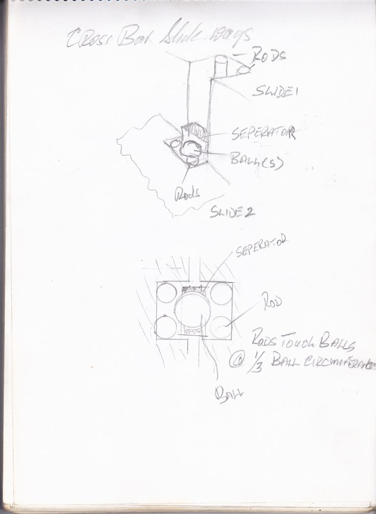 |
| Richard Parsons | 13/07/2011 16:00:53 |
645 forum posts 33 photos | MikeG Yes I know about the gib. I am only going to use this type of slide way if I can get the necessary rod/wire and channel. As to the problems of swarf that is the least of my problems. I plan that the ‘balls’ will contact the wires at 1/3 of the balls circumference. Does this sound too wide a contact angle? I will be using channel because I am going to build the rest using Epoxy-concrete mixture Rdgs Dick |
| Michael Gilligan | 13/07/2011 19:29:50 |
 23121 forum posts 1360 photos | Dick, Could I just mention that I much prefer to be called Michael. With that off my chest ... 1/3 of the ball circufrence sounds quite reasonable to me. I'm delighted to hear that you are using Epoxy-concrete; it's something I have wanted to try for years, but never got around to. There was a lot of good work done at Cranfield in the late 1970s / early 80s. ... If you haven't already done so; try a Google search for Granitan. Please let me know how the build goes. MichaelG. |
| alan frost | 14/07/2011 09:42:25 |
| 137 forum posts 3 photos | Not an area I have any expertise in at all , but is there no possibility of using suitable Piezo-electrics for very small ,accurate, well-defined motion. I vaguely remember reading something on it years ago. Any experts in this technique ???? |
| Pat | 14/07/2011 10:40:57 |
| 94 forum posts 1 photos |
The problem with microscope sub stages manipulation is one of vibration. As most if not all microscope use is under stable temperature condition the effect of thermal expansion during can usually be ignored provided the mechanism has the ability to absorb large changes in the design of the slides and other moving parts. Some stages have to operate under vacuum as well as at various temperatures as part of the observations of the specimen.
Cam and lever with a small electric motor are the normal methods of motion control. The speed of traverse is normally very slow as the field of view is restricted so it is all too easy to loose the subject if the movement is too rapid. A large reduction in the gearing between the motor and the cam is often provided by a double or triple sun an planet coaxial gear box as part of the motor drive. The lever and cam mechanism being arranged to provide quick initial centring of the specimen.
On optical quality mechanisms it is often a good idea to use a very viscous grease specially formulated for this type of use. This gives a nice action by damping the vibration as the parts move. Unfortunately the use of vacuum often precludes the use of lubricants necessitating dry film and/or sintered bearing surfaces with external to the vacuum chamber motors etc.
The use of motive forces that involve impulses require that the impulse is applied as a balanced force to avoid vibration which is the bugbear of the high power microscope.
The use of pneumatic / hydraulic manipulators is common to isolate the manipulating tool from the operator. These mechanisms use the operator in the feedback loop OR have some very sophisticated means of providing tool point position for feedback in the servo loop.
Hope this helps - Regards - Pat
PS Yet again define the total movement - the accuracy of placement - speed of movement - any rapid movement requirement - environmental conditions as vacuum and temperature are often critical to microscope stages. Contamination issues also arise which may require special attention as parts may need to be removed for sterilisation in some nasty fluids.
PSS The use of a piezo material as a beam that can be deflected using an applied voltage is well known but has very limited movement and would need to be part of a dual stage motion in a practical implementation unless the specimen is pre located by other means. The use of other materials might be more amenable to experimentation as a DIY project two materials come to mind electroactive polymers and memory alloy. The latter is available in short lengths and is used for nano bots and toys but the movement is small and there are hysteresis effects to be accommodated. Edited By Pat on 14/07/2011 11:10:15 |
| Michael Gilligan | 14/07/2011 12:34:52 |
23121 forum posts 1360 photos | Alan Frost, Yes, Piezo drives are used for very high precision stages; but these typically also have short travel. ... Those in the catalogue that John McNamara found being fairly representative. I don't know what stage travel Michael Williams has in mind. Piezo drive is certainly worth further investigation though. MichaelG. |
| Richard Parsons | 14/07/2011 14:06:07 |
645 forum posts 33 photos | Michael Sorry about that. I just cut and pasted the name on your post. Actually has a look at this thread ‘New technology in Model Engineers Workshop’ it is a long thread. I am thinking of using the techniques as metal over here in Hungary is very difficult to get, but I have a large garden full of the most wonderful sand. I want to build a planer. It’s size will depend on the materials I can get. If I have to use the classic machines slide ways I am limited to about 16” (406mm) with a table of about 7” (178mm). If I can get 3-4mm hardened rods and can find or make suitable channel steel I will build a 24” (610mm) long machine with a 10” (254mm) table. At the moment I am trying to calculate what and where the stresses are on the guide ways. It all depends on getting everything I need locked away before I start. By ‘locked away I mean ‘locked’! |
Please login to post a reply.
Magazine Locator
Want the latest issue of Model Engineer or Model Engineers' Workshop? Use our magazine locator links to find your nearest stockist!
Sign up to our Newsletter
Sign up to our newsletter and get a free digital issue.
You can unsubscribe at anytime. View our privacy policy at www.mortons.co.uk/privacy
Latest Forum Posts
- *Oct 2023: FORUM MIGRATION TIMELINE*
05/10/2023 07:57:11 - Making ER11 collet chuck
05/10/2023 07:56:24 - What did you do today? 2023
05/10/2023 07:25:01 - Orrery
05/10/2023 06:00:41 - Wera hand-tools
05/10/2023 05:47:07 - New member
05/10/2023 04:40:11 - Problems with external pot on at1 vfd
05/10/2023 00:06:32 - Drain plug
04/10/2023 23:36:17 - digi phase converter for 10 machines.....
04/10/2023 23:13:48 - Winter Storage Of Locomotives
04/10/2023 21:02:11 - More Latest Posts...
- View All Topics
Support Our Partners


Shopping Partners
Subscription Offer

Latest "For Sale" Ads
- Reeves** - Rebuilt Royal Scot by Martin Evans
by John Broughton
£300.00 - BRITANNIA 5" GAUGE James Perrier
by Jon Seabright 1
£2,500.00 - Drill Grinder - for restoration
by Nigel Graham 2
£0.00 - WARCO WM18 MILLING MACHINE
by Alex Chudley
£1,200.00 - MYFORD SUPER 7 LATHE
by Alex Chudley
£2,000.00 - More "For Sale" Ads...
Latest "Wanted" Ads
- D1-3 backplate
by Michael Horley
Price Not Specified - fixed steady for a Colchester bantam mark1 800
by George Jervis
Price Not Specified - lbsc pansy
by JACK SIDEBOTHAM
Price Not Specified - Pratt Burnerd multifit chuck key.
by Tim Riome
Price Not Specified - BANDSAW BLADE WELDER
by HUGH
Price Not Specified - More "Wanted" Ads...
Get In Touch!
Do you want to contact the Model Engineer and Model Engineers' Workshop team?
You can contact us by phone, mail or email about the magazines including becoming a contributor, submitting reader's letters or making queries about articles. You can also get in touch about this website, advertising or other general issues.
Click THIS LINK for full contact details.
For subscription issues please see THIS LINK.
Digital Back Issues


Donate

 Register
 Log-in
Model Engineer Magazine
- Percival Marshall
- M.E. History
- LittleLEC
- M.E. Clock

ME Workshop
- An Adcock
- & Shipley
- Horizontal
- Mill

Subscribe Now
- Great savings
- Delivered to your door

Pre-order your copy!
- Delivered to your doorstep!
- Free UK delivery!
All Forum Topics > General Questions > Something to ponder 02