Forum sponsored by:

CNC XY Table for clock making no Z axis
| Stephen Benson | 18/05/2011 20:15:14 |
 203 forum posts 69 photos |
I have been wanting to make a robust CNC XY table to fit on top of my mill table with a 150x120mm or so area for making parts for clocks in up to 1/4 brass sheet. The Z axis would be manual using the mills own spindle.
I would want this for short production runs of several hours and for it to be accurate to about 0.10mm so I could be in commercial machine territory but I have no room and maintenance costs scare me. I do not want to reinvent the wheel but I have not seen any plans that fit the bill anybody got any ideas?
Edited By Stephen Benson on 18/05/2011 20:15:55 Edited By Stephen Benson on 18/05/2011 20:16:37 |
| Tony Jeffree | 18/05/2011 23:00:23 |
 569 forum posts 20 photos | There are plenty of X-Y tables around, available from the usual suspects. For example, Arc Eurotrade (catalogue distributed with this month's MEW) has 3 sizes of table on page 43 of the catalogue; he smallest has a table 200mmX90mm and a table travel of 130mmX70mm. These are manual tables, but would be simple enough to convert to stepper drive if you so desired, using the existing leadscrews. Regards, Tony |
| John Stevenson | 18/05/2011 23:16:08 |
 5068 forum posts 3 photos | Arc has an example of the small table converted to stepper drive with two of the tiny type 16 motors fitted. I did this about two years ago as an exercise and it was just a bolt on, no modifications were made to the table at all. 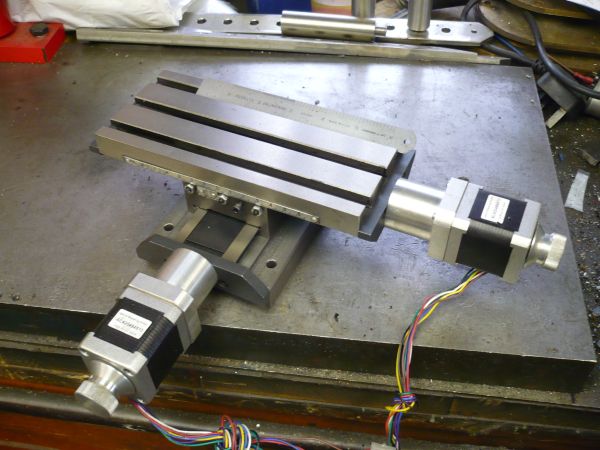 Image dated July 2nd 2010 John S. Edited By John Stevenson on 18/05/2011 23:16:32 |
| Stephen Benson | 19/05/2011 08:42:03 |
203 forum posts 69 photos | Thanks for the replys but is using a manual machine table the way to go, I would of thought that it was a huge compromise due to the backlash, weight and drag issues.
What I had in mind was a ball bearing lead screw with linear bearings to hold may be 8-10mm thick flat aluminium table sorry for the misunderstanding.
But if converting a manual machine is considered the correct way to go how do you over come the above problems.
|
| Tony Jeffree | 19/05/2011 12:04:19 |
569 forum posts 20 photos | Posted by Stephen Benson on 19/05/2011 08:42:03: Thanks for the replys but is using a manual machine table the way to go, I would of thought that it was a huge compromise due to the backlash, weight and drag issues. What I had in mind was a ball bearing lead screw with linear bearings to hold may be 8-10mm thick flat aluminium table sorry for the misunderstanding. But if converting a manual machine is considered the correct way to go how do you over come the above problems. Whatever way you go, there are compromises - your proposed direction of linear bearings and aluminium table will be a compromise on stiffness compared with a starting point of a cast iron X-Y table, for example. Also, while ballscrews have advantages (low rate of wear and low friction, for example) eliminating backlash isn't necessarily one of them, unless you pay more for anti-backlash nuts. There are ways of reducing backlash in conventional screws, and often a significant part of the backlash can be eliminated by fitting decent bearings on the leadscrews, especially if the original ones were plain bearings. Regards, Tony |
| Stephen Benson | 19/05/2011 17:15:34 |
203 forum posts 69 photos | I have been using industrial CNC machines most my working life and the two runner with centre ball screw model seems to be common to most the industrial machines I have experienced so I suppose I expected to see it in the hobby machines as well. Certainly I do not see stiffness to be an issue as stiffness is more about design rather than mass especially in the small table size (150x120mm) I propose. |
| Tony Jeffree | 19/05/2011 22:33:43 |
569 forum posts 20 photos | Posted by Stephen Benson on 19/05/2011 17:15:34: I have been using industrial CNC machines most my working life and the two runner with centre ball screw model seems to be common to most the industrial machines I have experienced so I suppose I expected to see it in the hobby machines as well. Certainly I do not see stiffness to be an issue as stiffness is more about design rather than mass especially in the small table size (150x120mm) I propose. OK...but why go to the bother when you can start from a ready-made X-Y table? Regards, Tony |
| Pat | 20/05/2011 12:19:31 |
| 94 forum posts 1 photos | Hi Stephen Can we assume that 0.10mm means that you are looking to maintain positional accuracy across the table envelope of + to - 0.005 mm or better? The problem of part interchangeability and co-ordinate tolerance needs to be factored into any production run unless you are prepared for selective assembly of parts and some scrap parts. You will need to think very carefully about the above tolerance requirements as you could quite easily get into the area of servos that use linear scales as feed back elements. This would vastly increase the cost of the table. For clock making the co-ordinate tolerances are relatively relaxed as the gear centers are run with a very loose mesh as the need is for minimal friction. Backlash in the gearing is not an issue also the speeds are very low so noise produced by a loose mesh is not relevant. Clock makers also use gear tooth forms that are designed for minimal friction unlike engineering tooth forms that are designed to provide smooth rotational transmission of torque, low back-lash and quiet running. Make a clock with this sort of gearing and it will require too much power to be viable. The simple table pointed out by John Stevenson would probably achieve all that you need for both clock plates and gear wheels. The actual weight of that table would help with getting the required fine finish on the gear tooth profile with out too much polishing. The backlash is simply controlled by approaching any critical dimension from the same direction each time. Easy to do the CNC as it will repeat the direction each and every time in stead of getting fed up with the extra handle twirling! There would remain the problem of lead screw wear and this is one reason to convert to ball-screw drive. The dove-tail wear should be relatively low provided you use a lubricant that is designed for slide-ways. This oil is a specialty oil designed for minimal stick slip and the constant reversal in direction of travel. If the production run is long then the linear bearing skates and matching rails would be required. These are expensive and result in a loss of usable 'Z' axis travel. The round rod type of linear slides unless very carefully designed could give you rigidity issues due to the construction of the insert bearing. Suggest you fix the co-ordinate tolerance you need then look at the accuracy obtainable from the various table axis drives then look at how much each design costs. Then revise to get a good working solution. I would go for the simple table with dove-tail slides and stepper motors as I think this will give you the repeatability required for clock making. Convert to ball-screw if the lead screws wear out and modify the CNC tool paths so that each critical dimension is approached from the same direction each time. Hope this helps to get you cutting brass - Regards - Pat Edited By Pat on 20/05/2011 12:24:03 |
| Pat | 20/05/2011 13:55:51 |
| 94 forum posts 1 photos | Hi Stephen To give you and idea on pricing you may care to look at this site:- http://www.slidesandballscrews.com/hgr25-profile-rail-p-404.html?cPath=40_120_122 Zapp Automation is a source of precision linear slides and trucks by Hinwin. Cost is around £600 for 400mm ways and eight trucks. They also have the servos but think in terms of £300 for the DRO and another £500 plus for two servos and £300 for ball screws and B12 bearings. They also do the cheaper linear ball bearing type but these are more appropriate for a light weight mechanism. If you reduce the feed rates tool pressure you might be able to use the light weight liner round rail but the accuracy will be difficult to determine as information of the rigidity is difficult to come by as these bearings are not intended for the precision table application. Regards - Pat |
| Stephen Benson | 20/05/2011 18:40:09 |
203 forum posts 69 photos |
Thanks everybody some really great information and I am very grateful I am almost convinced but I have a serous paradigm to break but I suppose I have not lost too much if I have to upgrade the table at some point.
So John if you could give a little more info on your table conversion I would be very grateful.
Cheers Steve
|
Please login to post a reply.
Magazine Locator
Want the latest issue of Model Engineer or Model Engineers' Workshop? Use our magazine locator links to find your nearest stockist!
Sign up to our Newsletter
Sign up to our newsletter and get a free digital issue.
You can unsubscribe at anytime. View our privacy policy at www.mortons.co.uk/privacy
Latest Forum Posts
- *Oct 2023: FORUM MIGRATION TIMELINE*
05/10/2023 07:57:11 - Making ER11 collet chuck
05/10/2023 07:56:24 - What did you do today? 2023
05/10/2023 07:25:01 - Orrery
05/10/2023 06:00:41 - Wera hand-tools
05/10/2023 05:47:07 - New member
05/10/2023 04:40:11 - Problems with external pot on at1 vfd
05/10/2023 00:06:32 - Drain plug
04/10/2023 23:36:17 - digi phase converter for 10 machines.....
04/10/2023 23:13:48 - Winter Storage Of Locomotives
04/10/2023 21:02:11 - More Latest Posts...
- View All Topics
Support Our Partners


Shopping Partners
Subscription Offer

Latest "For Sale" Ads
- Reeves** - Rebuilt Royal Scot by Martin Evans
by John Broughton
£300.00 - BRITANNIA 5" GAUGE James Perrier
by Jon Seabright 1
£2,500.00 - Drill Grinder - for restoration
by Nigel Graham 2
£0.00 - WARCO WM18 MILLING MACHINE
by Alex Chudley
£1,200.00 - MYFORD SUPER 7 LATHE
by Alex Chudley
£2,000.00 - More "For Sale" Ads...
Latest "Wanted" Ads
- D1-3 backplate
by Michael Horley
Price Not Specified - fixed steady for a Colchester bantam mark1 800
by George Jervis
Price Not Specified - lbsc pansy
by JACK SIDEBOTHAM
Price Not Specified - Pratt Burnerd multifit chuck key.
by Tim Riome
Price Not Specified - BANDSAW BLADE WELDER
by HUGH
Price Not Specified - More "Wanted" Ads...
Get In Touch!
Do you want to contact the Model Engineer and Model Engineers' Workshop team?
You can contact us by phone, mail or email about the magazines including becoming a contributor, submitting reader's letters or making queries about articles. You can also get in touch about this website, advertising or other general issues.
Click THIS LINK for full contact details.
For subscription issues please see THIS LINK.
Digital Back Issues


Donate

 Register
 Log-in
Model Engineer Magazine
- Percival Marshall
- M.E. History
- LittleLEC
- M.E. Clock

ME Workshop
- An Adcock
- & Shipley
- Horizontal
- Mill

Subscribe Now
- Great savings
- Delivered to your door

Pre-order your copy!
- Delivered to your doorstep!
- Free UK delivery!
All Forum Topics > CNC machines, Home builds, Conversions, ELS, automation, software, etc tools > CNC XY Table for clock making no Z axis