Forum sponsored by:

Perfecto shaper
| Cornish Jack | 14/12/2009 19:21:32 |
| 1228 forum posts 172 photos | G'day all I'm looking for any hints, tips, general or specific info on the Perfecto (powered) shaper. I have used a much larger version, years ago. in an evening class workshop but the Perfecto doesn't quite fit into that category!! An additional, unrelated query - I wish to fit a reversing switch to a Worden grinder motor. The Worden build notes give good detail on the motor mods required and I now have a five core cable to wire it up. However the switch (Kraus and Naimer) wiring diagram is (to my untutored eyes) obscure - to say the least.!! My 'wiggly amps' expertise runs to standard 3 pin plugs with Live/ Neutral/ Earth annotations. The 'Connecting diagrams' for this switch offer six different versions (none for this model, specifically) and with connections marked, variously as L!, L2 , L3 and N. Is there a simple translation for these markings, please? TIA Bill |
| Les Jones 1 | 14/12/2009 20:11:41 |
| 2292 forum posts 159 photos | Hi Bill, I think you will need to attach the information on the motor and the switch to your next post for anyone to be able to help you with the motor problem. Les. |
| mgj | 14/12/2009 21:13:49 |
| 1017 forum posts 14 photos | Those connections are numbered for 3 phase! (Live 1,2,3 and a Neutral.) Somewhere in the book of words will be a wiring diagram to wire the switch for single phase and to reverse the connections to the capacitor. Look for a diagram that has Z and AZ which are the capacitor connections and should tally with the motor, and that will be the one you need. I assume you are connecting single phase. Edited By meyrick griffith-jones on 14/12/2009 21:15:08 Edited By meyrick griffith-jones on 14/12/2009 21:16:40 |
| Martin Cottrell | 14/12/2009 21:39:27 |
| 297 forum posts 18 photos | Hi Bill,
I have recently wired up the motor and reversing switch for my Worden following the instructions and wiring diagram without any problems although I seem to remember having to identify the start and running winding terminals with an ohmmeter as per the instructions first. Once I had identified the two separate winding connections the wiring diagram made sense! However, I was using the motor and switch as supplied in the Hemingway kit, from the tone of your post it would seem that you may be using different components?
As Les has said above, it would be a good idea if you could give some more information on the switch and motor, in particular the annotation on the terminals as these can vary according to the Hemingway literature, (hence the need to identify the separate windings with an ohmmeter).
Regards, Martin. |
| Cornish Jack | 14/12/2009 21:44:04 |
| 1228 forum posts 172 photos | Thank you Les and Meyrick. Yes, single phase it is and three phase is witchcraft as far as I'm concerned!! L1,L2 and L3 should have been obvious as 3 phase, in hindsight. Unfortunately there is no 'book of words', just some 20 plus diagrams which give connections for all sorts of uses and various models but none of the motor connections are for this particular switch model number. Methinks it's back to the seller for more info. |
| Cornish Jack | 14/12/2009 21:48:54 |
| 1228 forum posts 172 photos | Thank you Martin. Yes, correct - the original switch has 'gone walkabout' so I had to get a replacement - hence the problem. If all else fails I may have to go back to hemingway to look for a proper replacement. I bought the kit in '95 and have only just got around to completing it (or trying to!!  |
| Les Jones 1 | 14/12/2009 22:21:26 |
| 2292 forum posts 159 photos | Hi Bill, The diagrams are what you need to attach to your post. (Or the exact model number of the switch so the person helping can look at these diagrams on the manufacturers website.) Is the switch a three position switch of the style forward, stop, reverse or is it just a two position switch that will be used in conjunction with a separate on / off switch ? There must be more than the four connections you mentioned (L1, L2. L3 and N) I suspect that there will be 12 connections (But there may only be 8) If you cannot attach these diagrams can you meter out the continuity between all the connections of the switch in its three (or two) positions to create a "truth table" for the switch. I tried to look for the data on the motor on the Hemingway website bit it is only available by buying the book. Does the motor have an up to speed switch which disconnects the start winding when the motor is up to speed or is the start winding connected all the time via the start capacitor ? (This would be clear if you could attach the wiring diagram of the motor with the reversing switch supplied by Hemingway.) Les. |
| mgj | 14/12/2009 23:27:53 |
| 1017 forum posts 14 photos | Jack you should find 5 connections on the motor. You will have L.N and E or possibly U1 and U2 and an earth.. You should find 2 more marked Z and AZ or Z1 and Z2 These will be capacitor windings. For single phase one direction running you should find, in the connection box a metal bridge between one of the U connections to the motor windings, and one of the Z capacitor windings. You may find a little plate on the motor with those symbols, or inside the connection cover. |
| Cornish Jack | 15/12/2009 11:37:39 |
| 1228 forum posts 172 photos | Thank you again, Les and Meyrick. I don't want to appear to spurn your efforts, which have been much appreciated, but I think that my best bet is going to be to obtain a replacement switch from Hemingway, since I have the instructions for that wiring with the Worden build. This present switch is, as you point out, obviously intended for 3 phase use. It can go into the "may come in useful later" box.  Just to return to the original thread, is there anyone out there with any info on the Perfecto shaper, please? |
| Les Jones 1 | 15/12/2009 22:54:08 |
| 2292 forum posts 159 photos | Hi Bill, It has not been established that the switch you have is only for three phase use. The fact that you say the documentation shows it used in 20 different applications would suggest that it could be used for your application. Reversing a three phase motor just involves swapping over any two of the phases. Reversing a single phase motor normally just involves reversing the connections to the start winding so the switching requirement is very similar. Is the problem that you do not have a digital camera or scanner to enable you to attach the information you have on the switch to your post ? Les. |
| Les Jones 1 | 15/12/2009 22:56:50 |
| 2292 forum posts 159 photos | Hi Bill, It has not been established that the switch you have is only for three phase use. The fact that you say the documentation shows it used in 20 different applications would suggest that it could be used for your application. Reversing a three phase motor just involves swapping over any two of the phases. Reversing a single phase motor normally just involves reversing the connections to the start winding so the switching requirement is very similar. Is the problem that you do not have a digital camera or scanner to enable you to attach the information you have on the switch to your post ? Les. |
| mgj | 15/12/2009 23:17:53 |
| 1017 forum posts 14 photos | If i could support Les on this. A switch is a switch. Just because its marked up for 3 phase simply means its industrial grade. All you need to do is wire it right. Because you are simply making one contact against another. I have a Brooks contactor for my Myford and that can be set for 3 or 1 phase. I had a separate rotary reverser and that could be used for either. And that is true of almost all htese industrial no volt release switches. For single phase you just don't use some of the terminals. Whoevers switch you use, all you are doing is taking off that link to U1 in the motor and "replacing" it in the reversing switch. So I wouldn't discard what is almost certainly a good switch and go buying a new and expensive one for no gain, especially when the new one is likely to be marked L1 L2 L3 etc and have a bit of paper with 20 diagrams! |
| Cornish Jack | 16/12/2009 01:43:52 |
| 1228 forum posts 172 photos | 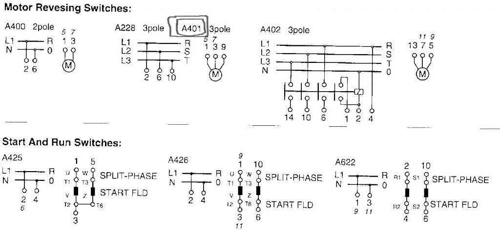 Thank you again, gentlemen- particularly for your patience. I have scanned the diagram sheet (hopefully, the relevant bit) and will attempt to attach it. I have tried to highlight the specific model area with a (badly drawn) box. If you feel that you can translate it into terms suitable for my limited expertise, I would be very grateful Bill |
| Les Jones 1 | 16/12/2009 11:01:32 |
| 2292 forum posts 159 photos | Bill I can see why you find the diagram confusing as the switch in the diagram has its connections numbered 1,2,3,5,6,7,9,10 and the switch you have is numbered L1,L2,L3, N (Plus I think there must be more than those four connections.) I have had a look at Kraaus & Naimers website and there diagrams show their switches with just numbers for the connections. Here is a picture of one of their three position switches showing the connections for both a single phase and a three phase motor.  Are you sure the switch is made by Kraaus & Naimer ? I am not sure if the links between contacts that do not have connection numbers are accessible or are internal links. Are there any part numbers on your switch ? If there are we may be able to get more information. One other possibility is if you bought the switch from RS or Farnell etc then their stock code would help with finding information. By the way bill you did well attaching the image. I did not realise it was so messy to do on this website. I thought I could just copy and past the image to the reply. (Or click an attach button.) It took me some time before I realised the image had to be uploaded to the website first. Les. |
| Ian S C | 16/12/2009 11:36:54 |
 7468 forum posts 230 photos | Les,the switch was bought in 1995 so the in fo might not be on the web,I'v been looking for info on a Horstmann auto time control switch,no luck yet though its proberbly 50 yrs old at least.They proberbly only put up current stuff.Ian.S C |
| Cornish Jack | 16/12/2009 14:31:01 |
| 1228 forum posts 172 photos | Les, thank you again for your exceptional inputs. You're right about the confusion re. numbers and L1. L2etc. I'll have a closer look at those diagrams you posted and see if they make more sense. Switch was bought from a local retailer who had to do a real rummage search to find it!! It is labelled Kraus and Naimer, model number A401/GBA001. There are 10 connections, 1/2, 5/6 and 9/10 on one side of the barrel and 3/4 and 7/8 on the other side. These connections are separated i.e. 3 and 4 etc. are separated by the central 'spine' of that side of the barrel - similar for the rest. Nothing that I can see which would indicate internal shorts being present. Probably the best bet would be to get the AVO out and note the continuities for all selections - thay should keep me out of mischief for a while. Re. attaching the image - yes, it IS different, not helped by the scanner/copier going 'on the blink' and having to be replaced (at 1A.M.!! ) Ian S C - thank you for the suggestion but the switch was a RECENT purchase, having lost the original which came with the kit in '95. If I was much. much tidier and didn't move locations so much, I might have managed to retain the original |
| Les Jones 1 | 16/12/2009 21:16:08 |
| 2292 forum posts 159 photos | Hi Bill, Things are now becoming clear. The 10 connections suggests that this switch has 5 sets of contacts. This is enough to reverse a three phase motor with the windings fully isolated in the off position. I am pretty certain this switch would work in your application but with only 5 sets of contacts neutral would be still connected to the run winding in the off position. This is not good practice from the safety point of view so I would not recommend it. If you do decide to use it I will try to describe the tests to make with your AVO to identify which pairs of connections have the reversing function. One input will go to the same output in forward and reverse positions. Les. |
| Cornish Jack | 16/12/2009 22:37:15 |
| 1228 forum posts 172 photos | Thank you Les. I'm afraid that examining the 3 phase switch diagram made my brain hurt!! It makes it seem that the contacts are only capable of being 'made' or 'unmade' which doesn't gel with my image of a 3 way switch (Off, Forward and Reverse.) I have, no doubt, got it completely wrong. However, if you could point me towards appropriate AVO checks, I might be able to see a tree or two in the impenetrable forest  Bill |
| mgj | 16/12/2009 23:05:53 |
| 1017 forum posts 14 photos | The other option is to use a double pole NVR switch for on off. ie the rotary switch is used solely for reversing and lives permanently on at forwards, and the on off bit is done by a proper NVR switch. That's the safest solution, NVR switches being "good things". I didn't realise that this thing had no NVR facility, and one really ought to have one of those in the line. Then it wouldn't matter if neutral remained hooked up to the far end of the run windings. That's how I set up the Myford while I bothered to have a reversing switch. The other point is - do you really need to reverse this thing? I have a Quorn for tool and cutter grinding. I never bother to reverse it because in "normal mode" the sparks all go down away from ones face. With fine stones it doesn't seem to matter to the tool if you grind with or against hte edge. In any case you can set a tool up to grind in either direction. (either side of the stone) if you want to. Edited By meyrick griffith-jones on 16/12/2009 23:11:59 |
| Les Jones 1 | 17/12/2009 11:03:47 |
| 2292 forum posts 159 photos | Hi Bill, In these switches all 5 contacts are just on or off. They are operated by cams. In the stop position the cam does not close any contacts. One of the 5 contacts will be closed by a cam in both the forward and reverse positions. Of the four other contacts two will be closed in the forward position (Open in reverse) The other two will be closed in the reverse position (Open in forward.) The switch probably has some of the connections to the contacts linked internally. Meyrick's idea to use an NVR switch is a good one if you have space in the control box. (Remember I have not seen any pictures of your grinder.) By the way an NVR switch switches off if the power is removed so that the machine never starts by itself when it is plugged in. Another possibility would be to break the neutral to the run winding with a single pole relay (Of suitable rating.) The coil would be connected in parallel with the start winding. (On the side of the start capacitor connected to the switch.) It may be easier to talk you through metering the switch on the phone. I will give you an email address that I use for situations like this. (Where it open to be read by anyone.) les_jones at talk21.com (Do not type at, use the @ symbol. This is to stop it being recognised automatically as an email address.) You can then send me your email adress or phone number and suggest times when you would want me to phone you. My phone package gives free calls for the first hour to normal numbers. Les. |
Please login to post a reply.
Magazine Locator
Want the latest issue of Model Engineer or Model Engineers' Workshop? Use our magazine locator links to find your nearest stockist!
Sign up to our Newsletter
Sign up to our newsletter and get a free digital issue.
You can unsubscribe at anytime. View our privacy policy at www.mortons.co.uk/privacy
Latest Forum Posts
- *Oct 2023: FORUM MIGRATION TIMELINE*
05/10/2023 07:57:11 - Making ER11 collet chuck
05/10/2023 07:56:24 - What did you do today? 2023
05/10/2023 07:25:01 - Orrery
05/10/2023 06:00:41 - Wera hand-tools
05/10/2023 05:47:07 - New member
05/10/2023 04:40:11 - Problems with external pot on at1 vfd
05/10/2023 00:06:32 - Drain plug
04/10/2023 23:36:17 - digi phase converter for 10 machines.....
04/10/2023 23:13:48 - Winter Storage Of Locomotives
04/10/2023 21:02:11 - More Latest Posts...
- View All Topics
Support Our Partners


Shopping Partners
Subscription Offer

Latest "For Sale" Ads
- Reeves** - Rebuilt Royal Scot by Martin Evans
by John Broughton
£300.00 - BRITANNIA 5" GAUGE James Perrier
by Jon Seabright 1
£2,500.00 - Drill Grinder - for restoration
by Nigel Graham 2
£0.00 - WARCO WM18 MILLING MACHINE
by Alex Chudley
£1,200.00 - MYFORD SUPER 7 LATHE
by Alex Chudley
£2,000.00 - More "For Sale" Ads...
Latest "Wanted" Ads
- D1-3 backplate
by Michael Horley
Price Not Specified - fixed steady for a Colchester bantam mark1 800
by George Jervis
Price Not Specified - lbsc pansy
by JACK SIDEBOTHAM
Price Not Specified - Pratt Burnerd multifit chuck key.
by Tim Riome
Price Not Specified - BANDSAW BLADE WELDER
by HUGH
Price Not Specified - More "Wanted" Ads...
Get In Touch!
Do you want to contact the Model Engineer and Model Engineers' Workshop team?
You can contact us by phone, mail or email about the magazines including becoming a contributor, submitting reader's letters or making queries about articles. You can also get in touch about this website, advertising or other general issues.
Click THIS LINK for full contact details.
For subscription issues please see THIS LINK.
Digital Back Issues


Donate

 Register
 Log-in
Model Engineer Magazine
- Percival Marshall
- M.E. History
- LittleLEC
- M.E. Clock

ME Workshop
- An Adcock
- & Shipley
- Horizontal
- Mill

Subscribe Now
- Great savings
- Delivered to your door

Pre-order your copy!
- Delivered to your doorstep!
- Free UK delivery!
All Forum Topics > Workshop Tools and Tooling > Perfecto shaper