Forum sponsored by:

Opus Proximum
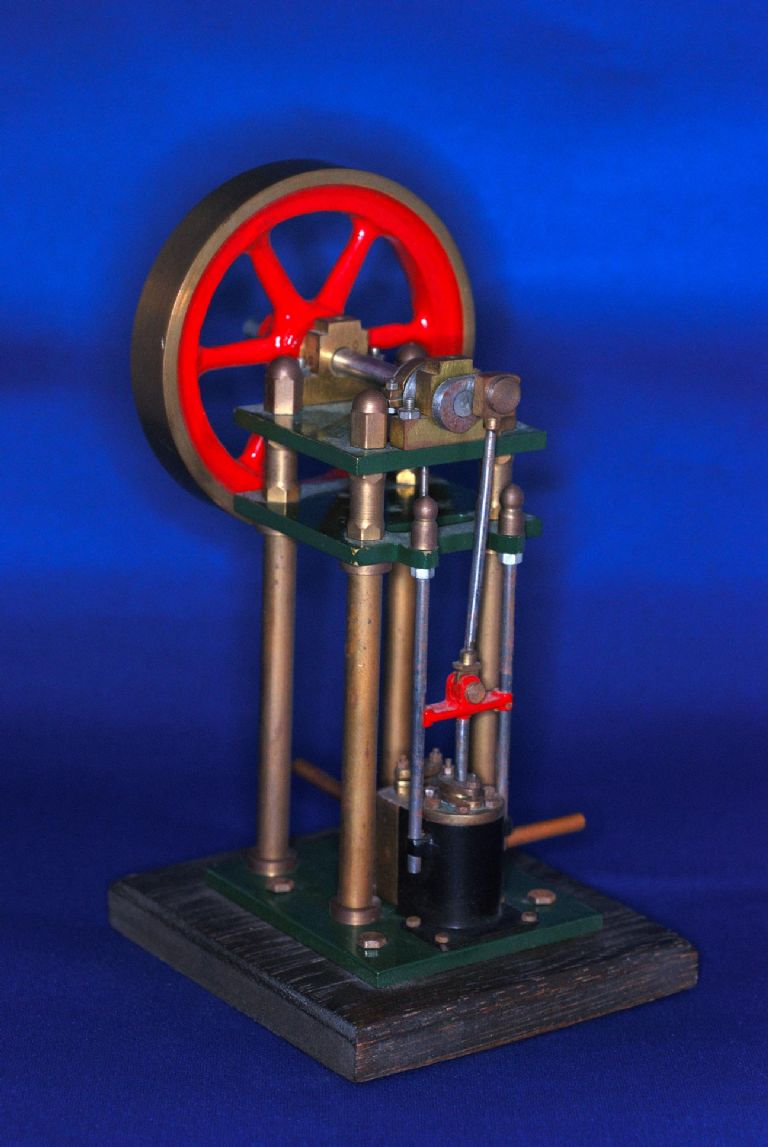
Anomalies in plans
| John Somers 1 | 31/10/2009 11:59:15 |
 36 forum posts | I am curious to know if anyone else has run into what appear to be errors in the plans and build notes for Stan Bray's Opus Proximum, a verticle engine featured in The Best of Model Engineer, Volume 1, currently on sale at WH Smith. Initial study of the article raises a query on the photo of the main bearings and crankshaft on page 29. This bears no relationship to the arrangement shown in the plans. Having decided to build this engine 50% larger than the plans and to the metric version I next discovered the valve chest cover is shown as 15mm wide whilst the chest is 16mm wide. Surely they should be to the same width ? Following the machining of the cylinder I then machined up the Valve Chest and clearly the depth of the chest is out of proportion and should be reduced from the stated 12mm to something like 8mm which would provide adequate clearance for the sliding valve. I would be interested to hear from anyone else who may be encountering difficulties. JohnS |
| David Clark 1 | 31/10/2009 12:45:21 |
 3357 forum posts 112 photos 10 articles | Hi There
The photo is incorrect.
Change any dimensions to suit your needs.
The drawings are Stan's originals from the magazienand were only tidied up, not altered.
Send me a photo when finished for Model Engineer.
regards David
|
| JasonB | 01/11/2009 20:35:32 |
 25215 forum posts 3105 photos 1 articles | There is one being built here you may want to ask about any drawing errors
Or is that you???
Jason Edited By JasonB on 01/11/2009 20:38:47 |
| John Somers 1 | 02/11/2009 09:53:26 |
36 forum posts | Hi Jason Yes it is ! Sorry if I caused any confusion. JohnS |
| James Veitch | 04/11/2009 02:31:41 |
| 16 forum posts | Greetings,
I'm thinking of building the Opus Proximum engine. I'm a novice so excuse any of the following that's off base.
As a first step I'm modeling the Opus P. with a 3-D modeling program. This
is proving to be a good exercise. First it makes me read the
instructions carefully. Secondly it makes me look at the drawings
carefully. Thirdly it makes me think about how I will actually go about making the real item. I've already found several minor points of confusion or
perhaps errors in the material as presented. That's all fair enough
and not a big problem. The act of modeling on the computer has helped
catch some of these. I'm not finished modeling yet but here is what I've found so far: 1. The diagram titled: BASE PLATE, p. 23. a.
There are 4 holes shown to the right side of the plate. They are
arranged in a rectangle of 5 mm by 22 mm. PHOTO 1 and the photo above
PHOTO 1 show the holes are not in a rectangle. The diagram CYLINDER
BASE (p.24) shows the 4 holes in a rectangle of 12 by 19 mm. The
stated hole sizes also disagree, i.e.: 12BA to 10BA. b. The photo of the finished item on p. 22 shows 4 additional hole are needed to mount the BASE PLATE to a wooden platform. 2. The diagram titled: MOTION PLATE, p.23. a.
The size and position of the rectangular hole are not specified. Is
the size of 4 X 19 mm correct? Is the position from the top right
corner as 11 mm down and 4 mm in, correct? b. The
distance between the holes in the two tabs on the right edge of the
plate are not specified. Looking at the diagram CYLINDER p. 24 I
believe the holes should be 19 mm apart. Is that correct? |
| John Somers 1 | 04/11/2009 06:40:32 |
36 forum posts | Hello James As you are discovering there are a number of anomalies with the plans for Opus Proximus which gives rise to the question of whether it's a suitable project for anyone starting out in model engineering. However your interest in computer modelling could make this something of a challenge and will enable you to consider correcting some of the discrepancies. I am assuming that you are planning to build in metric dimensions and I would suggest that you follow suit with your fasteners. Clearly there are some dimensions that are critical but the position of mounting holes can be altered provided it does not alter the position of the component or its relationship to other parts. Your 3D modeling approach will at least provide you with the opportunity of deciding on the final position of mounting holes from both practical and aesthetic points of view. Like you I also deduced that the holes in the two tabs are 19mm apart and should match the two holes on the lugs of the motion plate and of course the cross head shown on page 28. Clearly the aim is for the cross head to slide smoothly on the two slide bars. I have made a start on the construction of Opus P and opted for increasing the size by 50%. This will provide a more substantial model and certain parts will be easier to produce. The increased cost of materials is minimal. I am covering the build of Opus P on my website/blogStart Model Engineering and you may find this of interest. JohnS |
| Circlip | 04/11/2009 10:18:25 |
| 1723 forum posts | IIRC Op. Prox. was one of a series of engines that had dual dimensions to appease the growing grumbles from the ranks of the "Why no metric designs"???
Sadly, unless the design gives the EXACT numerical equivalent from WHICHEVER system is used, approximations introduce errors rapidly. 25mm is NOT 1" and neither is 1/2" 12 or 13mm.
I wouldn't be surprised that if you worked the parts in imperial it fits and works??
Years ago, the D/O I worked in used to have to go into the works to "Sort out" percieved Drawing errors. When you have to start at one end of a machine and check out why a bracket on an assembly 30Ft away doesn't line up, it doesn't take many "proud sixteenths" or "Shy eighths" to loose OR gain inches at the other end.
When the workings of a mechanism are UNDERSTOOD it doesn't matter which system is used providing you design the bits using the appropriate sized materials FOR THAT SYSTEM. Sadly, cos some of the CAD programmes mean that most can now draw straight lines and lines that intersect at right or whatever angle can be specified, it DOESN'T mean that they are DESIGNERS.
To Illustrate, 1" - 1/8" twice = 3/4" OR 25.4 minus 3.2 Twice = 19, BUT 3/4" = 19.08. In the case of using 25mm wide material, a subtraction of 3mm per side for something like column centres matters not a s*d, but 25.4 minus 3 twice, although in the example given doesn't matter for column centres but can be disaster for valve or pitch settings.
Unfortunately quite a few of Stans designs have been critisized by whingers (Present company excepted) and copyers who try to change things without understanding the implications.
A colleague is at presant making an engine originally designed in imperial. Luckyly he has someone to help with the IMPORTANT sizes to maintain and the "Floaters", providing a few down the line are taken into account, CAN be solid Metric.
Regards Ian. |
| John Somers 1 | 05/11/2009 16:18:33 |
36 forum posts | And there was me thinking that if I came across a set of plans for a model engine that had been converted into metric I could actually build it and it would run. Ah well, you learn something new every day. I think I will stick with my Elmer Verburg's plans and my handy imperial to metric conversion chart. John S |
| John Somers 1 | 18/11/2009 07:34:12 |
36 forum posts | I would be interested to hear from anyone building Stan Bray's Opus Proximum. I reckon I am now about two thirds through the build and having sorted out some early problems the project is coming together nicely. You can view my progress here. I have had a few problems along the way and my blog may provide fellow builders with some food for thought. I am building my Opus Proximum 50% up in size and several times I have felt sympathy for anyone building to the plan size. Making parts like the eccentric strap and the steam valve must call for a very steady hand and sharp vision. My thoughts are now turning to the finish. Personally I am not too keen on the red and green engine finishes on this size of engine so I may leave mine in polished aluminium, stainless steel and brass though I might consider painting the three main horizontal plates in satin black. As these are aluminium an initial coat of etching primer is pretty much essential. Today I shall be tackling the cross head but I am planning to machine this out of brass bar rather than silver solder three or four components together. I reckon this will give me better control of the critical final dimensions. John S |
| Circlip | 18/11/2009 11:30:35 |
| 1723 forum posts | As an alternative to the "Normal" paint finishes John, cos you're using materials capable of showing it off to advantage, have you thought about Chemical finishes??
Regards Ian. |
| John Somers 1 | 18/11/2009 16:14:27 |
36 forum posts | Now there's a thought Ian. I have some blackening and antiquing chemicals bought when I had grand idea on styling a pushrod type engine on an old Rudge motorcycle engine - but that's another story ! Anyway you have given me something to think about - thanks. John S |
| JasonB | 18/11/2009 16:49:18 |
25215 forum posts 3105 photos 1 articles | I like the black finish, with just a few parts left in bare steel & brass. Was looking at this guys site the other day and he uses a black etching process that seems to work on alloy & brass, its the "Seamann Atztechnik link, best if you put the page url into a translator like babblefish.
Jason |
| John Somers 1 | 18/11/2009 19:35:49 |
36 forum posts | Inspirational work Jason. Seems like some further research might be worthwhile. John S |
| JasonB | 18/11/2009 19:53:26 |
25215 forum posts 3105 photos 1 articles | The black sems a very dense coating, hard to tell its not painted, but seems to have the advantage of a very thin layer( or disadvantage if you want to hine tool marks)
Don't know if you found your way to the rest of his models but this should take you there
Jason |
| John Somers 1 | 14/09/2010 16:22:12 |
36 forum posts | It is getting on for ten months (doesn't time fly !) since I started building Stan Brays Opus Proximum and whilst it has been a struggle I am now pleased to report that at last it is up and running. Those interested can see the step by step build log and the final outcome at http://start-model-engineering.co.uk/2010/09/14/opus-proximum/opus-p-now-running/ John S |
| John Shepherd | 14/09/2010 18:21:26 |
| 222 forum posts 7 photos | I built the Opus when it first (I think) appeared and found several errors and wrote to the then editor of ME stating what I found hoping that it would help others.
My letter was not published but to my surprise I received a letter from Stan Bray along the lines of' who was I to question his drawings'!
Furthermore it would appear that the mistakes have not been corrected in reprints although I did not keep a record of what I found so I could not say if the errors are original or if others have crept in.
John Shepherd
|
| John Somers 1 | 14/09/2010 19:49:27 |
36 forum posts | You are not the first to get your knuckles wrapped upon querying anomalies In Mr Brays drawings. I am curious to know if despite this your endeavours were successful and you finished up with a runner - anyt chance of any pics ? John-Som |
| David Clark 1 | 14/09/2010 20:11:40 |
3357 forum posts 112 photos 10 articles | Hi There
Because the drawings and articles were done by a previous editor, they were republished without corrections.
Had I know how bad they were, I would not have used them.
regards david
|
| John Shepherd | 15/09/2010 18:57:33 |
| 222 forum posts 7 photos | I am afraid to say my Opus is not a runner. I had a lot of trouble with the valve gear and I gave up as I became convinced it was not going to run well anyway.
Photo as requested - it is a bit dirty and tarnished as I have just got it down from the loft.
Perhaps now it is down I might have another go
 at it and tidy it up. Regards
|
| Rick Hann | 04/07/2020 23:38:12 |
| 21 forum posts | Hi, I realize this an old thread, but I ran across it when looking for information on this engine. I started this little engine more than 20 years ago when I lived in Germany. I made quite a few of the parts and they languished in my unfinished projects box until the Corona Virus hit and I decided to try and complete it. Has anyone actually finished this little engine? When I got down to actually putting pieces together, I soon found out the their were several dimensional errors that required binning several parts. Not wanting to be accused of being a whinger, I would like to hear from anyone who has built this engine and could give me a heads up on problems they may have encountered. Thanks. Rick Hann |
Please login to post a reply.
Magazine Locator
Want the latest issue of Model Engineer or Model Engineers' Workshop? Use our magazine locator links to find your nearest stockist!
Sign up to our Newsletter
Sign up to our newsletter and get a free digital issue.
You can unsubscribe at anytime. View our privacy policy at www.mortons.co.uk/privacy
Latest Forum Posts
- hemingway ball turner
04/07/2025 14:40:26 - *Oct 2023: FORUM MIGRATION TIMELINE*
05/10/2023 07:57:11 - Making ER11 collet chuck
05/10/2023 07:56:24 - What did you do today? 2023
05/10/2023 07:25:01 - Orrery
05/10/2023 06:00:41 - Wera hand-tools
05/10/2023 05:47:07 - New member
05/10/2023 04:40:11 - Problems with external pot on at1 vfd
05/10/2023 00:06:32 - Drain plug
04/10/2023 23:36:17 - digi phase converter for 10 machines.....
04/10/2023 23:13:48 - More Latest Posts...
- View All Topics
Support Our Partners


Shopping Partners
Subscription Offer

Latest "For Sale" Ads
- Reeves** - Rebuilt Royal Scot by Martin Evans
by John Broughton
£300.00 - BRITANNIA 5" GAUGE James Perrier
by Jon Seabright 1
£2,500.00 - Drill Grinder - for restoration
by Nigel Graham 2
£0.00 - WARCO WM18 MILLING MACHINE
by Alex Chudley
£1,200.00 - MYFORD SUPER 7 LATHE
by Alex Chudley
£2,000.00 - More "For Sale" Ads...
Latest "Wanted" Ads
- D1-3 backplate
by Michael Horley
Price Not Specified - fixed steady for a Colchester bantam mark1 800
by George Jervis
Price Not Specified - lbsc pansy
by JACK SIDEBOTHAM
Price Not Specified - Pratt Burnerd multifit chuck key.
by Tim Riome
Price Not Specified - BANDSAW BLADE WELDER
by HUGH
Price Not Specified - More "Wanted" Ads...
Get In Touch!
Do you want to contact the Model Engineer and Model Engineers' Workshop team?
You can contact us by phone, mail or email about the magazines including becoming a contributor, submitting reader's letters or making queries about articles. You can also get in touch about this website, advertising or other general issues.
Click THIS LINK for full contact details.
For subscription issues please see THIS LINK.
Digital Back Issues


Donate

 Register
 Log-in
Model Engineer Magazine
- Percival Marshall
- M.E. History
- LittleLEC
- M.E. Clock

ME Workshop
- An Adcock
- & Shipley
- Horizontal
- Mill

Subscribe Now
- Great savings
- Delivered to your door

Pre-order your copy!
- Delivered to your doorstep!
- Free UK delivery!
All Forum Topics > General Questions > Opus Proximum