Forum sponsored by:

Boxhill by Martin Evans
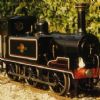
Driving Wheels
| TED ROGANS | 23/09/2009 13:49:34 |
| 2 forum posts | The drawings for Boxhill in "The Best of Model Engineer" are a copy of the original drawings published in the Model Engineer. Martin Evans made a correction in a later article on the construction. This was that the balance weights should be finished flush with the tyres. Apart from being true to the prototype this simplifies the turning of the wheels.
Unfortunately the drawings were never been corrected. |
| David Clark 1 | 23/09/2009 14:25:12 |
 3357 forum posts 112 photos 10 articles | Hi There
Do you know which issue the correction was in?
regards David
|
| TED ROGANS | 20/10/2009 10:49:54 |
| 2 forum posts | Yes, the correction occurred in the very first paragraph of the next issue after instructions for machining the wheels, October 1st 1963. This must have been very frustrating for anyone who had already finished the wheels, after setting up on a face plate or in a chuck with the chunky balance weight of the Reeves castings sticking out. I did tell Reeves about this many years ago but no action was taken. I suppose the plans would have to be updated before they could change their patterns.
|
| Peter D Hingley 1 | 05/11/2009 14:47:35 |
| 3 forum posts | I am sorry to say that, in general, the quality and accuracy of drawings sold for model engineers is pretty abysmal. One chap I know, a highly experienced model engineer, was busy building a 5 inch 'Duchess' complete with all 4 cylinders, carefully made and stored away the very complex crank axle and the coupled ones , then turned all the coupled wheels exactly to drawing, then discovered that the holes in the wheels were bigger than the wheel seats !! He wrote to complain to the publishers of the drawings who just said oh well, you are an engineer, you should have checked ! But surely if one has paid a sizeable chunk of money ( and a full set of drawings for a large and complex loco costs a very tidy sum) one has a right to expect that they will be accurate and that any errors have been corrected. A draughtsman who made that sort of error in industry would be sacked and quite rightly too.
But I am afraid this is a very similar situation to kits made for smaller scale modelling such as 0 gauge. These vary from absolutely wonderful (such as Martin Finney and David Andrews) to the abysmal and virtually unbuildable. Consumer legisation offers little realistic redress and one's only recourse is to rely on reviews and other peoples' knowledge and experience, and for that this kind of forum is invaluable !
Peter D Hingley |
| Andrew Loubser | 23/04/2011 10:28:17 |
| 2 forum posts | I am currently constructing Boxhill as per the plans provided but to 71/4 inch gauge. The placement of the two oval openings in the frames in relation to the wheels is not evident e.g. no measurements to indicate how far from the front or rear wheel centreline it is.
I am pleased with this model chosen by Model Engineer to provide the plans for as in our club we have open days steaming and take passengers for rides. This model shows every promise to pull exceedingly well.
Edited By Andrew Loubser on 23/04/2011 10:29:07 |
| Weary | 23/04/2011 11:35:55 |
| 421 forum posts 1 photos | I guess that you know that Don Young designed and described a 7.25" gauge IOW Terrier 'Newport'. I assume that the cut-outs are standard amongst the class.
I have checked the Don Young drawings (sheet 3, illustrated Locomotives Large and Small No.52, August 1992) and these seem to be the relevant details as drawn by Don.....
Both the cut-outs shown as 1 7/16" (one and seven sixteenths) high, and rounded to that diameter at each end. The radius centre to radius center of the end radii of the front -cut-out is 2 3/8" (two and three eighths), that of the rear cut-out is 3 5/8" (three and five eighths).
The bottom edge of both cut-outs is 5/8" (five eighths) above the frame edge immediately below the cut-outs.
The center of the radii nearest the center wheels of the two cut-outs are 2 13/16" (two and thirteen sixteenths) from the centre-line of the middle axle.
Hopefully some of that fits with the 'Evans' drawings.
There also seems to be a round openings to the rear of the rear axle, but I guess Mr Evans has specified that position. Don makes that 1 7/16" (one and seven sixteenths) diameter too.
Regards,
Phil Edited By Weary on 23/04/2011 11:41:32 |
| Andrew Loubser | 23/04/2011 21:46:34 |
| 2 forum posts | Phil
Thank you for the prompt reply. The info is spot on. Any information is valuable especially drawings to collate.
My Club is the Western Province Live Steamers in Cape Town South Africa. W've just hosted the National Steam Meet for four days and was it a blast! |
| Weary | 23/04/2011 22:36:25 |
| 421 forum posts 1 photos | Reeves 2000 can supply the drawings and castings for the Don Young 7.25" gauge 'Newport'.
Mr Loubser, please check your messages. Edited By Weary on 23/04/2011 22:44:04 |
| John Olsen | 24/04/2011 05:59:48 |
| 1294 forum posts 108 photos 1 articles | Well, how about a section here for some of the more popular models, where errors and improvements can be described. This does not of course help the guy who does not have Internet access, but it would help with what is otherwise a very difficult problem, which is getting a correction out to all the people who might need it. Even if a correction gets published in the magazine, there is no certainty that the future builder will find it, and with printed set of plans, I suspect once a print run has been done, that will be used until they run out. But if the prospective builder knew that they might find some useful information here, it could save a lot of wasted effort. regards John |
| Colin Jacobs 1 | 29/04/2011 20:01:42 |
| 69 forum posts 2 photos | This could even make a magazine page? |
| John Olsen | 30/04/2011 01:15:45 |
| 1294 forum posts 108 photos 1 articles | The trouble with a magazine page is that you may not have that particular page available a few years later when you buy a set of plans and set out to build a model. Websites can of course disapear too, but useful information seems to have a habit of staying available. regards John |
| Weary | 30/04/2011 09:20:48 |
| 421 forum posts 1 photos | For those unaware of it, this site might be of interest as it lists many errors. |
| Alan Stewart 2 | 01/05/2011 17:58:34 |
| 3 forum posts | The real problem with Boxhill wheel castings is, I think, that the weights are 90° out of place. Cranked wheels for small locos have the counter weights at right angles to the coupling pin. The coupling pins are opposite the nearest crank and the weight is opposite the far crank hence putting the weight at 90° to the coupling pin. Box Hill weights are opposite the coupling pins! I suppose the recommendation to machined the weights flush with the wheels is to reduce the out of balance effect that I think the weights will produce. I have already resolved to leave the weights protruding (as I think they would not look good flush) but to drill a few holes in them and add balance weights |
| Alan Stewart 2 | 04/05/2011 15:57:43 |
| 3 forum posts | |
| Alan Stewart 2 | 04/05/2011 16:03:46 |
| 3 forum posts | Looking at the cranked wheels of GW engine 6412, the balance weights on the cranked wheels are at about 60° rather than 90° to the coupling pin so I now think they are for balancing the eccentrics which are between the cranks. |
| julian atkins | 13/06/2011 09:19:36 |
 1285 forum posts 353 photos | Stroudley had his own pet ideas about balancing cranks, and position of crankpins vis-a vis the crank axle... the balance weights were large and crescent shaped and at 180 degrees to the crank axle webs. the crankpins were in the same position and in line with the crank axle webs/connecting rod pins for each side of the engine. martin evans explains this on p. 360 ME 15th sept 1963, and there is no error in his drawings for the wheels, apart from the fact that to be true to prototype the balance weights are flush with the spokes which as already commented upon he corrected in a later article. it would be quite wrong to follow the 'usual' arrangement of balance weights and their position relative to the crankpins and crank axle on a Stroudley engine! a close examination of photographs of Terriers will confirm this. hope this helps. |
| julian atkins | 13/06/2011 09:50:53 |
1285 forum posts 353 photos | by the way, martin evans did take liberties with the buffer beam and running board width to accomodate wider side tanks than prototype, and of course the tanks never protruded into the cab as per one side of BOXHILL. anyone building a model of engines post 1905 needs to check if it was one of the locos fitted for motor train working because these had their buffers raised (see pics of Stepney etc..). A class Terriers should not have a round smokebox as described by martin evans, and the boilers of the prototypes were quite different with the rear of the boiler being shorter and not sitting above the rear axle, and with a large radius to the backhead flange and a completely different arrangement of controls and firehole ring and door 9what an awful backhead he designed when compared to Stroudley's artistic design!). the smokebox diameter and smokebox door diameter should also be larger by 1/4". there are other detail differences between martin evan's drawings and the fullsize locos...the rear drawbar should extend forward as far as the rear axlebox, and martin evans did comment on the use of 'channel' shaped slidebars in his description. the axleboxes had a high lip on their outside face to prevent grit and dirt getting into the axleboxes from the wheels, and of course the prototype engines all had underhung leaf springs which isnt difficult to do in miniature. you will gather from the above that martin evan's side elevation is very accurate to prototype at 1 1/16" scale, but the end elevations are not! i have a copy of the original Stroudley general arrangement drawing from Engineer magazine in 1873. don young's 7 1/4" gauge design NEWPORT is far more accurate to prototype. |
| Dennis Rayner | 13/06/2011 13:23:51 |
 137 forum posts 9 photos | "martin evan's side elevation is very accurate to prototype at 1 1/16" scale, but the end elevations are not!" Nowhere more so than the cab roof which is totally wrong. From the end elevation the cab roof should follow a continuous arc but the Martin Evans drawing shows it as being flat.
So many wonderfully lined out models are spoilt by this massive error. |
| julian atkins | 24/06/2011 13:20:41 |
1285 forum posts 353 photos | Dennis is quite correct about the cab roof... sheet 8 of the drawings shows the shape of the cab for the side elevation as the front elevation! a typical martin evan's error, though to be fair to him the general arrangement drawing on sheet 1 does show the correct front elevation curve to the very distinctive Stroudley cab roof. i would be very interested if anyone has the details of a Gordon Smith type safety valve suitable for Boxhill please? |
Please login to post a reply.
Magazine Locator
Want the latest issue of Model Engineer or Model Engineers' Workshop? Use our magazine locator links to find your nearest stockist!
Sign up to our Newsletter
Sign up to our newsletter and get a free digital issue.
You can unsubscribe at anytime. View our privacy policy at www.mortons.co.uk/privacy
Latest Forum Posts
- hemingway ball turner
04/07/2025 14:40:26 - *Oct 2023: FORUM MIGRATION TIMELINE*
05/10/2023 07:57:11 - Making ER11 collet chuck
05/10/2023 07:56:24 - What did you do today? 2023
05/10/2023 07:25:01 - Orrery
05/10/2023 06:00:41 - Wera hand-tools
05/10/2023 05:47:07 - New member
05/10/2023 04:40:11 - Problems with external pot on at1 vfd
05/10/2023 00:06:32 - Drain plug
04/10/2023 23:36:17 - digi phase converter for 10 machines.....
04/10/2023 23:13:48 - More Latest Posts...
- View All Topics
Support Our Partners


Shopping Partners
Subscription Offer

Latest "For Sale" Ads
- Reeves** - Rebuilt Royal Scot by Martin Evans
by John Broughton
£300.00 - BRITANNIA 5" GAUGE James Perrier
by Jon Seabright 1
£2,500.00 - Drill Grinder - for restoration
by Nigel Graham 2
£0.00 - WARCO WM18 MILLING MACHINE
by Alex Chudley
£1,200.00 - MYFORD SUPER 7 LATHE
by Alex Chudley
£2,000.00 - More "For Sale" Ads...
Latest "Wanted" Ads
- D1-3 backplate
by Michael Horley
Price Not Specified - fixed steady for a Colchester bantam mark1 800
by George Jervis
Price Not Specified - lbsc pansy
by JACK SIDEBOTHAM
Price Not Specified - Pratt Burnerd multifit chuck key.
by Tim Riome
Price Not Specified - BANDSAW BLADE WELDER
by HUGH
Price Not Specified - More "Wanted" Ads...
Get In Touch!
Do you want to contact the Model Engineer and Model Engineers' Workshop team?
You can contact us by phone, mail or email about the magazines including becoming a contributor, submitting reader's letters or making queries about articles. You can also get in touch about this website, advertising or other general issues.
Click THIS LINK for full contact details.
For subscription issues please see THIS LINK.
Digital Back Issues


Donate

 Register
 Log-in
Model Engineer Magazine
- Percival Marshall
- M.E. History
- LittleLEC
- M.E. Clock

ME Workshop
- An Adcock
- & Shipley
- Horizontal
- Mill

Subscribe Now
- Great savings
- Delivered to your door

Pre-order your copy!
- Delivered to your doorstep!
- Free UK delivery!
All Forum Topics > Drawing Errors and Corrections > Boxhill by Martin Evans