Forum sponsored by:

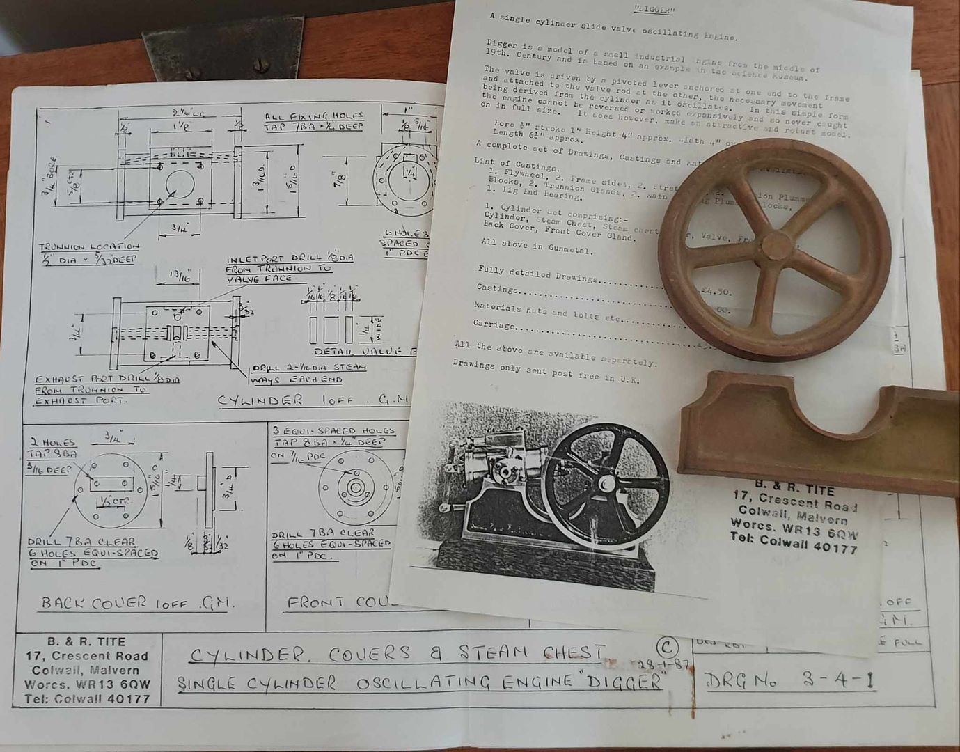
Digger
| JasonB | 26/09/2023 18:29:32 |
 25215 forum posts 3105 photos 1 articles | Firstly I must say sorry to all those who eagarly clicked on the thread title that were looking forward to another off topic gardening thread |
| noel shelley | 26/09/2023 18:39:39 |
| 2308 forum posts 33 photos | An interesting design ! What made it better than a normal slide valve, other than not needing an ecccentric ? Noel. |
| JasonB | 26/09/2023 18:58:58 |
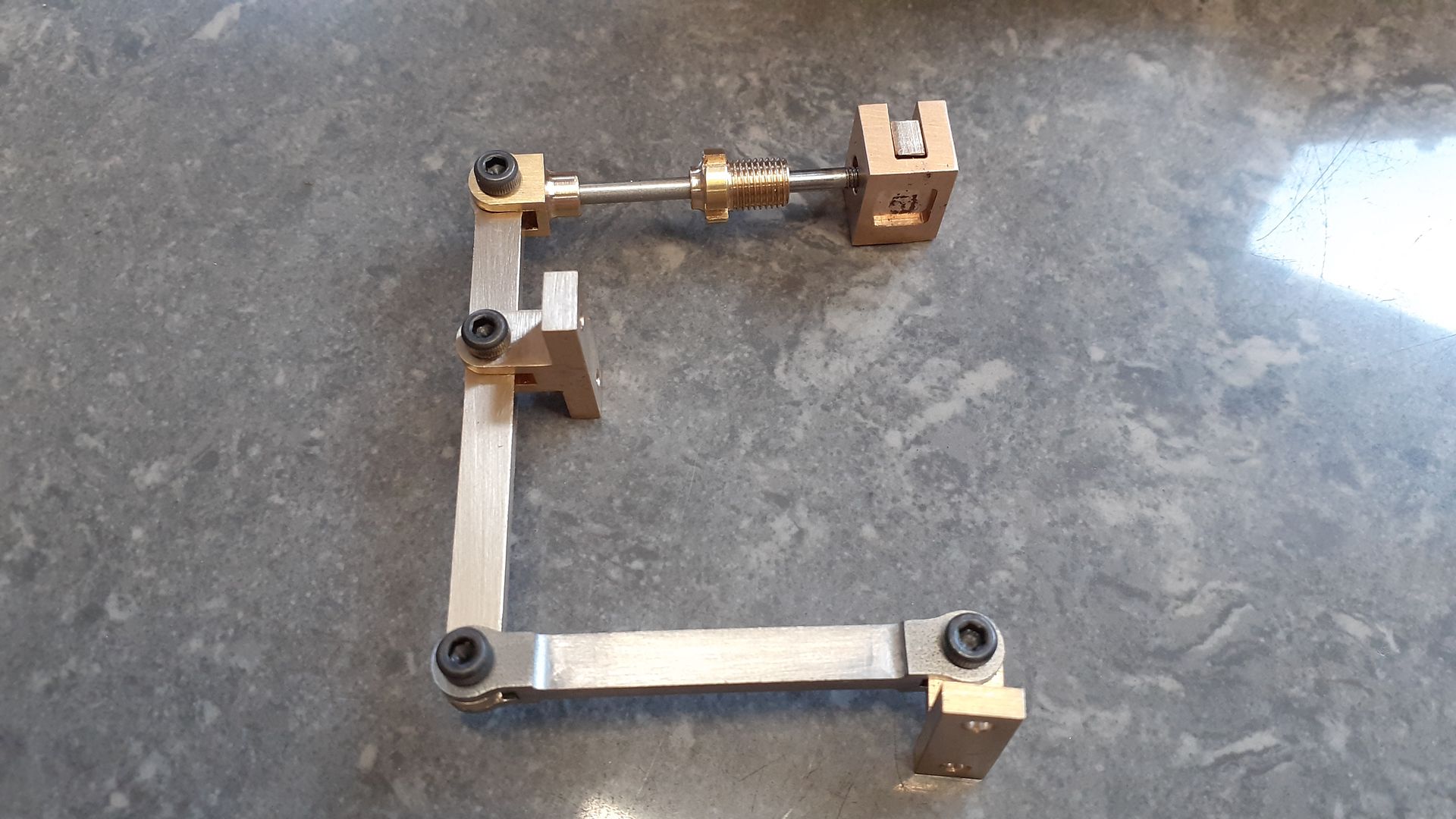
25215 forum posts 3105 photos 1 articles | I'm not sure it is any better than an eccentric driven slide valve, if anything it is a bit more restricting as you can't alter the timing by moving the eccentric on the crankshaft. There are quite a few different arrangements for operating the slide valve with the links in various places relative to the cylinder's point of rotation but I've not seen many with this particular one. I would think it is better than an oscillating engine where the valve arrangement is done by positioning holes in the two faces where cylinder meets trunions as it is easier to seal the shaft of the trunion and not have to worry about the flat faces. As oscillator is also generally a shorter engine than one with trunk or bar guides for the cross head and a separate conrod but a bit harder to construct as the trunions need to be perfectly square to the cylinder/piston rod. Edited By JasonB on 26/09/2023 18:59:59 |
| Ady1 | 26/09/2023 19:56:44 |
 6137 forum posts 893 photos | Had a squirrel and they were still going in May 1993 Same address
Edited By Ady1 on 26/09/2023 20:00:28 |
| JasonB | 27/09/2023 14:51:41 |
25215 forum posts 3105 photos 1 articles | Thanks ADY1 so thats a third engine as I had seen mention of "Hoppy" a hit and miss engine kit they dis that sounds like it may have needed some crankshaft balancing. Though Henry would be the only ready machined of the three. |
| JasonB | 27/09/2023 19:50:36 |
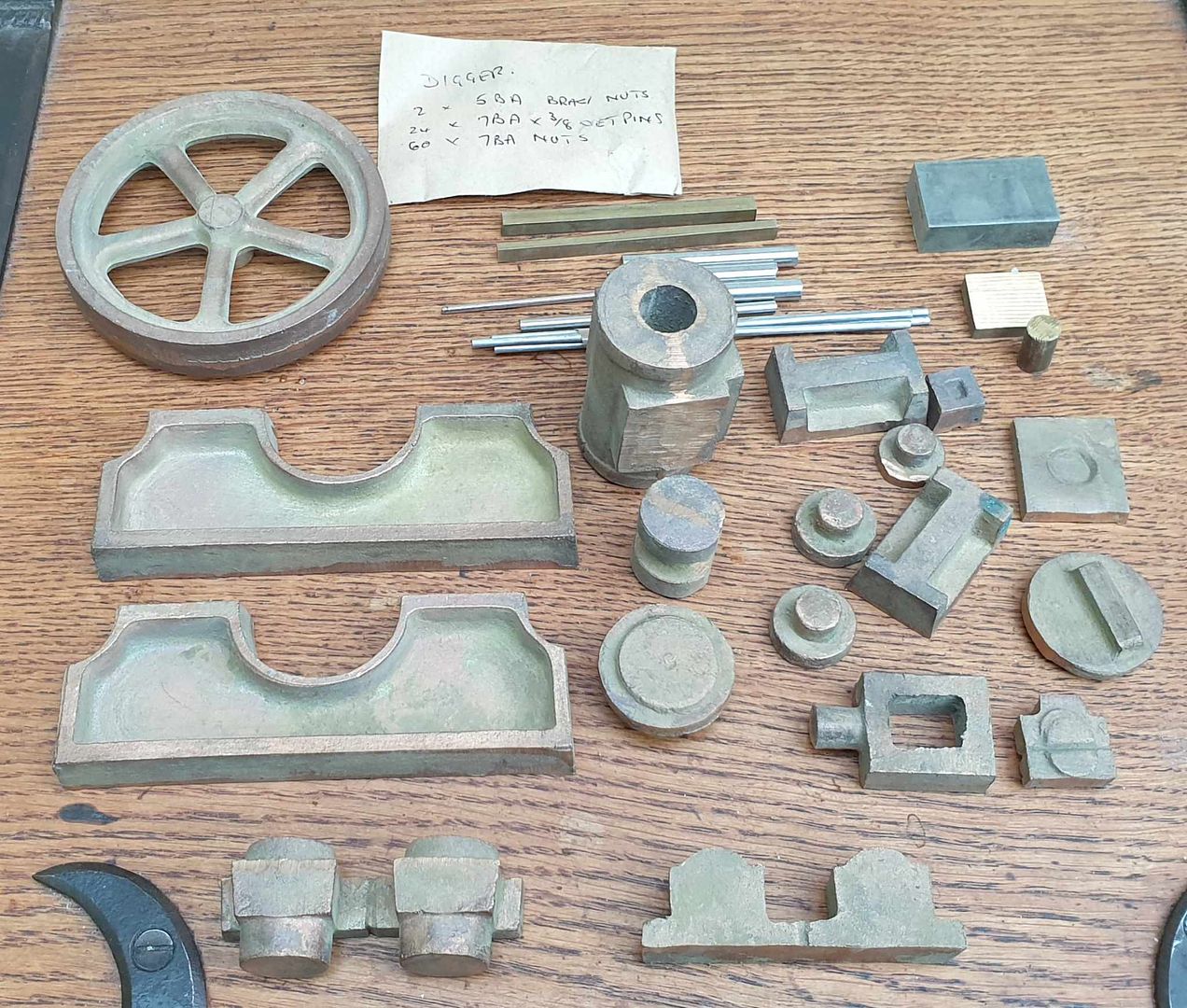
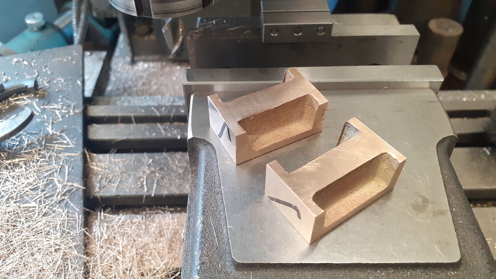
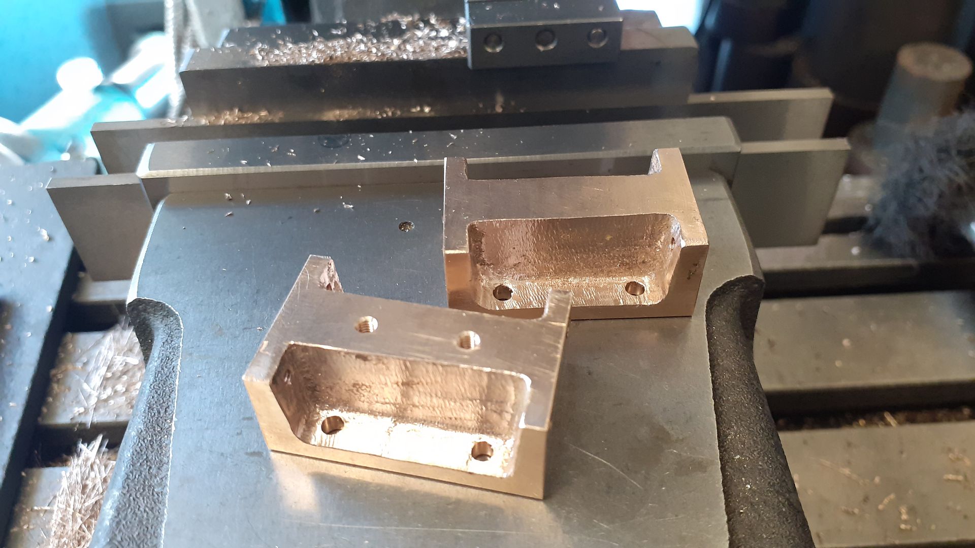
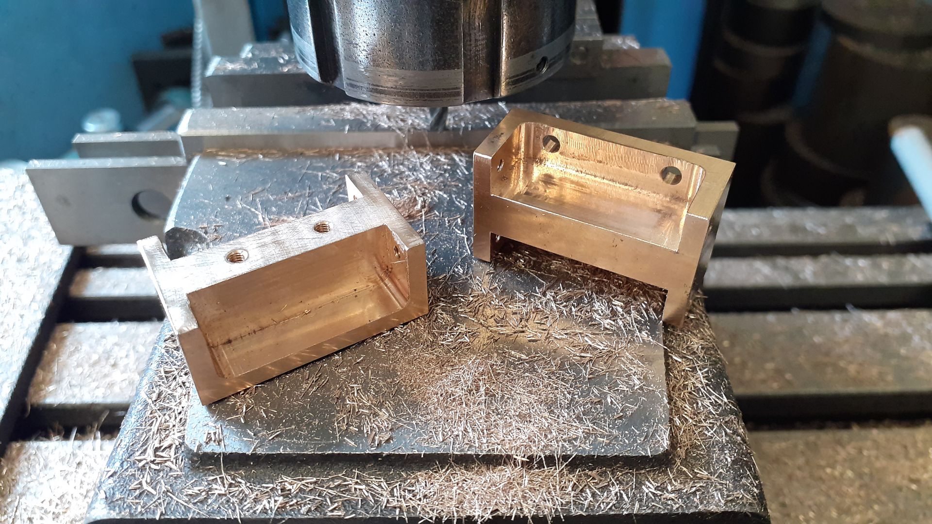
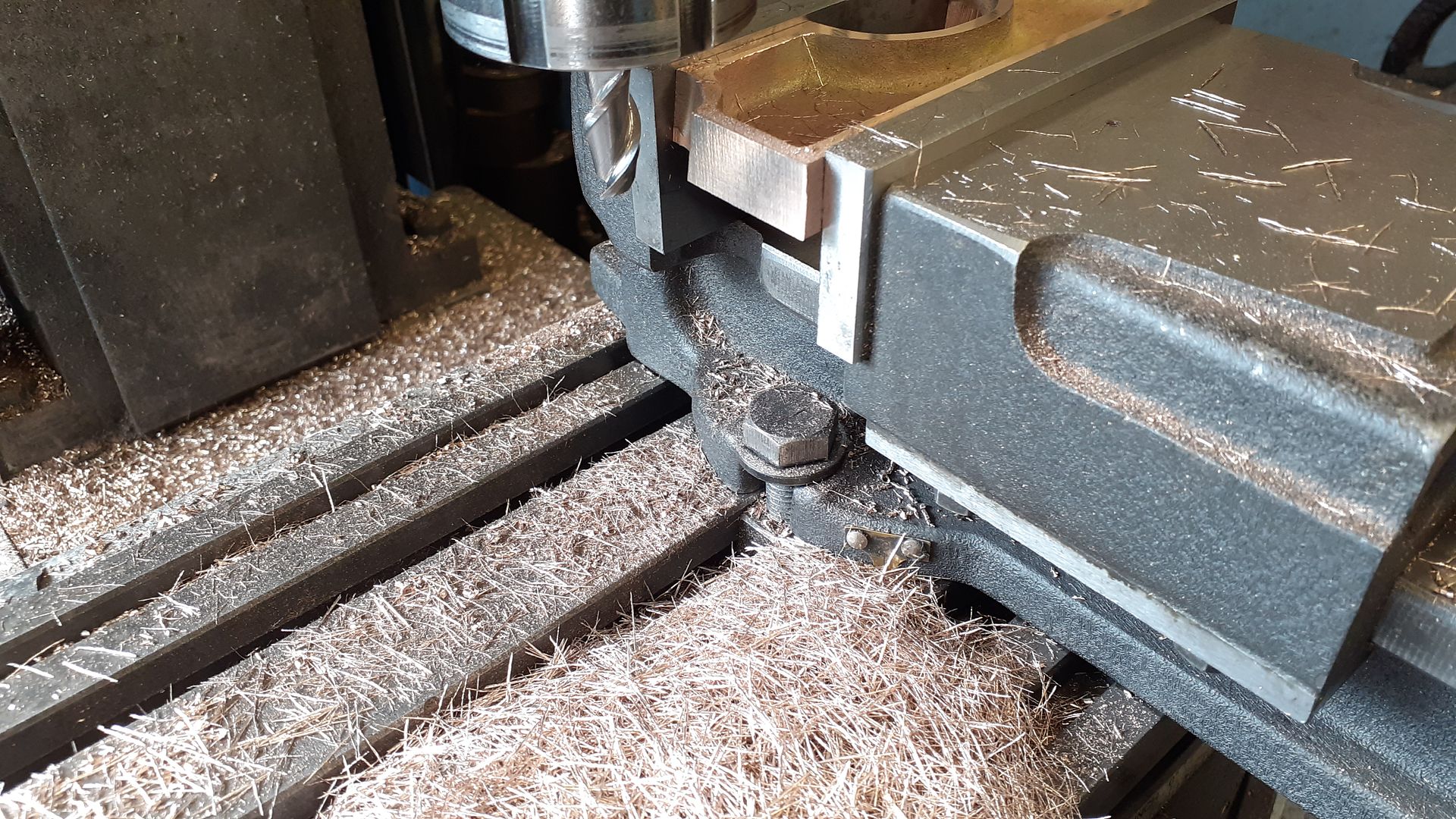
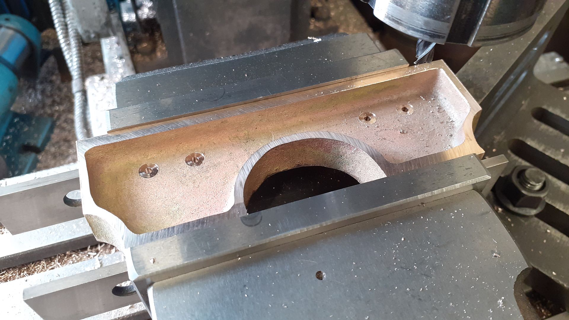
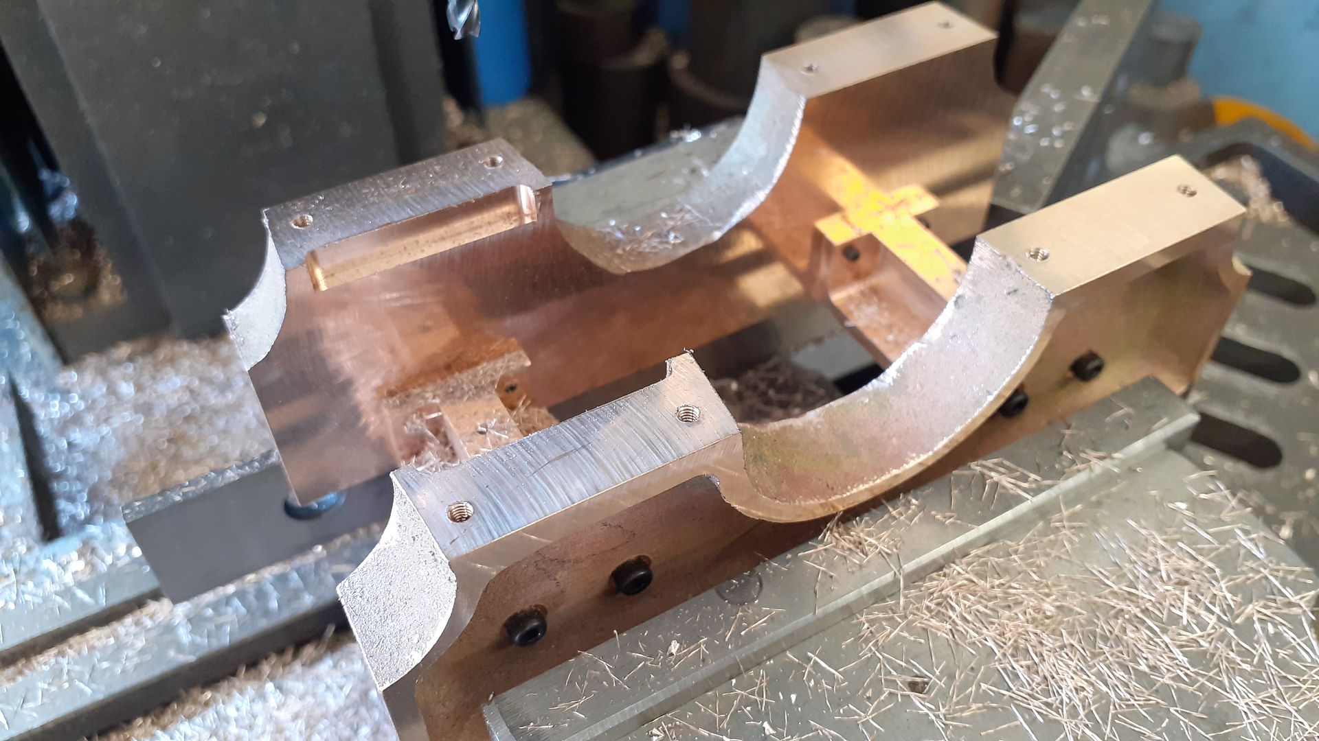
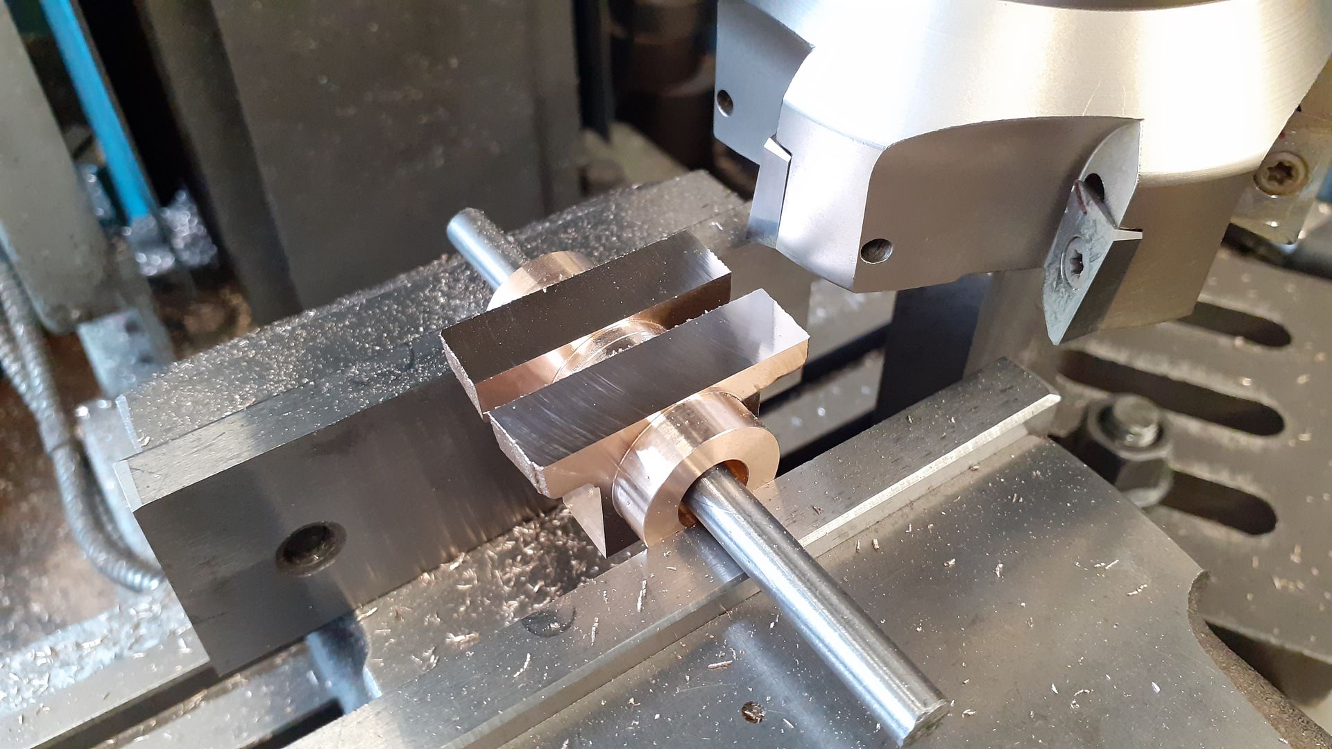
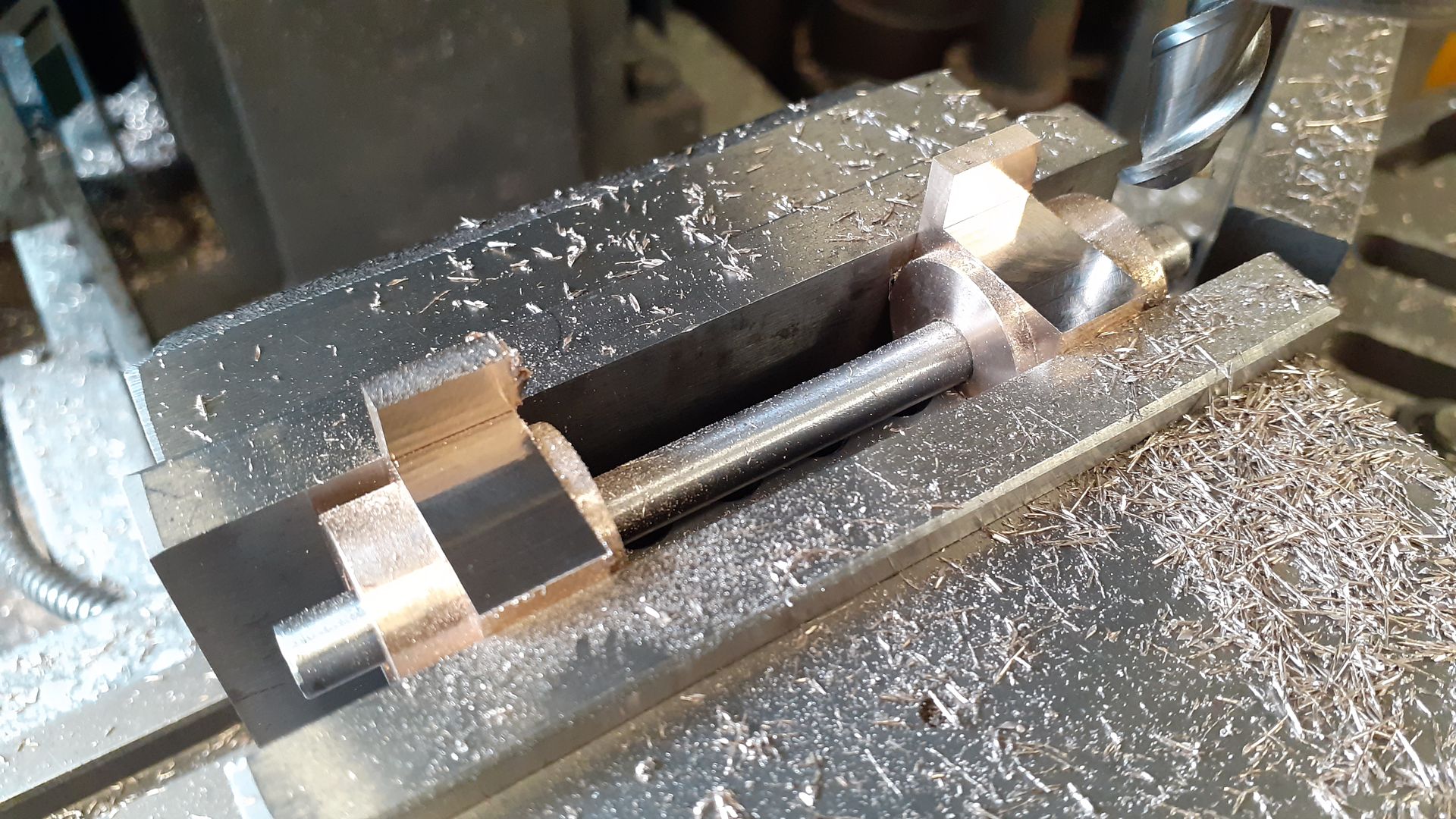
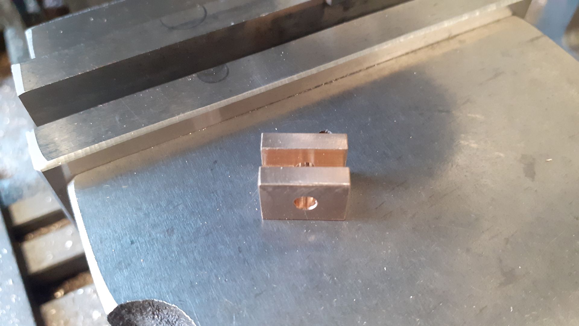
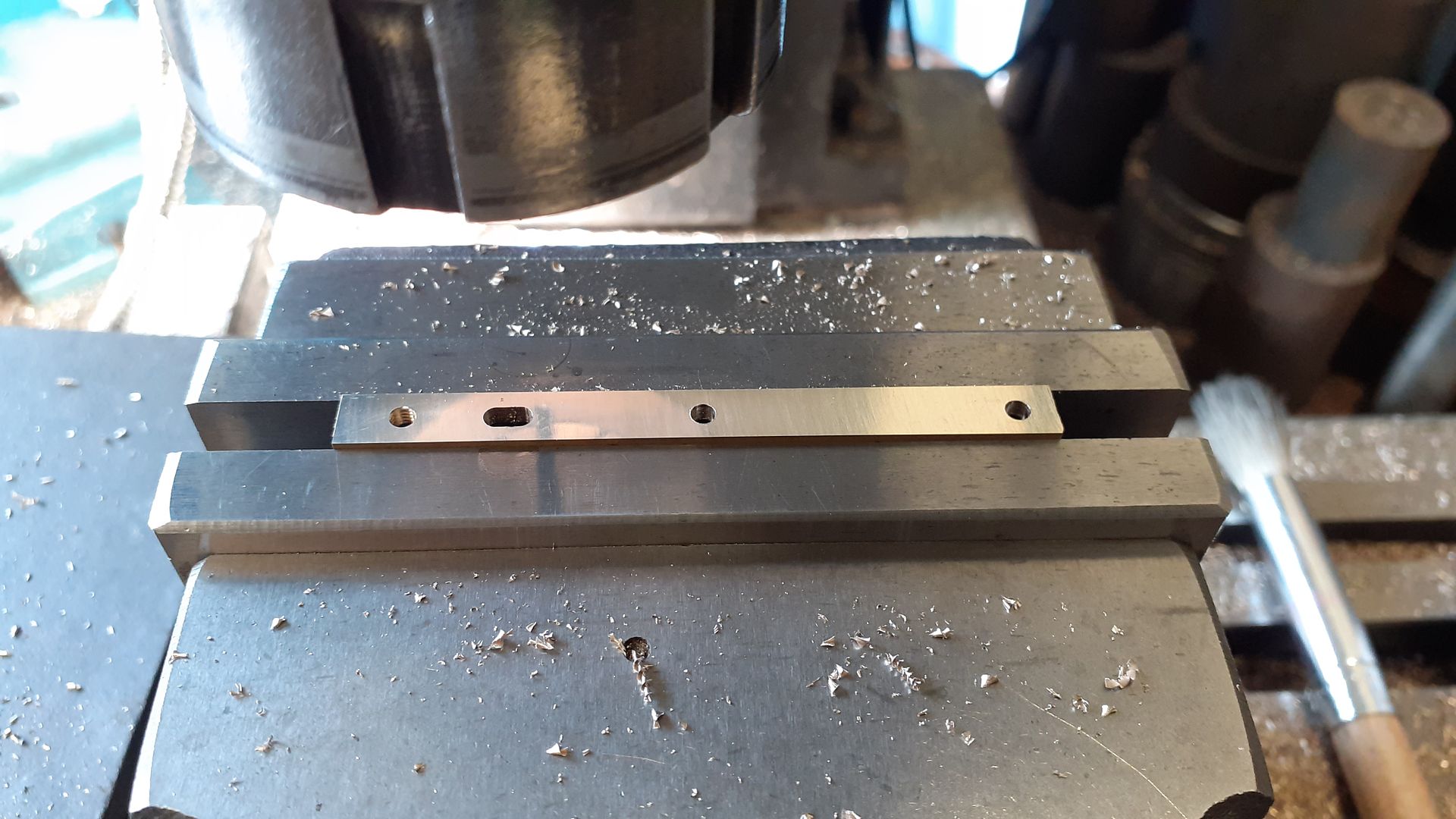
25215 forum posts 3105 photos 1 articles | I decided to start with the two spacers that go between the side plates to get a feel for what the grade of Gunmetal was on some parts that were going to mostly be out of sight. I started by just taking skim cuts off to remove the quite steep draft angles thus giving me some flat surfaces to hold while the 4 long edges were brought down to final size taking similar amounts off opposite faces so that the inverted "T" section stayed central. For almost all the "flat" milling on this engine even the quite small parts I used a 6 insert facemill with APKT inserts which are made for use on non ferrious metals. Most other milling was done with cutters intended for use on Aluminium but they also work well on other non ferrious metal, here you can see a two flute cutter has been used to square up the ends. |
| JasonB | 29/09/2023 19:28:25 |
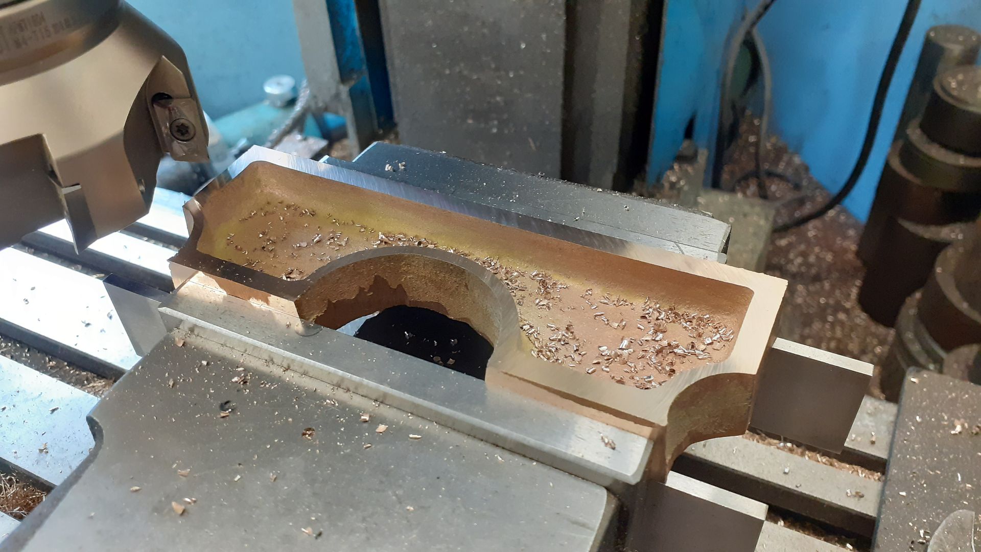
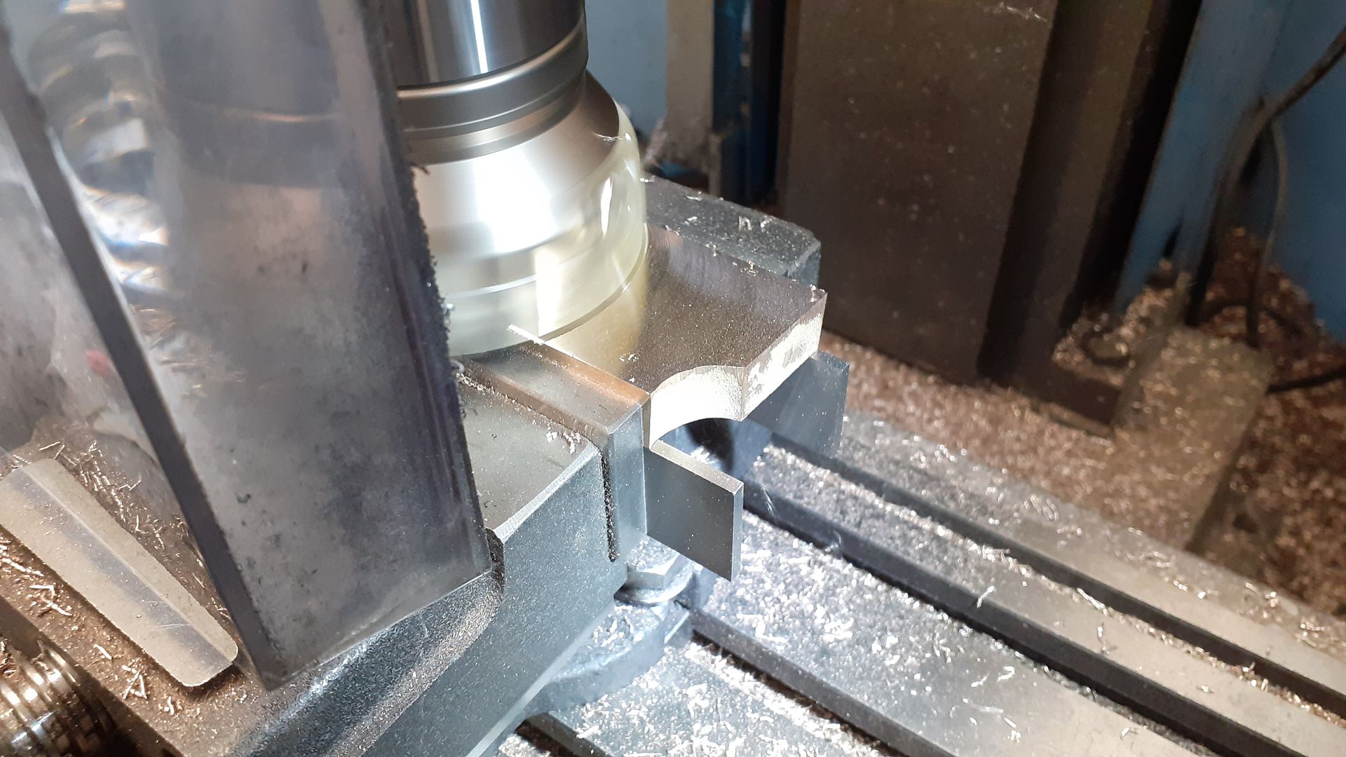
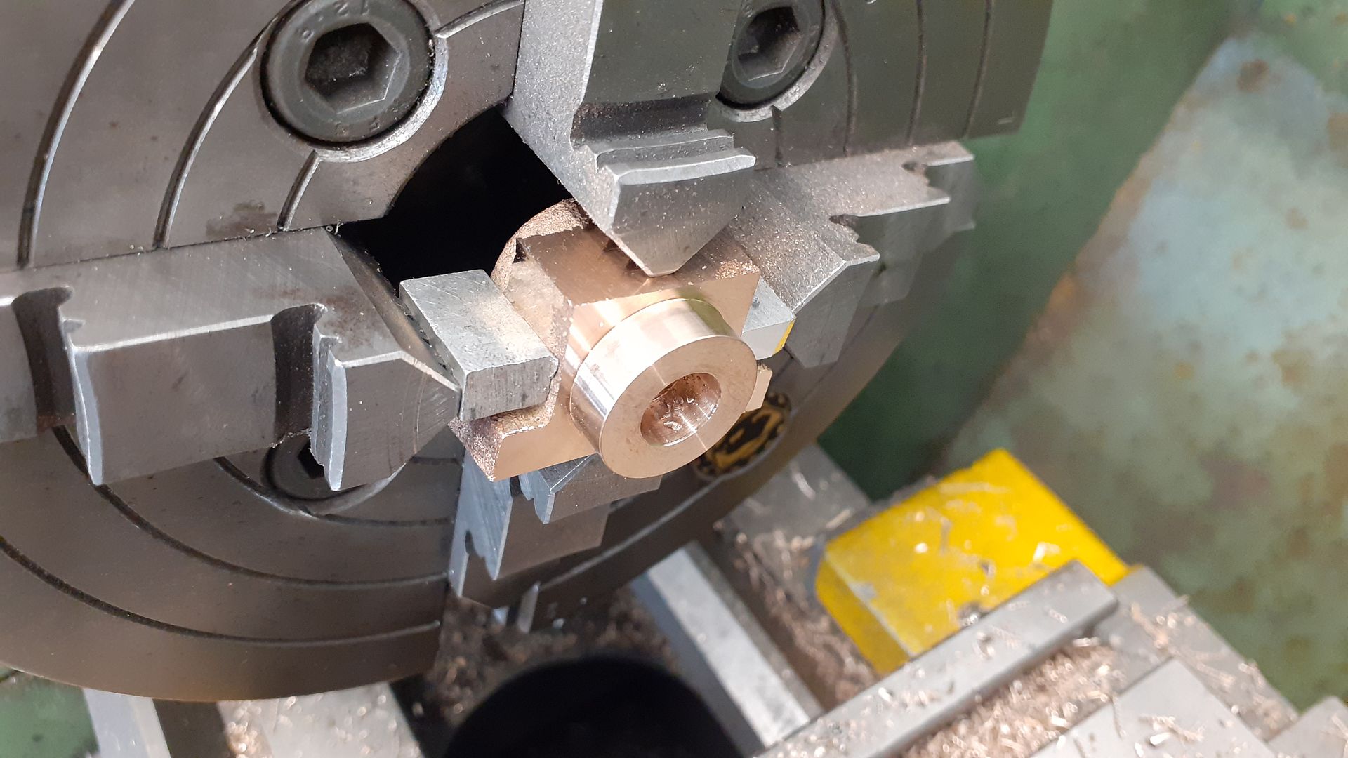
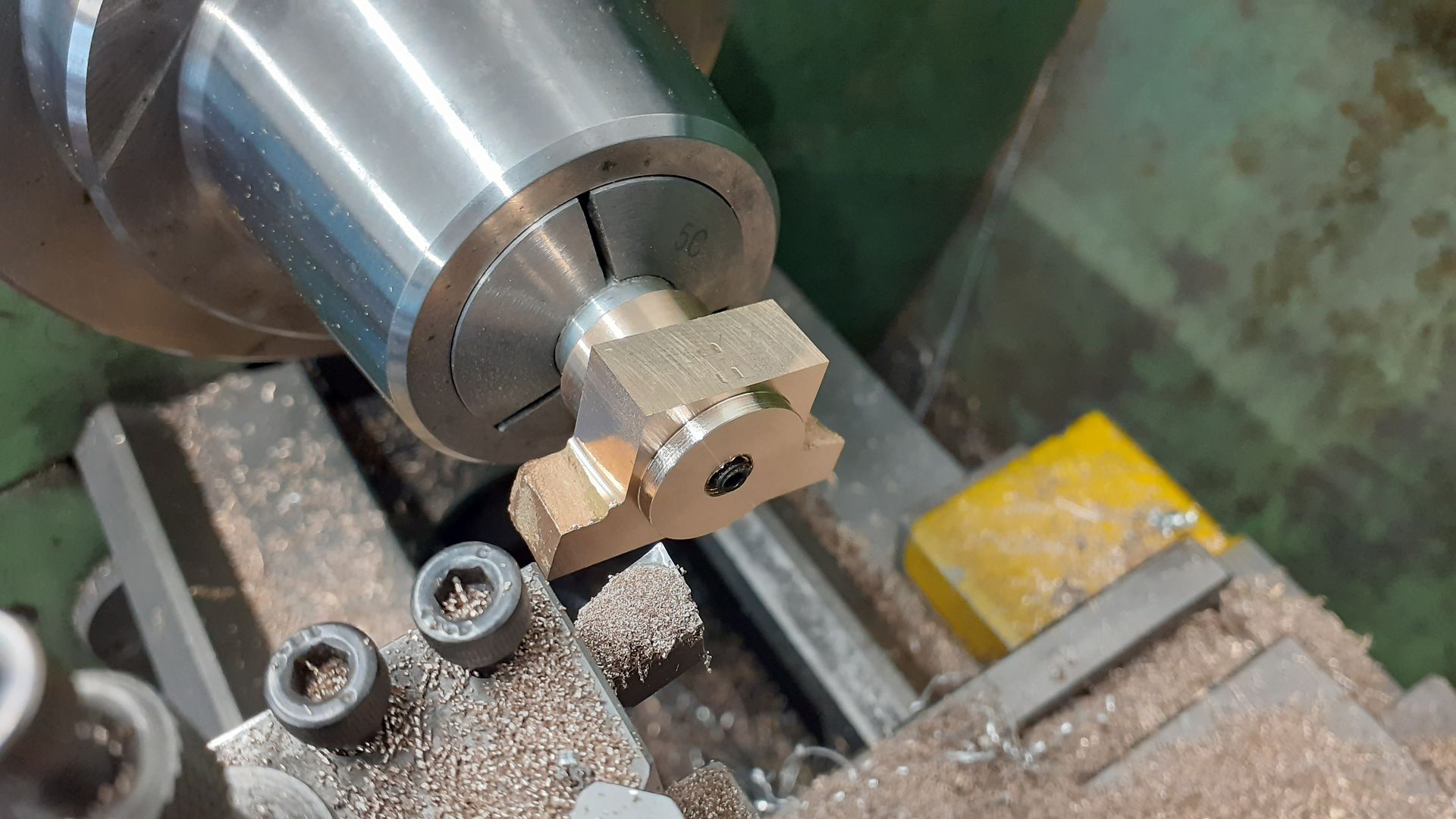
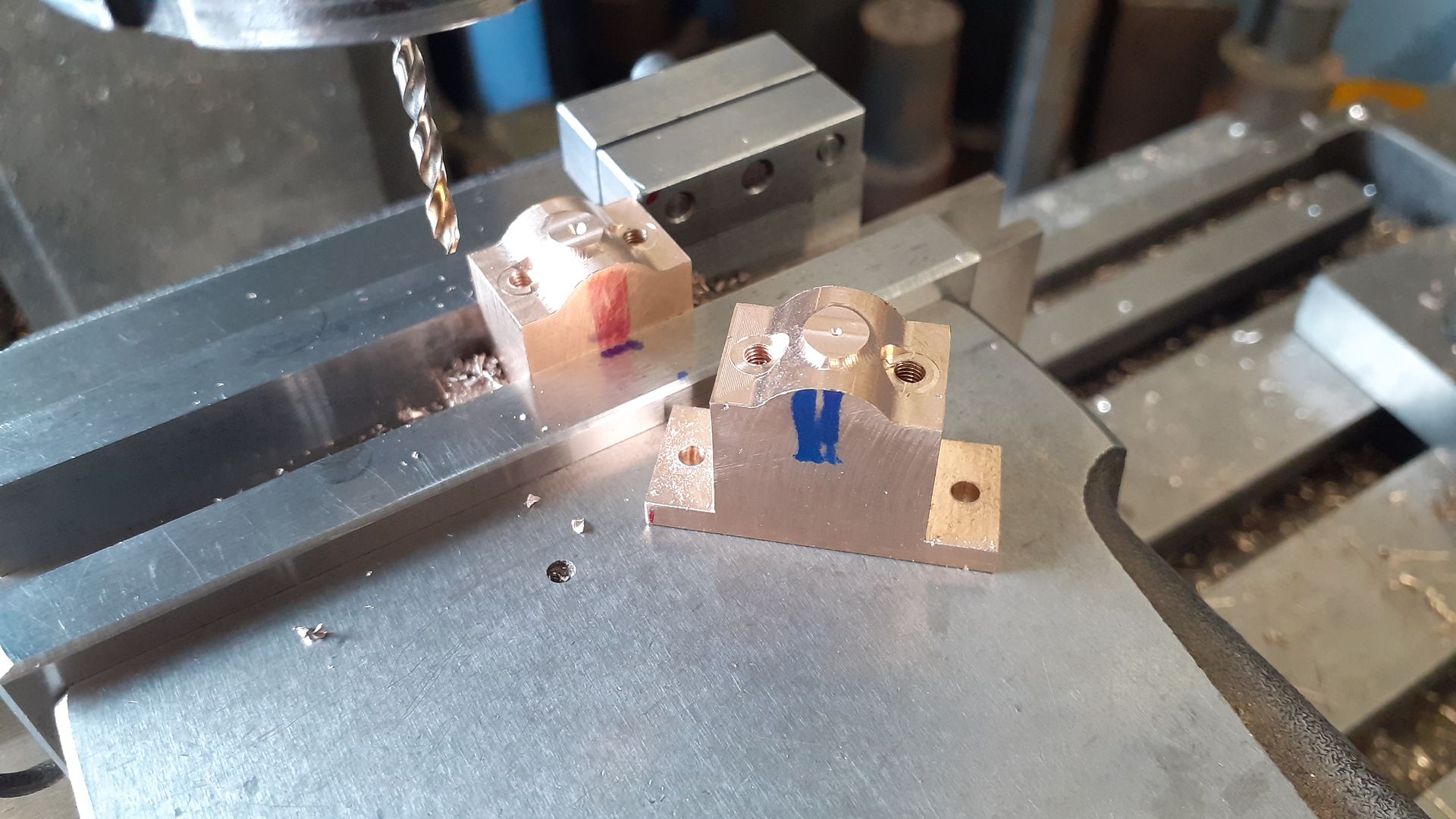
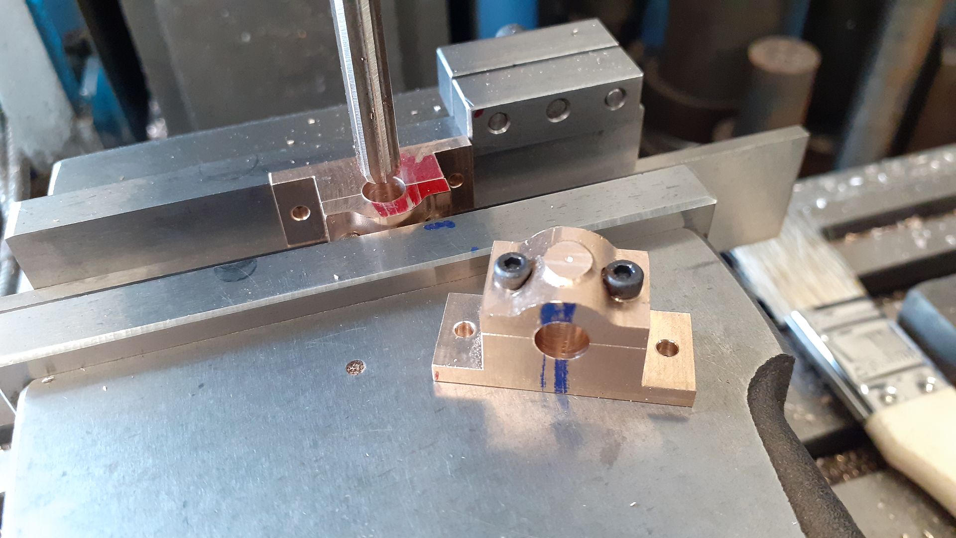
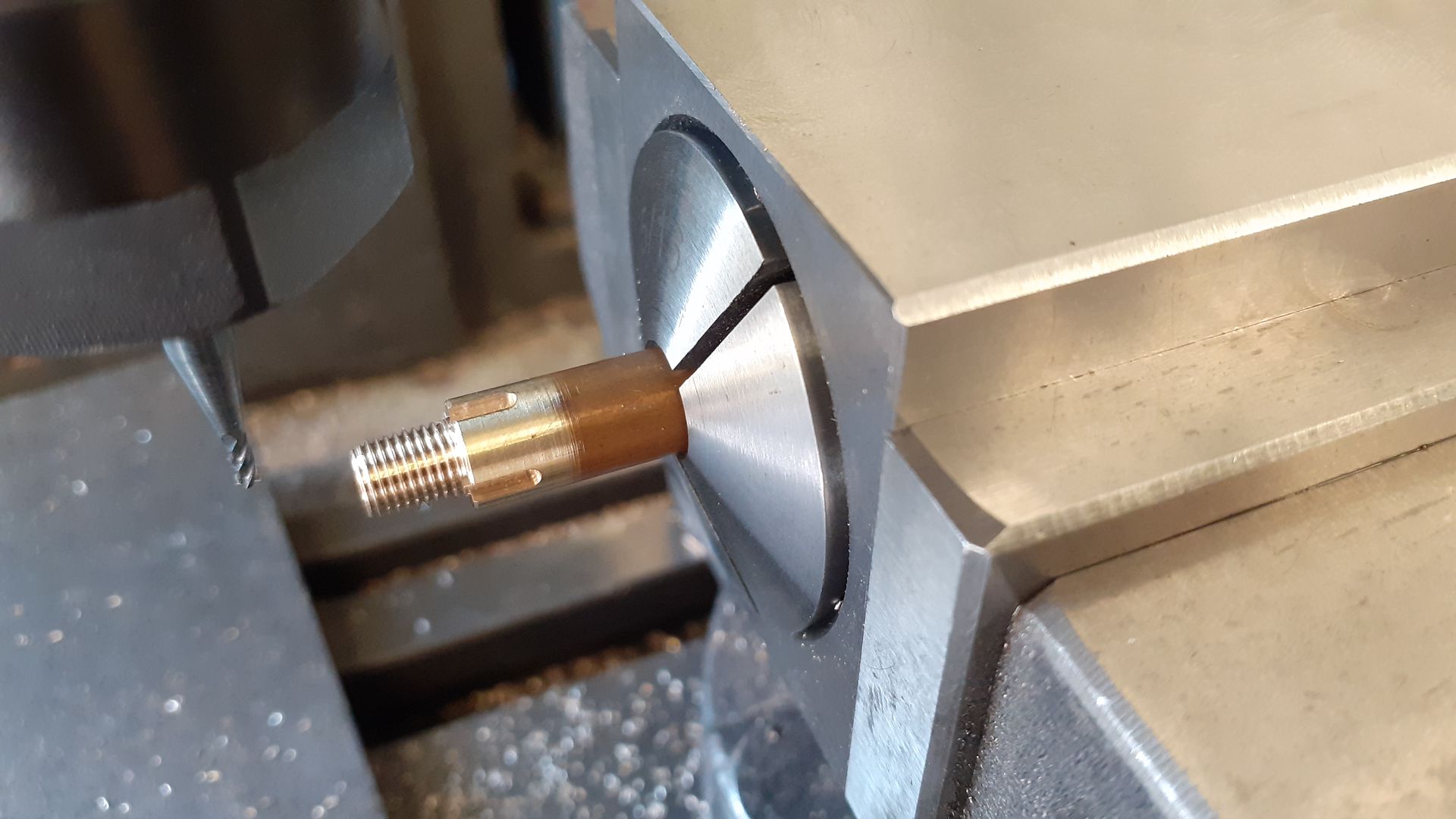
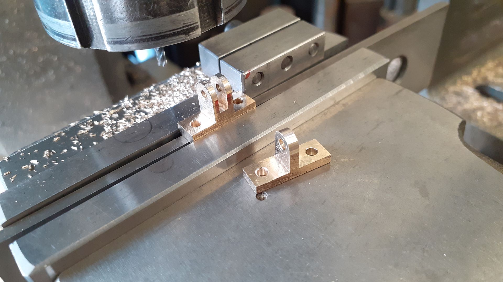
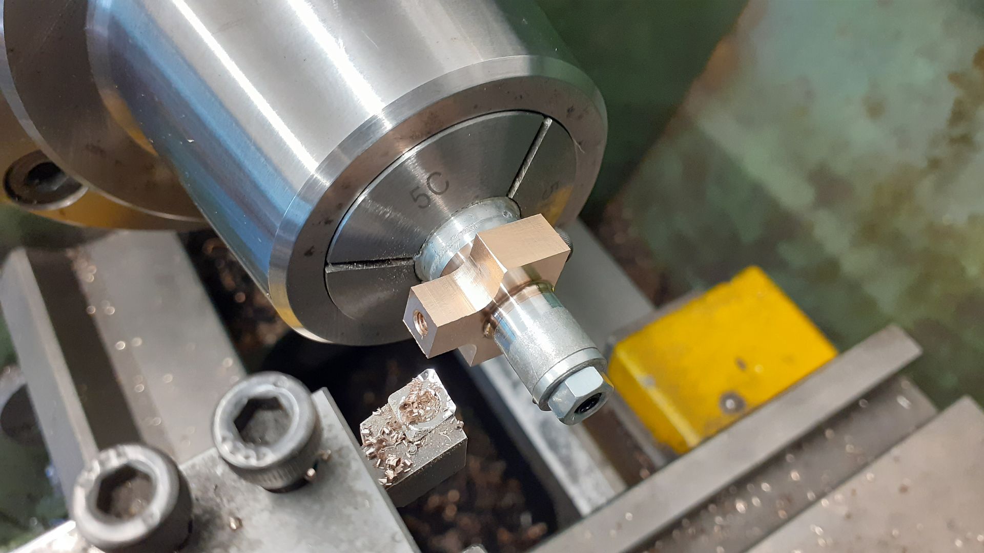
25215 forum posts 3105 photos 1 articles | The cylinder pivots in two trunion bearings, I made a start by skimming the top, bottom and two side to get rid of the draft angle and was then able to close up the chuck jaws on these now flat faces, the sides needed a packer as the foot would have got in the way of the jaws otherwise. The 3/4" dia x 1/4" long outer spigot was turned, a 1/4" hole reamed right through and then counterbored 3/8" for the packing gland. Just like the milling I'm using CCGT polished and ground inserts for non ferrous metal here and did for just about everything lathe operation on this engine. |
| JasonB | 02/10/2023 19:27:59 |
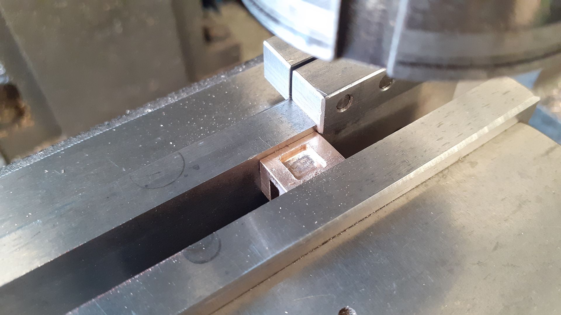
25215 forum posts 3105 photos 1 articles | Rather then do all the big bits and then be left with the small fiddly ones at the end I decided to do a few of those. First was the slide valve for which a small casting is supplied, this was cleaned up all over and then the slot for the valve nut milled. Unlike a lot of valves which have a second slot for the valve rod this one has a hole which is a bit larger than the rod to allow the valve to lift if needed. |


Please login to post a reply.
Magazine Locator
Want the latest issue of Model Engineer or Model Engineers' Workshop? Use our magazine locator links to find your nearest stockist!
Sign up to our Newsletter
Sign up to our newsletter and get a free digital issue.
You can unsubscribe at anytime. View our privacy policy at www.mortons.co.uk/privacy
Latest Forum Posts
- *Oct 2023: FORUM MIGRATION TIMELINE*
05/10/2023 07:57:11 - Making ER11 collet chuck
05/10/2023 07:56:24 - What did you do today? 2023
05/10/2023 07:25:01 - Orrery
05/10/2023 06:00:41 - Wera hand-tools
05/10/2023 05:47:07 - New member
05/10/2023 04:40:11 - Problems with external pot on at1 vfd
05/10/2023 00:06:32 - Drain plug
04/10/2023 23:36:17 - digi phase converter for 10 machines.....
04/10/2023 23:13:48 - Winter Storage Of Locomotives
04/10/2023 21:02:11 - More Latest Posts...
- View All Topics
Support Our Partners


Shopping Partners
Subscription Offer

Latest "For Sale" Ads
- Reeves** - Rebuilt Royal Scot by Martin Evans
by John Broughton
£300.00 - BRITANNIA 5" GAUGE James Perrier
by Jon Seabright 1
£2,500.00 - Drill Grinder - for restoration
by Nigel Graham 2
£0.00 - WARCO WM18 MILLING MACHINE
by Alex Chudley
£1,200.00 - MYFORD SUPER 7 LATHE
by Alex Chudley
£2,000.00 - More "For Sale" Ads...
Latest "Wanted" Ads
- D1-3 backplate
by Michael Horley
Price Not Specified - fixed steady for a Colchester bantam mark1 800
by George Jervis
Price Not Specified - lbsc pansy
by JACK SIDEBOTHAM
Price Not Specified - Pratt Burnerd multifit chuck key.
by Tim Riome
Price Not Specified - BANDSAW BLADE WELDER
by HUGH
Price Not Specified - More "Wanted" Ads...
Get In Touch!
Do you want to contact the Model Engineer and Model Engineers' Workshop team?
You can contact us by phone, mail or email about the magazines including becoming a contributor, submitting reader's letters or making queries about articles. You can also get in touch about this website, advertising or other general issues.
Click THIS LINK for full contact details.
For subscription issues please see THIS LINK.
Digital Back Issues


Donate

 Register
 Log-in
Model Engineer Magazine
- Percival Marshall
- M.E. History
- LittleLEC
- M.E. Clock

ME Workshop
- An Adcock
- & Shipley
- Horizontal
- Mill

Subscribe Now
- Great savings
- Delivered to your door

Pre-order your copy!
- Delivered to your doorstep!
- Free UK delivery!
All Forum Topics > Stationary engines > Digger