
NALON VIPER 2.5 CC DIESEL
I assume that by backing off the compression screw
| KEITH BEAUMONT | 30/08/2023 12:09:10 |
| 213 forum posts 54 photos |
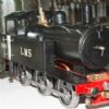
The 4 inlet ports in the cylinder are angled upwards at 25 degrees. No correct information is on the drawing to make sure the exit holes are in the right place and in relation to the 4 exhaust slits. This provided some brain searching regarding hoe to carry out this operation without making a mess of it. I finally decided to ghech 10 time and cut once, by making a dummy cylinder in Ali Slitting the exhausts in the mill and drilling using a solid carbide slot drill in my Dremel, mounted at 25 degrees on my lathe, with cylinder in the indexed chuck. I then cut this cylinder down through its vertical centre, to allow me to accurately measure the relative positions of the drillings inside the cylinder. Fortunately,they wer all spot on, so I repeated the drilling process with the steel cylinder. All parts went togethe without problems. Set up on the test stand with a wooden 9x6" propeller,it started faily easily and was given two x 4 minute rich runs ,with cool down between. No gaskets, no leaks. The third run I over primed and had a back fire or two. Once it had started it would not respond to any adjustments so I stopped it. Compression was not good, so took head and cylinder off to find that the compression screw had punched through the cast iron piston ! I assume that by backing off the compression screw a full turn the contra piston was then slammed onto the screw at the next backfire,causing the cast iron to fail. It is my practice to put a small 45 degree bevel on the end of the compression screw thread, as I have found that lft square the end thread can deform and prevent it being able to be removed from the head if needed. I decided to make the new one in EN1A. Thisis fitted and two more 4 minute runs have taken place since with no problems. I noticed the wood prop had a damaged edge where it had hit my starting stick when it backfired, so these later runsare with an APC nylon 10x4"prop. When I have allowed it to run slightly leaner for a minute it is hovering around 8000 RPM andthe photo of it running is at that speed. I am noticing that this engine is running hotter than other diesels Ihave made. The oil from the exhausts is brown and has that burnt Castor smell. This will possibly diminish as the engine frees up after further running. It will be interesting to see how far I can take this engine,remembering that it was designed as a high performance sport engine of its time.
|
| Emgee | 30/08/2023 12:21:59 |
| 2610 forum posts 312 photos | Keith Could the drag of the bearing seals be causing extra work for the engine which is contributing to the temp rise indicated ? this may be heating the front housing so could be felt after running. Emgee |
| KEITH BEAUMONT | 30/08/2023 14:22:04 |
| 213 forum posts 54 photos | Hi Emgee, I have removed all but the front seal and the front housing stays reasonable. The heat is in the head, but is improving. Sorry about the few typos. I was being called to lunch and was more concerned that the photos were in the right order,due to the need to put them in reverse . What happened to the title I have no idea. It looked OK when I pressed the button. Is it possible for a kind Mod to put that right for me? Keith. |
| KEITH BEAUMONT | 30/08/2023 14:23:31 |
| 213 forum posts 54 photos | Mods. What has happened to the FOR SALE department? Keith |
| Ramon Wilson | 30/08/2023 17:59:34 |
 1655 forum posts 617 photos | Hello Keith, Another nice result and good looking engine. Lovely anodising too Have you hardened the liner or is it stock EN1a ? Reason for asking is that the new contra piston raises the possibility of galling and will be a beggar to remove if it does - just a thought to consider. The original was, I believe, designed to offer an alternative to the Oliver Tiger in T/R so much more than a sport engine I would say so it should have great potential for further running I like to keep the prop pitch down to 4" -5" at most for early runs, 6" provides too much load which can lead to quick heat build up as I'm sure your aware. I have a feeling that it is not a good idea to use identical bearings to support the crankshaft too though cannot think why. I do remember a discussion on this somewhere in the past explaining the reason but having looked cannot find any reference. This would be for an engine with an intended working life I'm sure, can't see that it would make much difference for an ME project. As said though, lovely result, you should be well proud Best - Tug
|
| KEITH BEAUMONT | 30/08/2023 19:53:58 |
| 213 forum posts 54 photos | Hi Tug, Thanks for your appreciative remarks. It is always good to hear from you. Liner is not hardened. I am aware of the possibility of galling,but I gave both the liner and contra a good coating of copper grease when assembling. I have used EN1A for contra pistons on two smaller engines,using copper grease, and they have not seized. Yet.! Machining a stick of 01. 25"diameter cast iron down to less than 0.5" diameter always seems such a waste. I have not heard that it is not good to use identical bearings on a cranshaft, It sounds an interesting point. Surely, on a muti bearing shaft they would keep to the same size. Perhaps someone will come on and explain the technical reason. Thanks again. Keith |
| KEITH BEAUMONT | 30/08/2023 20:15:45 |
| 213 forum posts 54 photos | Thanks for tidying up the title, Mods. Keith |
| DiogenesII | 31/08/2023 06:32:31 |
| 859 forum posts 268 photos | Crank Bearings.. ..Tuig's comment rings a vague bell apropos races having equal numbers of balls at front and back claimed to have the potential to develop a sympathetic / synchronised rotation and produce unwelcome harmonic / loading effects I can't remember the source either..! ..I think advice was to choose bearings from a different range or manufacturer so that if say, the front bearing had seven balls, find an equivalent for the back that had eight.. In any case, I happily defer to vastly more knowledgeable & experienced brains than mine to continue the discussion.... Edit: to correct my poor manners - a very clean and attractive job - nice work! Edited By DiogenesII on 31/08/2023 06:43:54 |
| Ramon Wilson | 31/08/2023 10:16:21 |
1655 forum posts 617 photos | Hi Guys, I think i saw this being discussed some time back on the Barton Control Line Model forum and my memory, vague as it is on recent things, was that it was on similar lines to 'Dio's' comments but as said not completely sure and didn't pay too much attention to it at the time. It was probably in connection with high end motors designed for Team Racing use. I popped a question up last night on there to see if anyone could comment further. Nothing detailed for or against as yet but found it interesting to say the least that three engines I have (ED 2.46 'Racer', Frog 2.49 and the 2.5cc DC Rapier - all diesels) all have same size ball race front and back. Whether they have the same number of balls in each I would have no idea without stripping them down. With the Nalon very similar in layout to the ED Racer I can't imagine any issues with your version Keith but seeing you had mentioned it it rang a bell. What that needs now Keith is a nice Vintage A team race model around it Best - Tug Edited By Ramon Wilson on 31/08/2023 10:17:42 |
| KEITH BEAUMONT | 31/08/2023 10:35:34 |
| 213 forum posts 54 photos | Hi, The thought that it might be something to do with harmonics had occured to me.Whether it is just a theory, or has been known to have a practical result, would be interesting to know. When I have read old AEROMODELLER magazine engine tests by Peter Chinn, of engines with double ball race crankshafts, the ball count of each race was mentioned, rather than the size and I often wondered why, as the reason was not explained, so perhaps it was a well known fact in those days. Keith |
| Neil Lickfold | 01/09/2023 12:55:57 |
| 1025 forum posts 204 photos | The most often cause for the heat build up is not enough clearance in the liner below the ports down to the bottom of the liner. They want around 2 thou or 0.05mm in diameter clearance in that area. The fuel make up can make a difference and overloading the engine with too much pitch or too large a diameter or trying to run too much compression. The piston fit must be good as you have it running. The bearings normally are open for the rear and the front. Rubber shield bearings cause drag and will slow down an engine. The number of balls in a bearing won't make any difference. What does is the shaft to housing clearance, around 0.04mm to 0.05mm on diameter is often used. Often C3 bearings are used to allow for the small shrink fit that is used to keep the bearings in place. Sometimes bearings that are a little tight on the diameters from using standard clearance bearings can increase the friction and then make the lower and front of the housing to be hot. Diesels often run around 45 to 60 c on the bottom of the crankcase, and upto around 170c to 195c on the heads. I have never seen harmonics on bearings ever being an issue in model engines and the number of balls in a bearing being a problem. At some point the ball size , can have an effect on the longevity of the bearings though. Neil
|
| KEITH BEAUMONT | 02/09/2023 20:04:59 |
| 213 forum posts 54 photos | Neil, The mention of the engine runniing hot at that stage was not mentioned as a problem, more as a characteristic of this particular engine. when compared to others. With four angled inlets,it is clearly getting a good charge of fuel per bang. At no time is it over compressed. Now it has had several more minutes of run- in, it is running slightly more cool. I would need a lot of persueding that leaving one rubber seal on the front bearing has any effect on performance whatoever. compared to it s use in keeping any muck out of the bearing.. Keith Edited By KEITH BEAUMONT on 02/09/2023 20:10:14 |
| John MC | 03/09/2023 07:52:14 |
 464 forum posts 72 photos | I would need a lot of persueding that leaving one rubber seal on the front bearing has any effect on performance whatoever. compared to it s use in keeping any muck out of the bearing.. Keith I agree, the friction from an RS built in type seal is, for all practical purpose, zero. As you say, retaining the outer facing seal is useful for keeping the muck out. You referred to a discussion of a few years ago about the poor bearing mounting arrangements in this engine, how did you go about correcting this? Interested to know because I was involved in that discussion. Its been a few years since I ran my version of this engine, might try and resurrect it! The only problem it had was the contra-piston tightened up in the cylinder, needed correcting a few times. Probably heat related, the only time it happened was when the engine was run "in anger" under the bonnet of a tethered car.
|
| KEITH BEAUMONT | 03/09/2023 17:12:22 |
| 213 forum posts 54 photos | John, Most of the mods I carried out are mentioned in the original post, other than I machined 0.025" clearance for the inner bearings to clear the front housing and I put same dimention clearance on the con rod face to crankshaft. Cooling in a tethered car is not as efficient as a prop in front,so perhaps it did heat up somewhat. How did you correct it? Keith. |
| Roy Vaughn | 03/09/2023 23:03:44 |
| 70 forum posts 4 photos | I think the main reason for using bearings of different size is to make it easier to maintain the spacing of the inner bearing rings. Without a stepped shaft the front inner will be prone to moving around unless it's an interference fit on the shaft or there is a separate spacer to set the distance as in the FMV. The Viper was intended as a competition engine so this might have been a consideration. Mine manages 14,400 on an APC 8x4 on 20% castor fuel, I'd be interested to hear how yours performs. Roy |
| John MC | 04/09/2023 09:09:53 |
464 forum posts 72 photos | Posted by KEITH BEAUMONT on 03/09/2023 17:12:22:
Cooling in a tethered car is not as efficient as a prop in front,so perhaps it did heat up somewhat. How did you correct it? Keith. I didn't get it fully sorted. Removed the contra-piston, fortunately no galling, polished it, reassembled and and ran it. My first thought was incompatible metals. Cylinder and piston both cast iron from an unknown source, different expansion rates? Would account for one tightening up, but 4 - 5?
|
| KEITH BEAUMONT | 04/09/2023 14:48:53 |
| 213 forum posts 54 photos | John, When you mentioned that you were part of the previous long discussion, I decided to read it all again, but did not think a deffinate result came of it.. My simple thought about fitting ball races is that the outside and the inside diameters need restraining for the shaft to rotate properly I use the same system as Tug Wilson with the first bearing. Put the bearing on the crankshaft first, heat the crankcase and drop the shaft and bearing into the case. I have previously made honed test pieces to determine the restrained fit for the inner diameter. This is 0.0005" larger diameter than the shaft, so I hone the shaft to give this restraint and I find it works for me. My cylinder is EN1A with CI piston,as I used the original design drawings. Dated15/12 /15. I also made the crank web the full thickness 0.160" aand lightened it by removing two scallops either side of the pressed in crank pin. Roy, As the front bearing does most of the work,i have always thought that having a smaller front bearing was more to do with trying to be lighter,rather than for some technical reason. 14,400 RPM sounds impressive to me and I will be quite happy to avhieve similar. At the moment I am still having short , mostly rich runs and am just hovering around 10,000 RPM. When I pinch of the fuel tube to stop it, I get a burst of high revs, so we are not there yet. I will come back with more progress later. The fastest engine in my collection engine is one I was given and no one has been able to identify. It is a Glow, about 4cc.beautifly made with a real deflector on piston head, with matching space in cylinder head. It will rev at 16,000 with a 10x4" prop, but has only a plain Ali bearing in the case. The front housing is Ali too but has been bushed with another type of Ali. Can be seen in my Album. in the Vee twin photos. Has black, steel integral fins. Probably a prototype from somewhere. Keith. |
| Ramon Wilson | 04/09/2023 16:05:14 |
1655 forum posts 617 photos | Hello Keith, Like you I felt the need to reread the old thread again and without going all over it again I remain unchanged in my thoughts as to seating the bearings - in a home made engine of this kind - though of course many commercial TBR engines have the same situation. With regard to the same size bearings - the jury seems to be out on this over at the Barton site. No one has recalled the discussion I thought had taken place on there though of course that doesn't mean it wasn't. There is some mention of potential harmonics but nothing fact based and many pointing out that same size bearings are okay. I wish I could remember where I saw it but I can't and anyway at our level it doesn't seem to matter. Why I prefer the larger rear bearing (which takes the radial loads) and a smaller front bearing which takes the axial ones is mainly due to the ease of ensuring the inner race at the front is firmly nipped between the step on the shaft and the prop driver collet when the prop is tightened. That it may have some potential increase in performance (over same size bearings) has never been in my thoughts and as we've all been there before theres no point in repetition of discussion I guess. Heat build up in the cylinder is to be expected on bench running and indeed inside a closely cowled 'bonnet'. Running in will soon produce heat, so fast, but not leaned out, short runs are better than long rich ones not allowing the heat to build to rapidly and allowing the engine to cool before repeating. A fine pitch prop say 4" or less will allow the engine to 'run' without placing too much load on it - 6" pitch or more is not ideal as even with a smaller diameter the load is more than what is ideal at the early stage of running. A cast piston in a cast liner is a good combination material wise (though not the best) but even the best of initial compression will ease as the surfaces wear quite quickly on those early runs with the oily black exhaust residue giving clear indication. If the parts are unhardened then the best combination is that recommended by that long ceased engine 'guru' George Aldrich - a Meehanite or (continuous cast) piston in free cutting steel making the contra piston from the same cast. With regard to seals - I do use sealed bearings if open ones aren't available but always remove the seals before fitting. If that front bearing becomes gummed with castor it's much easier to free with a drop of cellulose behind the prop driver - difficult with a seal fitted. All this engine talk is whetting my appetite but fortunately(?) the workshop isn't up and running as we speak. I do have the need for a good 3.5cc for a team race model - a bored out Viper might just be worth considering. All the best for that next project Tug Edited By Ramon Wilson on 04/09/2023 16:08:59 |
| KEITH BEAUMONT | 04/09/2023 21:03:12 |
| 213 forum posts 54 photos | Hi Tug, Re-capping on this engine information made me realise that I have two different sets of drawings for it,all with the same date,other than Sheet 8 the revised Cylinder/Head drawing, which is dated 18/12/2011, the others all being dated14/12.2011or 15/12/2011 I had been interested in this engine for a few years and had previously printed a set and forgot about it... The Crankshaft , Sheet 2 has two designs. One has a plain circular web, with no relief for bearing or con-rod.. The other is radialy lightened,with relief for con-rod,but not for the bearing.Same date, 15/12/2011. Sheet 4, Cylinder, has different size for sliiting saw to be used for Exhaust slots. One is 3/16", one is 3/32". This one does have a note mentioning change of saw and lowering the port and flange top by 0.022"to allow for the change of slitting saw. Both have same date. this time 14/12/2011. Sheet 3, Backplate,has different centre measurements for the Inlet, differing by 0.015" vertical and 0.055" horizontal, which will alter the timing. 15/12/2011 for both. Sheet 5 Contra piston has a completely different shape. It therefore looks like two different engines can be made from what looks like the same Drawings. Three if you count the the revised sheet six, withe the integral fins and larger modified shape ,inlet ports. I find it odd that Eric Offen, who produceed the drawings using the same dates, has not clearly stated that two versions exist It would be interesting to hear what versions have been made. Which mix did you use in the one you made? Keith. |
| Ramon Wilson | 05/09/2023 11:06:58 |
1655 forum posts 617 photos | Hi Keith, I have now disposed of my hard copies of the various drawings the only ones I have being PDFs on file. These were updated to the 24-12-2011. The 3/16 port depth on previous issues was a typo. The port height is 3/32 (.092) and the 3/16 is the width of port with the cutter at correct depth. My drawing shows an unusual heavily tapered top piston with a recessed contra piston to match. The CP is bored from the top the recess being .100" deep with the land between top and bottom recess apx ..090. Were I to make one I think I would be inclined to make the piston flat topped but this of course would mean rearranging the port heights to suit the desired timing. I only got as far as making the cases on my intention for 5cc versions I'm afraid. I may be wrong but I believe Ron Chernich did the actual drawings from information provided by Eric te style is certainly Ron's As you comment, quite a few have been made - far more than the prototypes for sure. I don't know why an all cast liner/cylinder was seen as a potential advantage - heavier of course than the conventional set up. It should be borne in mind that the original was specifically destined to be used in Team Race etc. as an alternative to the growing dominance of the Oliver Tiger so any increase in weight is a disadvantage to my mind. I don't know if anyone has built that version - as you say it would be interesting to hear from them if so. All of this is not good for my peace of mind
Best - Tug Edited By Ramon Wilson on 05/09/2023 11:08:33 |


Please login to post a reply.
Want the latest issue of Model Engineer or Model Engineers' Workshop? Use our magazine locator links to find your nearest stockist!
Sign up to our newsletter and get a free digital issue.
You can unsubscribe at anytime. View our privacy policy at www.mortons.co.uk/privacy
- *Oct 2023: FORUM MIGRATION TIMELINE*
05/10/2023 07:57:11 - Making ER11 collet chuck
05/10/2023 07:56:24 - What did you do today? 2023
05/10/2023 07:25:01 - Orrery
05/10/2023 06:00:41 - Wera hand-tools
05/10/2023 05:47:07 - New member
05/10/2023 04:40:11 - Problems with external pot on at1 vfd
05/10/2023 00:06:32 - Drain plug
04/10/2023 23:36:17 - digi phase converter for 10 machines.....
04/10/2023 23:13:48 - Winter Storage Of Locomotives
04/10/2023 21:02:11 - More Latest Posts...
- View All Topics


- Reeves** - Rebuilt Royal Scot by Martin Evans
by John Broughton
£300.00 - BRITANNIA 5" GAUGE James Perrier
by Jon Seabright 1
£2,500.00 - Drill Grinder - for restoration
by Nigel Graham 2
£0.00 - WARCO WM18 MILLING MACHINE
by Alex Chudley
£1,200.00 - MYFORD SUPER 7 LATHE
by Alex Chudley
£2,000.00 - More "For Sale" Ads...
- D1-3 backplate
by Michael Horley
Price Not Specified - fixed steady for a Colchester bantam mark1 800
by George Jervis
Price Not Specified - lbsc pansy
by JACK SIDEBOTHAM
Price Not Specified - Pratt Burnerd multifit chuck key.
by Tim Riome
Price Not Specified - BANDSAW BLADE WELDER
by HUGH
Price Not Specified - More "Wanted" Ads...
Do you want to contact the Model Engineer and Model Engineers' Workshop team?
You can contact us by phone, mail or email about the magazines including becoming a contributor, submitting reader's letters or making queries about articles. You can also get in touch about this website, advertising or other general issues.
Click THIS LINK for full contact details.
For subscription issues please see THIS LINK.


 Register
 Log-in
Model Engineer Magazine
- Percival Marshall
- M.E. History
- LittleLEC
- M.E. Clock

ME Workshop
- An Adcock
- & Shipley
- Horizontal
- Mill

Subscribe Now
- Great savings
- Delivered to your door

Pre-order your copy!
- Delivered to your doorstep!
- Free UK delivery!