Forum sponsored by:

Boll aero 18 internet drawings
Ron Chernich drawings
| geoff walker 1 | 30/04/2023 10:47:59 |
| 521 forum posts 217 photos | HI all, I'm looking to make a start on this engine, but before I do an enquiry about the Ron Chernich drawings on the internet. I have many questions about this engine and the drawings which I will ask in due course. For now though just one about Ron's drawings. Are these drawings generally speaking "good to go" i.e. no major issues or omissions. Any comments most welcome. Geoff |
| Ramon Wilson | 30/04/2023 11:10:15 |
 1655 forum posts 617 photos | Hi Geoff, Like any drawings - including my own - and despite best efforts on the part of the draughtsman mistakes can, do and will happen. Ron's drawings were usually pretty good overall though as said you may find the odd anomaly here and there. There's been many Boll Aero's made overtime - I don't recall hearing of anything that will prevent you making a good example - good luck with it
Tug |
| JasonB | 30/04/2023 13:04:44 |
 25215 forum posts 3105 photos 1 articles | You could always PM Chris Boll, he is a member. |
| DiogenesII | 30/04/2023 20:12:18 |
| 859 forum posts 268 photos | I used those same drawings to build mine and don't recall having any real issues, it was fun to do and in spite of being my first experience of any kind with CI engines was quite easy to get going and (still is) a nice runner.
|
| geoff walker 1 | 01/05/2023 17:36:01 |
| 521 forum posts 217 photos | Hi Gents, Thank you for your replies. My gut feeling was that Ron's drawings would be reliable, but nice to have that confirmed I'll keep posting on this thread with progress as I go along and of course I will have many questions. Thanks again Geoff Not sure about some of the "americanisms" on Ron's drawings. A cylinder MUFF, MUFF? MY Nan used a muff and I muffed a lot catches playing cricket, but an engine part!!!!!! |
| geoff walker 1 | 19/07/2023 11:51:54 |
| 521 forum posts 217 photos | Hi All Well I'm making a start on this engine, so more questions to come. I' intend to do all the machining on the sherline lathe which is fine for most of the parts. I decided to bore out the crankcase using the four jaw chuck. The length of the case was I thought a problem as supporting the work would be difficult. I therefore decided to to split the case into a lower and upper half to make the machining more manageable. The lower half has a recess to accept a register ring on the upper half.
I'll need longer head bolts as the threaded anchor points will be in the lower half of the case with clearance holes in the upper half. The register is a very snug fit but I still plan to silicone seal the joint on assembly. More post in due course hope this is of interest Geoff |
| Ady1 | 19/07/2023 13:43:32 |
 6137 forum posts 893 photos | Ron was a cool guy and is missed |
| geoff walker 1 | 23/07/2023 11:45:41 |
| 521 forum posts 217 photos | Hi All, Ron's drawings show three options for the crankshaft. This is one of them which I believe is Chris Boll's original design.
I like this one and will probably use it. Ron points out that using this design "may" result in a "thrown prop". What is a thrown prop? With particular reference to this engine has anyone any ideas how this design may result in a thrown prop. I'm just curious, the design seems sound to me but perhaps I'm missing something? Geoff |
| Ramon Wilson | 23/07/2023 12:04:20 |
1655 forum posts 617 photos | Hello Geoff, A 'thrown prop' is when the prop becomes loose - usually when flicking to start it. The engine comes up on compression and the force loosens the prop nut. For the most part it's just a matter of retightening it but if it occurs a lot it's best to redesign the prop driver to something more practical. Some commercial engine shafts have straight knurling with the prop diver forced on, others a slotted drive but the easiest to make and sound in design is the tapered brass collet in a taper bored prop driver - the taper needs to be an exact match though for optimum drive. It is said that throwing a prop can lead to the engine having a shaft run - ie the prop coming off and the engine continuing to run totally unloaded but having hand started engines for so many years and throwing props on many occasions I've yet to experience that happening. Indeed in 65 years of playing with diesels I've yet to meet anyone who has! I have some pics of the taper collet system so I will upload them for you
Best - Tug Edited By Ramon Wilson on 23/07/2023 12:17:22 |
| Ramon Wilson | 23/07/2023 12:26:24 |
1655 forum posts 617 photos | Geoff - here are six pics from my ETA build described on MEM (I think)
Boring the prop driver blank with the topslide set at the required angle
Reverse turning a taper mandrel with the topslide unmoved
Holding the blanks on the mandrel to knurl the front face
Revers turning the brass collet
Parting the collet off leaving a small step
Finished items. The collet must bear against a shoulder on the crank shaft to resist the tightening forces. The step cut in the rear face of the collet is to enable a small lever to prise it off. No step - very difficult!
Hope that helps
Tug Edited By Ramon Wilson on 23/07/2023 12:27:32 |
| geoff walker 1 | 23/07/2023 12:29:37 |
| 521 forum posts 217 photos | Hi Tug, Thanks for your reply. I can see how a collet driver will be locked very tight on the shaft. If the driver is not REALLY secure on the shaft then it may shift marginally and loosen the nut. Does that make sense? In the design above the driver is screwed onto the shaft and then presumably it locks in place when it butts up against the end of the shaft, but perhaps not secure enough to prevent it coming free and loosening the nut. After your comments I'll look at the collet option in Ron's drawing Thanks again Geoff Good project this I'm enjoying it!! Edited By geoff walker 1 on 23/07/2023 12:42:02 |
| geoff walker 1 | 23/07/2023 12:32:04 |
| 521 forum posts 217 photos | Hi Again Tug, Just seen the pictures. Excellent thanks Geoff |
| KEITH BEAUMONT | 23/07/2023 12:33:29 |
| 213 forum posts 54 photos | Well; Tug I can make your day! A few years ago, when I was test running the Sparey 5cc Diesel, I had just such an accurance. Engine back fired on start up, Prop spun off, but engine continued to run without the prop,but clockwise. I stopped it by shutting the needlle valve. I had not heard of such a possibility and like you have no knowledge of anyone else having it happen. The Boll-Aero 1.8 drawings have no problems. I made the crankshaft to accept the collet /driver/ Keith |
| Ramon Wilson | 23/07/2023 12:50:26 |
1655 forum posts 617 photos | Well how about that Keith - on a side port engine too!. The only time I saw - more like heard - a shaft run was at a Nats when a speed model clipped the deck shearing both prop blades - the instantaneous increase in revs was something to be witnessed but no, never heard of one occurring when being started. There is a well know pic of someone starting a control line aerobatic model at a major competition the camera capturing the exact moment the prop is spinning off the engine shaft about 2 inches in front of the model and the revolutions caught in three distinct turns in front of the person starting it Geoff - if you are able to incorporate it the tapered collet system is the best of all allowing tight grip but easy removal. The angle wants to be 15 - 20 degrees (30 to 40 inclusive) too fine and it can lock. Don't make the collet from ali as it will in all probability gall and bind solid Keep on enjoying yourself Tug |
| geoff walker 1 | 26/07/2023 16:10:17 |
| 521 forum posts 217 photos | Some more progress today. After some initial milling, shaping and drilling, set up the con rod on the Sherline. Perfect for the smaller items. Last photo shows it alongside the head, finished after some nibbling on the mill and some judicious filing.
Geoff |
| geoff walker 1 | 26/07/2023 16:14:38 |
| 521 forum posts 217 photos | When I made the "firefly" some years ago I used EN8M for the crankshaft and the cylinder liner. I assume that the same will be ok for this engine but of course I am open as always to advice. I will need to place an order soon from M metals. Geoff |
| Ramon Wilson | 26/07/2023 17:41:53 |
1655 forum posts 617 photos | Hi Geoff, I've only ever used En24t for the cranks in my attempts but they are much larger of course. I would think En8M would be fine. With a cast iron piston the best material for an unhardened liner is plain old leaded mild steel (FC En1a). Easier to machine to a fine finish, laps well and is a great running combination with CI. I made eighteen scaled up 5cc diesel engines in total, the first had a cast liner and though still good compression after running it soon lost that 'firmness' of the initial set up. The second had a liner made from a tough steel (CR8) which proved very testing machining the ports with home made tooling. I then read an article about using 'cast in steel' as a set up for diesel or glow engines using leaded mild steel and made all the others in that fashion. None were hardened (by case hardening) and all proved to give excellent and lasting compression. (You should try hand flicking one of the Hunters Again nothing wrong with using EN8 - just wouldn't use it myself. Hope you've got plenty of fuel - it's getting harder to source these days and quite expensive for what it is.
Best - Tug |
| geoff walker 1 | 29/08/2023 16:26:20 |
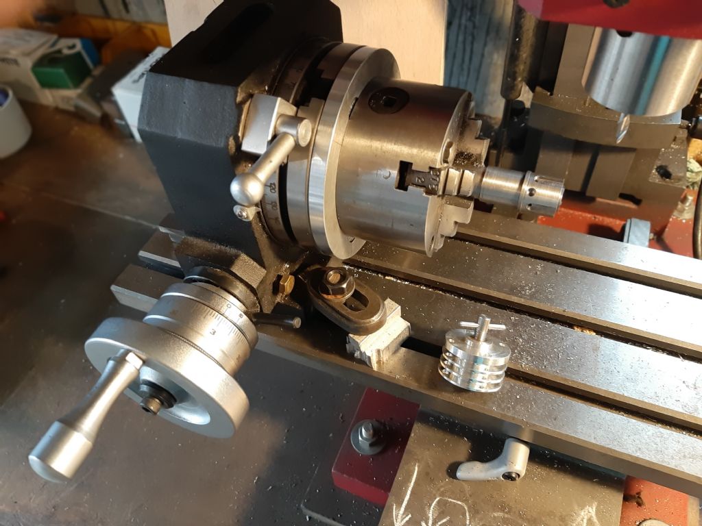
| 521 forum posts 217 photos | I bought this rotary table about 4 years ago. I had to tweak it a little before the first use but since then it's had lots of use and I've been really pleased with it. I added a circular alloy table to make it easier to mount chucks and other attachments. The chuck in the picture is an Indian Zither, bought from ARC, again about 4 years. 4 jaw self centring, very accurate and for the price I paid good value. Both seen here in use milling the transfer channels and drilling the port holes in the Boll Aero cylinder. The cylinder is made from EN1A mild steel.
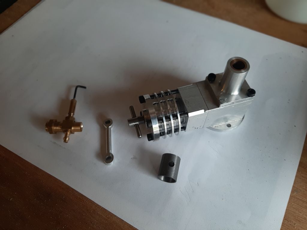
Progress has been ok, here is another picture of some completed parts.
The cylinder head screw for adjusting the contra piston is made to the sizes in Ron's drawings. I have seen some engines like this one which have a locking lever on the head presumably to secure the position of the screw and the optimum compression position for the contra piston. My feeling is that the lever is a good addition as when the engine is running (if the engine runs!!!!) there may be a possibility that the screw may vibrate loose and lose the setting? Any thoughts. Geoff |
| KEITH BEAUMONT | 29/08/2023 20:08:07 |
| 213 forum posts 54 photos | Hi Geoff, It really depends on whether you are going to put the engine in a model that will fly. If so, it might be a good idea to be able to lock the compression, but if you are just going to run it on a test stand, I personally would not bother. You will be adjusting compression as you enjoy hearing it run. Keith. |
| geoff walker 1 | 29/08/2023 20:30:43 |
| 521 forum posts 217 photos | Hi Keith, Thanks for the reply. I think it's unlikely to go airborne, maybe, ...but unlikely. So I'll leave it as it is for now Thanks Geoff |
.jpg")
.jpg")


Please login to post a reply.
Magazine Locator
Want the latest issue of Model Engineer or Model Engineers' Workshop? Use our magazine locator links to find your nearest stockist!
Sign up to our Newsletter
Sign up to our newsletter and get a free digital issue.
You can unsubscribe at anytime. View our privacy policy at www.mortons.co.uk/privacy
Latest Forum Posts
- *Oct 2023: FORUM MIGRATION TIMELINE*
05/10/2023 07:57:11 - Making ER11 collet chuck
05/10/2023 07:56:24 - What did you do today? 2023
05/10/2023 07:25:01 - Orrery
05/10/2023 06:00:41 - Wera hand-tools
05/10/2023 05:47:07 - New member
05/10/2023 04:40:11 - Problems with external pot on at1 vfd
05/10/2023 00:06:32 - Drain plug
04/10/2023 23:36:17 - digi phase converter for 10 machines.....
04/10/2023 23:13:48 - Winter Storage Of Locomotives
04/10/2023 21:02:11 - More Latest Posts...
- View All Topics
Support Our Partners


Shopping Partners
Subscription Offer

Latest "For Sale" Ads
- Reeves** - Rebuilt Royal Scot by Martin Evans
by John Broughton
£300.00 - BRITANNIA 5" GAUGE James Perrier
by Jon Seabright 1
£2,500.00 - Drill Grinder - for restoration
by Nigel Graham 2
£0.00 - WARCO WM18 MILLING MACHINE
by Alex Chudley
£1,200.00 - MYFORD SUPER 7 LATHE
by Alex Chudley
£2,000.00 - More "For Sale" Ads...
Latest "Wanted" Ads
- D1-3 backplate
by Michael Horley
Price Not Specified - fixed steady for a Colchester bantam mark1 800
by George Jervis
Price Not Specified - lbsc pansy
by JACK SIDEBOTHAM
Price Not Specified - Pratt Burnerd multifit chuck key.
by Tim Riome
Price Not Specified - BANDSAW BLADE WELDER
by HUGH
Price Not Specified - More "Wanted" Ads...
Get In Touch!
Do you want to contact the Model Engineer and Model Engineers' Workshop team?
You can contact us by phone, mail or email about the magazines including becoming a contributor, submitting reader's letters or making queries about articles. You can also get in touch about this website, advertising or other general issues.
Click THIS LINK for full contact details.
For subscription issues please see THIS LINK.
Digital Back Issues


Donate

 Register
 Log-in
Model Engineer Magazine
- Percival Marshall
- M.E. History
- LittleLEC
- M.E. Clock

ME Workshop
- An Adcock
- & Shipley
- Horizontal
- Mill

Subscribe Now
- Great savings
- Delivered to your door

Pre-order your copy!
- Delivered to your doorstep!
- Free UK delivery!
All Forum Topics > I/C Engines > Boll aero 18 internet drawings