Forum sponsored by:

Rod's Hoglet
| Roderick Jenkins | 22/07/2022 15:23:44 |
 2376 forum posts 800 photos | Just completed the cylinders as the first stage of my Hoglet build. Of course, I immediately deviated from the drawings and made mine out of FC steel rather than C.I.
EN1A is wonderful stuff
They are not quite identical Rod |
| JasonB | 22/07/2022 18:50:55 |
 25215 forum posts 3105 photos 1 articles | Off to a good start Rod, are you going to just do the basic engine or will you include the kick starter? |
| Roderick Jenkins | 23/07/2022 00:02:13 |
2376 forum posts 800 photos | Posted by JasonB on 22/07/2022 18:50:55:
... will you include the kick starter? Not sure. I do like the idea of the engine being self contained rather than needing a drill to turn it over. I'll see. Rod |
| Roderick Jenkins | 30/07/2022 20:39:52 |
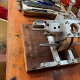
2376 forum posts 800 photos | The heads are made from c.i. and I coordinate drilled the hold down holes and left a 20 thou spigot on the head to locate in the cylinder. I've never been much inclined to make jigs and fixtures but, especially with 2 of everything, it seems necessary. For drilling the cylinder fins for the hold down studs to pass through it all needs to be located and solidly held.
The long 3/16" centre drill worked very nicely
The heads need holes drilled and milled at various angles so I made this fixture today. The aluminium square is Loctited and screwed to a 16mm steel spigot that fits in the ER25 collet block. The square is centered on the spigot and has a locating recess for the head so, in theory, I can put all the holes in the right place using the DRO in the mill, tilting the collet block in the vice as necessary. Rod Edited By Roderick Jenkins on 30/07/2022 20:42:24 |
| GrahamS | 08/08/2022 10:52:39 |
| 36 forum posts 1 photos | Good work Rod, looks spot on. I am not too far behind you with my Hoglet build , I am finishing up the connecting rods then onto assembling the crankshaft then the bottom end is complete. Like a lot of posts I see, I am not happy with the design method of a 'grab' fit of the crank webs to the shaft. I am planning using grub screws between the crank pin and webs to lock them, but cant decide on a method for the crank shafts to webs as after locking the pin there is no access. As a last resort I could just loctite them I guess, but not happy with this - Can I ask how did you do this assembly? Thanks |
| Roderick Jenkins | 09/08/2022 16:49:19 |
2376 forum posts 800 photos | Hi Graham, You are actually well ahead of me - I started withe the cylinders and am currently wrestling with the heads. I started with material I had in stock while waiting for the other stuff to be delivered. I share your concerns but am a great believer in Loctite. My Wyvern crankshaft is fabricated only with the aid of Loctite 603 and has stood the test of time. Only yesterday I was disassembling a 1/2" PGMS bar in a 1/2" reamed hole fastened with Loctite and it took a lot of heat and a lot of hammering. All the best, Rod |
| GrahamS | 17/08/2022 19:53:34 |
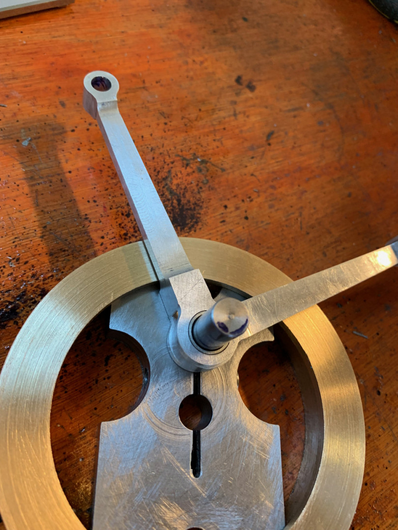
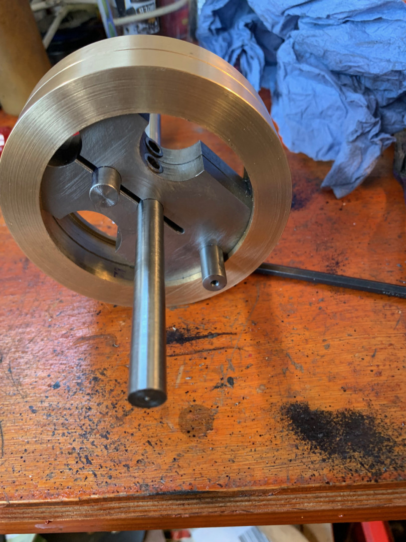
| 36 forum posts 1 photos | This is where I am up to , with the bottom end complete except for the camshaft which I have been dreading.
The length of 3/8 bar poking through both crankwebs is an alignment aid I have built in , given I had little confidence in the pinch method of holding it all together while I pinned things together. One of the crank pins was pinned first , followed by both crankshaft pieces. Then with the alignment bar in place, the other side of the crankpin was pinned. The pins are 3mm grub screws so removeable. When I am happy with it I will go back and loctite as well as pin. So far it all runs sweet so happy. Another advantage of this alignment bar is I can check everything is as it should be at any time , as in the picture the alignment bar passes through after assembly. A view of the con rods in place before crankshaft assembly.
In this one you can see I extended the split in the crankweb to try and get more grip , to no avail
Please keep posting pictures of your build, thanks! |
| Roderick Jenkins | 19/08/2022 18:41:52 |
2376 forum posts 800 photos | Nice work Graham. I guess it might be useful to know what the Hoglet looks like. Here's a sketch taken from the Model Engine Builder article. It can bee seen why the inlets are set at half the V angle. The drawings are available in MEB issues 10 and 11 and available by PDF download for a modest fee.
I generally us an ER25 collet holder in my mill but in this case headroom is rather too tight so I used my Myford collets which fit the nose on the mill spindle. Once the DRO was zeroed in on the centre of the head I could use various stub drlls to make the required holes according to the drawing
The inlet and exhaust ports were drilled in the lying down mode and the relief for the push rods were milled with a ball ended mill. Trying to mill these reliefs with an end mill in the vertical mode did not go well, as evidenced by the gouges on the build plate - that was a scrapper
Inlet and exhaust ports are modified by counter-boring at the half V angle
Probably my fault but I could not find enough information on the drawing to work out where to start the angled counter-bore to intersect the inlet and exhaust holes so had to do some sketching to get a measurement to put the cutter in the right place
In this case, my 7/16" milling cutter happens to be on a 2MT shank which was a happy accident
The inlet has a 90 degree chamfer on the transition to the through hole so I had to make a D bit cutter out of silver steel
Quite pleased with the result
The spark plug hole is 10x1mm (M fine) drilled at 30 degrees. However it needs to be counter-bored 7/8" for tube spanner access. I usually use an Arrand boring head for this sort of thing but the bottom of the counter-bore needs to be flat for the spark plug to seat. So I dug out my Dore boring and facing head which I bought on ebay. I didn't have much hope for using the magnetic stand to hold the striker arm but in fact it worked very well
I returned the heads to the lathe to cut the fins. For the first time in the 10 plus years since I have had a VFD control on the Myford I had to use back gear. 50rpm was a nice comfortable speed with plenty of torque
That all got a bit tense towards the end but they turned out OK. I hope you find this mildly diverting. Rod |
| Howard Lewis | 19/08/2022 18:58:35 |
| 7227 forum posts 21 photos | Splendid work Rod! Should be quite an item when completed. Just wish that I had your patience and skill! Howard |
| JasonB | 19/08/2022 19:01:12 |
25215 forum posts 3105 photos 1 articles | Looking good Rod, I think the 0.700" dimension is where the ctr line of the angled hole goes but it's a while since I did mine. |
| Roderick Jenkins | 25/08/2022 23:21:44 |
2376 forum posts 800 photos | The crankcase is made from 4 bits of 1/4" ally plate. Front and back machined together, drilled and reamed for the crankshaft bushes
I made a bush from 1/2" PGMS to keep the plates aligned for further work
Milling the 21 degree angles for the cylinder seats (after cutting off most of the waste on the Lidl bandsaw)
Then hacking out the profile
and finishing with a 6mm slot drill and a 6mm ball end mill
The hole for the cylinder seat was step drilled in the pillar drill to 1" then transferred to the mill to use the boring head for final sizing
Then drilling the various holes
Tapping the holes on the side plates using the GHT pillar tool
I'm trying now to get a good join at the "ridge" so the side plates were fastened at the correct spacing to a base plate and the crankcase top plate angle machined in situ. With a bit of dead reckoning and a couple of swaps from side to side I was happy with the result
Cutting the "eaves" in situ as well
It's OK
More holes to make in the crankcase front for the cam housing and cam shaft. The spacing from the crankshaft to the camshaft will be slightly altered from the drawing because I will be using 0.8M gears instead of 32DP. Rod |
| Craig Brown | 26/08/2022 05:56:44 |
| 110 forum posts 57 photos | Posted by Roderick Jenkins on 25/08/2022 23:21:44:
It's OK
Looks pretty seamless too me. If this is just OK then I look forward to a part you are very pleased with. Thanks for the pictures and details, enjoying the build. |
| GrahamS | 27/08/2022 09:37:58 |
| 36 forum posts 1 photos | Looks excellent Rod, I will find the pictures for machining the heads very useful ! Looks like you are rapidly catching me up ! Having done everything else in the bottom end , I am going to try a set up for the cam shaft next , on scrap first as I am confident there will be a few practice runs. |
| JasonB | 27/08/2022 10:00:35 |
25215 forum posts 3105 photos 1 articles | A couple of pics of machining the cam for mine if it's useful
|
| GrahamS | 28/08/2022 21:45:20 |
| 36 forum posts 1 photos | Thanks for the pics Jason, that is a help. I think I just need to man up and make a start ! My main question is about the angular relationship between the cams, and which one is which ! Referring to the Camshaft Assembly drawing ( side on view ) and the end on view with the separation angles, how do you link the two together? Assuming the cam furthest from the cam gear is the first one to be machined ( the orientation you used to machine with the long part of the camshaft in the collet ) , is the next one at 101 degrees further on or 113 or 214 ? Mu guess is the first one is at roughly 8 o clock on the drawing , the large middle one at 12 o clock and the last one at about 4 o clock? Hope that makes sense and thanks
|
| Roderick Jenkins | 29/08/2022 00:19:29 |
2376 forum posts 800 photos | My interpretation is that, since the drawing is third angle projection, the cam angle view is from the left side so the first cam is the 8 o'clock, the middle is 12 o'clock and the last is 4 o'clock. However, Jason has held his blank by the long end so the order of machining is reversed - 4 then 12 then 8. I'm still having an internal debate as to whether to make the cams as described in MEB or use CamCalc. Since the base circle has to be machined incrementally anyway I'm not sure whether the MEB method saves much time since the nose radius has to be finished by hand. I have bought issue #7 of MEB so I have been tempted to try this method. Rod |
| Roderick Jenkins | 01/09/2022 11:48:47 |
2376 forum posts 800 photos | A digression on cams. I've been slightly sceptical of the accuracy of the method that Randall Cox uses(and never really understood) to produce the cams (as shown in Jason's pictures) so I thought I would have a look at the process and compare it with the Manual Numerical Control method that is CamCalc. However, I must emphasise that the Cox method clearly works because there are many examples of running Hoglets. I drew the Cox process (I loved my Spirograph when I was a kid). The large circles are the path of the cutter as it moves around the blank in 5 degree steps with the flank radius offset of 0.4" and a lift of 0.065"
A couple of points first: For a truly Harmonic cam the transitions between the base circle and the flank circle must share a radius, as must the transition between the flank circle and the nose circle. Although not given as a parameter in the Hoglet drawings, the CAD sketch shows that the action angle of the cam (the transition from base to flank) is 135 degrees. The nose circle is drawn as a tan, tan, tan circle to the the 2 flanks and the maximum lift line. Using these parameters in CamCalc I get this:
The nose radius from CamCalc is a little larger than the Cox method shows (which is constructed by filing until it looks right). In CamCalc a sharper nose would be given by reducing the flank radius slightly. The CamCalc method always seems a little laborious (not to say tedious) - take a cut, wind the handle,move the cutter height, take a cut, wind the handle, move the cutter height, take a cut... but the Cox method is no different really. I would use a 3 degree increment for this size of cam and Cox uses 5 degrees. Conclusions: I like the Cox method, it has an elegant simplicity that does not require following a list of numbers. It is not quite as accurate as CamCalc in the nose area but for the sort of engines we make this is immaterial. For this particular engine there is a down side and that is that the cams must be machined in the vertical mode with the ensuing problems of rigidity with an interrupted flycut. With CamCalc the cam blank would be horizontal and the machining is a light cut with an end mill for each increment of rotation and no risk of interference from the boring bar on the subsequent cams. I shall be using the Cox method for my Hoglet 'cause it's good enough and a different challenge and I like that. Rod
Edited By Roderick Jenkins on 01/09/2022 11:49:46 |
| JasonB | 01/09/2022 12:05:39 |
25215 forum posts 3105 photos 1 articles | The Cox method also needs less blending of the facets than the CC as the fact they are cut to a large radius leaves a smoother finish. Rod are you not tempted to do it on the CNC these days, I think the cut time for the last cam I did was about 70seconds which is far less than CamCalc . No need for final hand finishing and you can blend whatever radii you like for the nose. You would probably have to use a tee slot or woodruff cutter to do the Hoglet one as a single part. Could even cut it in three pieces and loctite them onto the silversteel shaft, should be enough area for loctite if you did the outer cams integral with the spacers and then just the central longer one to length then they could be done with say a 6mm milling cutter. |
| Roderick Jenkins | 01/09/2022 13:04:42 |
2376 forum posts 800 photos | Posted by JasonB on 01/09/2022 12:05:39:
The Cox method also needs less blending of the facets than the CC as the fact they are cut to a large radius leaves a smoother finish. Rod are you not tempted to do it on the CNC these days... Yes. Sadly, I dont think my Sherline mill with its maximum collet size of 1/4" is rigid enough to make the cam shaft in vertical mode with a woodruff cutter hanging 1 1/2" out of the chuck. If only Fusion let us have a 4th axis I had thought about individual cams and cutting the gap between them so that they interlock at the correct orientation. But, the Cox method is new to me so it's always nice to try something novel. Cheers Rod PS: I think the Cox method produces a smoother facet because the cutter has a smaller radius than CamCalc which is a straight line cut and therefore of infinite radius Edited By Roderick Jenkins on 01/09/2022 13:07:59 |
| Howard Lewis | 01/09/2022 15:56:56 |
| 7227 forum posts 21 photos | Whichever method is used the finished product looks to a beautiful piece of machining.. Just wish that I had your knowledge and skills. Howard |


Please login to post a reply.
Magazine Locator
Want the latest issue of Model Engineer or Model Engineers' Workshop? Use our magazine locator links to find your nearest stockist!
Sign up to our Newsletter
Sign up to our newsletter and get a free digital issue.
You can unsubscribe at anytime. View our privacy policy at www.mortons.co.uk/privacy
Latest Forum Posts
- *Oct 2023: FORUM MIGRATION TIMELINE*
05/10/2023 07:57:11 - Making ER11 collet chuck
05/10/2023 07:56:24 - What did you do today? 2023
05/10/2023 07:25:01 - Orrery
05/10/2023 06:00:41 - Wera hand-tools
05/10/2023 05:47:07 - New member
05/10/2023 04:40:11 - Problems with external pot on at1 vfd
05/10/2023 00:06:32 - Drain plug
04/10/2023 23:36:17 - digi phase converter for 10 machines.....
04/10/2023 23:13:48 - Winter Storage Of Locomotives
04/10/2023 21:02:11 - More Latest Posts...
- View All Topics
Support Our Partners


Shopping Partners
Subscription Offer

Latest "For Sale" Ads
- Reeves** - Rebuilt Royal Scot by Martin Evans
by John Broughton
£300.00 - BRITANNIA 5" GAUGE James Perrier
by Jon Seabright 1
£2,500.00 - Drill Grinder - for restoration
by Nigel Graham 2
£0.00 - WARCO WM18 MILLING MACHINE
by Alex Chudley
£1,200.00 - MYFORD SUPER 7 LATHE
by Alex Chudley
£2,000.00 - More "For Sale" Ads...
Latest "Wanted" Ads
- D1-3 backplate
by Michael Horley
Price Not Specified - fixed steady for a Colchester bantam mark1 800
by George Jervis
Price Not Specified - lbsc pansy
by JACK SIDEBOTHAM
Price Not Specified - Pratt Burnerd multifit chuck key.
by Tim Riome
Price Not Specified - BANDSAW BLADE WELDER
by HUGH
Price Not Specified - More "Wanted" Ads...
Get In Touch!
Do you want to contact the Model Engineer and Model Engineers' Workshop team?
You can contact us by phone, mail or email about the magazines including becoming a contributor, submitting reader's letters or making queries about articles. You can also get in touch about this website, advertising or other general issues.
Click THIS LINK for full contact details.
For subscription issues please see THIS LINK.
Digital Back Issues


Donate

 Register
 Log-in
Model Engineer Magazine
- Percival Marshall
- M.E. History
- LittleLEC
- M.E. Clock

ME Workshop
- An Adcock
- & Shipley
- Horizontal
- Mill

Subscribe Now
- Great savings
- Delivered to your door

Pre-order your copy!
- Delivered to your doorstep!
- Free UK delivery!
All Forum Topics > Work In Progress and completed items > Rod's Hoglet