Forum sponsored by:

Reinventing Jason's Reinvented Real
| SillyOldDuffer | 24/05/2022 15:37:47 |
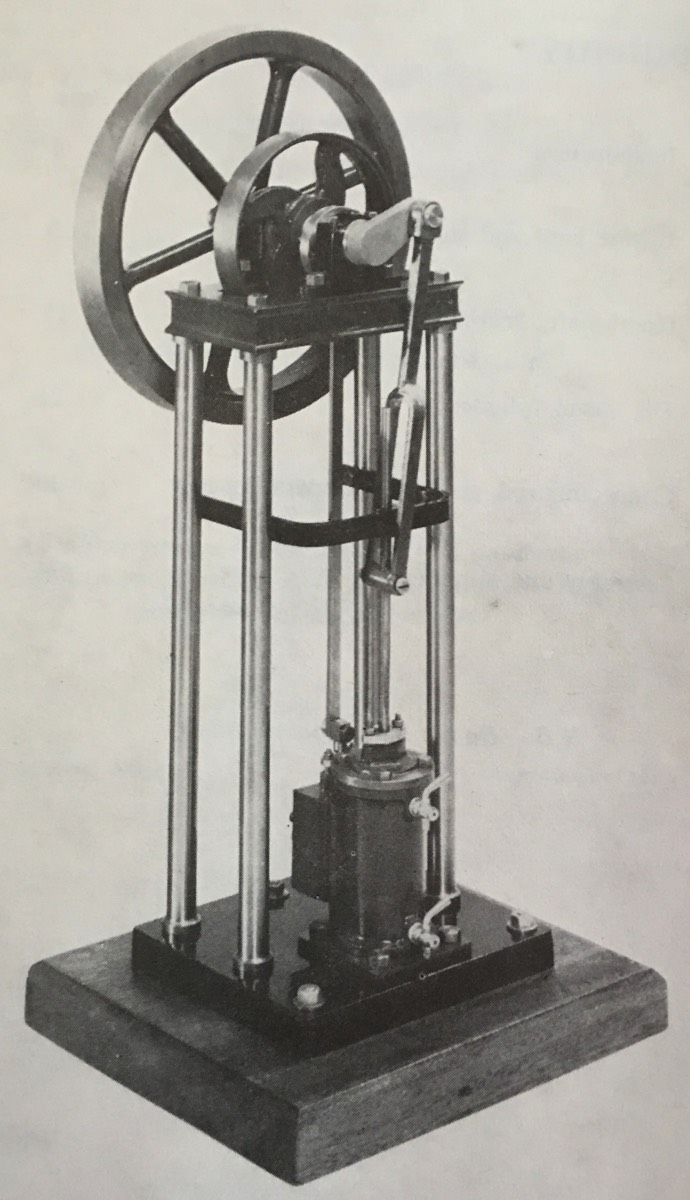
| 10668 forum posts 2415 photos | This thread is about how 3D CAD helps designers spot errors as a design develops. It's founded on JasonB's build thread, which is inspired by the Stuart Turner Real Engine, based on a full-size type.
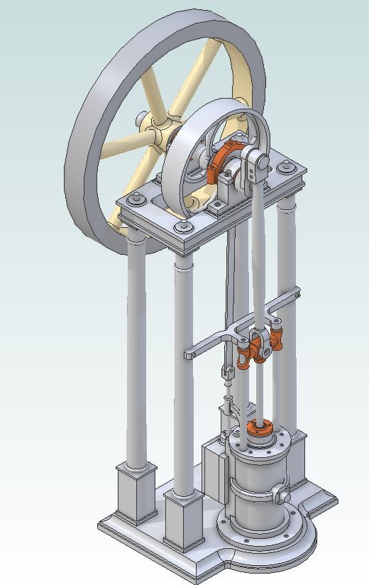
Learning Solid Edge, I was looking for an advanced Assembly exercise in which I develop an entire engine from a photograph only. The goal to create engineering drawings from an idea of the layout without the dimensions needed to build a working model. Jason often does this, and I can work from his latest . In CAD Jason's Real Engine looks like this::
And my unfinished blinged-up clone in SolidEdge:
Not bad, but CAD helps spot important errors:
A - eccentric can't connect to the slide-valve (when it's added). Easy fix A serious flaw in the cylinder:
Here, one of the 8 PCD stud-holes, circled D, is too close to the steam port. All 8 holes need to be rotated to provide clearance. I need a dimensioned Third Angle Plans to fabricate parts in my manual workshop, no castings. CAD generates the plans, and the operator adds dimensions and other annotations as necessary by clicking.
The cylinder example reveals another glitch - the dimensions highlight the chance to use standard stock sizes has been missed! Reducing the amount of unnecessary machining and swarf.is always worthwhile. Makes me appreciate Jason's efforts even more! Dave Edited By SillyOldDuffer on 24/05/2022 15:42:23 |
| JasonB | 24/05/2022 15:53:06 |
 25215 forum posts 3105 photos 1 articles | The eccentric won't be such an easy fix as when you move the cylinder further out the valve chest will move too and then you find the eccentric rod hits the entablature. Took quite a while playing about altering parts and then looking at the assembly as it updated to get something I was happy with. You will probably also need a 5 stud bottom cylinder cover fixing as your nuts will be close to the passages. Yes it's a separate part so you can bore the cylinder right through not blind as you have it |
| PatJ | 24/05/2022 16:54:37 |
 613 forum posts 817 photos | I can remember when JasonB was not a 3D modeler believer (yes it is true; I speak the truth), but he has indeed crossed over to the 3D side. I have mentioned before, but it is worth repeating, 3D modeling is worth its weight in gold as a model engine design tool. For me, designing an engine without 3D would be like trying to build an engine without a lathe. Sure, it could be done, but why not use a lathe? I am not sure about other programs, but Solidworks 2012 came with a rudimentary "Motion Study" part of the program. I was not sure about how to work the motion study part, but it has turned out to be very useful. For SW motion study, you basically drag parts onto the page, and mate them one at a time. I discovered the hard way that you can mate things such that the parts bind when rotated, but learned this only after making a complete assembly, which then mysteriously would not run in simulation. So now I drag in one part at a time, such as a crankshaft, and mate that to the bearings. Then I rotate the crankshaft using the on-screen hand, where you can move things just as if you were using your hand to rotate something. If the part will not rotate after you have assembled it, something is binding. This is a very useful tool, since you can discover which parts don't fit right, because when you add them to the assembly, and mate them, all of a sudden the engine won't rotate. Remove the offending part, and the engine rotates virtually again, and so you can figure out what is binding. Discovering alignment issues as shown above are another great example of how useful 3D modeling is. . Edited By PatJ on 24/05/2022 16:57:28 |
| JasonB | 24/05/2022 17:09:52 |
25215 forum posts 3105 photos 1 articles | Alibre will show up any clashes of static parts like trying to put a 6mm shaft into a 5mm hole and won't allow you to constrain something that can't be constrained such as two holes in two parts that have different ctr distance Talking of constraints looks like a concentric one is needed to get the cylinder sitting centrally on the half round protrusion of the base.
Dave has also slipped into the trap of designing something that will be hard to make but was easier to draw. The tight internal corners and "mitred" concave moulding shown at "B" will not be easy to machine as the cutters will leave an internal radius |
| SillyOldDuffer | 24/05/2022 19:30:49 |
| 10668 forum posts 2415 photos | A few improvements: the pillars weren't long enough to accommodate the piston stroke, so I lengthened it by eye. Jason's point about the tight corner is corrected, sort of, Added a conrod, and made a start on the guide slide, and connected the piston. Also moved the eccentric along the shaft - didn't dare look to see if it fouls the top, I think Jason is right, it will. The concentric constraint between cylinder and base isn't missing - optical illusion. the garish colours don't help! Ought to rotate and move the piston now but doesn't. Can't see why not. I'm finding Solid Edge fey about maintaining rotation lock/unlocks - seems to flip them when I'm not looking.
And I can't get the model straight on the screen! Dave Edited By SillyOldDuffer on 24/05/2022 19:31:24 Edited By SillyOldDuffer on 24/05/2022 19:32:33 |
| SillyOldDuffer | 24/05/2022 21:19:30 |
| 10668 forum posts 2415 photos | After dinner and beer, I found the duff constraint and fixed it allowing the flywheel, crank and piston do move together. Problem: the piston hits the bottom of the cylinder just before bottom dead centre, crunch:
I can turn off the cylinder to show the piston has about 4mm clearance at top dead centre:
Suggests shortening the conrod by 4mm will allow the piston to run full travel inside the cylinder without hitting the ends. Hope so because the other options are more complicated - changing the cylinder length, crank throw etc. Dave |
| Nick Wheeler | 24/05/2022 22:05:53 |
| 1227 forum posts 101 photos | Posted by SillyOldDuffer on 24/05/2022 21:19:30
 uggests shortening the conrod by 4mm will allow the piston to run full travel inside the cylinder without hitting the ends. Hope so because the other options are more complicated - changing the cylinder length, crank throw etc. uggests shortening the conrod by 4mm will allow the piston to run full travel inside the cylinder without hitting the ends. Hope so because the other options are more complicated - changing the cylinder length, crank throw etc.
That's why you design the mechanism first, and add the pretty pillars and base once you know it's all going to work. That way, all you'd need to move would be a well defined plane....
As an example here is my doodle for a small, fabricated, powered shaper that would work, but shows where the material needs to be rather than where I thought it should be(the blue top plate supporting the ram needs to be shorter in the front and longer in the back)
This was more of a mental exercise for how the mechanism works, using some guesstimated basic dimensions Edited By Nicholas Wheeler 1 on 24/05/2022 22:19:15 |
| PatJ | 24/05/2022 22:25:54 |
613 forum posts 817 photos | I select a bore and stroke, and then lay out the cylinder and passages around that in 2D CAD, to get the working geometry of the piston/rod/crosshead/connecting rod/crank pin. I then use that geometry when I start with a 3D model. Turning an exterior wall translucent is a very helpful feature, when you need to look inside of things like cylinders, and see what is happening when you rotate the crankshaft. So I guess I uses a "start inside and work out" method for engine design.
Edited By PatJ on 24/05/2022 22:26:23 |
| JasonB | 25/05/2022 07:11:39 |
25215 forum posts 3105 photos 1 articles | It's not just the piston travel that needs to be checked, the angular movement of the conrod needs to be checked to make sure it does not hit the tops of the guides in this layout so there will be some playing about with the guide length, cross head, conrod and piston rod. I would have thought SE has a "section" option, I use that a lot in alibre to check for things like this when assembling parts. As Pat says transparent parts can also be useful..
regarding getting the assembly to stand vertical on the screen again I would have thought SE has something like Alibre where there is a row of icons along teh top all the time that whan clicked give set views and isometrics, also when in the view mode rather than assembly you get the whole of teh isometric view icons which are the lower ringed group. All will stand the assembly upright and place it ctr of screen.
Alibre also has the option to toggle on or off a view cube much like you get with F360, click any face to see that elevation square on, any corner or edge to get that view. Or just click and drag.
|
| SillyOldDuffer | 25/05/2022 10:04:53 |
| 10668 forum posts 2415 photos | Posted by Nicholas Wheeler 1 on 24/05/2022 22:05:53:
Posted by SillyOldDuffer on 24/05/2022 21:19:30
uggests shortening the conrod by 4mm will allow the piston to run full travel inside the cylinder without hitting the ends. Hope so because the other options are more complicated - changing the cylinder length, crank throw etc.
That's why you design the mechanism first, and add the pretty pillars and base once you know it's all going to work. That way, all you'd need to move would be a well defined plane.... As an example here is my doodle for a small, fabricated, powered shaper that would work, but shows where the material needs to be rather than where I thought it should be(the blue top plate supporting the ram needs to be shorter in the front and longer in the back) That would be my usual approach, essential in 2D whenever parts have to fit and move together in complicated ways. But 3D CAD offers new opportunities, and Solid Edge has a feature I've not come across before: it can create new parts by building on the existing assembly. The cylinder top was done that way. In the assembly display I selected the top of the cylinder and used it as a template, with no need to remember any dimensions or alignments. Quick and natural. In this case Jason, Stuart Turner, and 19th century engineers have already done most of the hard work for me! They created the mechanism and a layout that works, and I can imitate their build-style as well. All I have to do is approximate the layout and tweak dimensions until the model 'runs'. Previously I'd have started as described by PatJ, roughed out a blocky layout like your shaper example, and not worried about fanciful curves until everything else was tickety-boo. But as it's trivial to model a Jason style base and pillars I did so. I had to change both, but not a big problem. Otherwise, most of my parts are block- unfinished: the cylinder has no steam ways, the eccentric is impossible to make, and there are no fixings yet. Although Jason's version is far more complete, mine could be brought closer to his standard by filling in lots 'mere details'. This is the latest version: I had to alter the piston rod and cylinder lengths to get it to work. Looks much the same, except the flywheel spins, turns the crank, which lifts and drops the piston inside the cylinder via the conrod without hitting the ends. The eccentric works too, though it's not connected to anything yet.
Much delay caused by finding and fixing broken relationships, likely caused by a stupid learner driving a stupid computer! Whilst I appreciate Solid Edge more and more, I'm not finding it easy to learn. Behind the scenes, what I'm doing is very like the 'Goes Wrong Show'. Making reasonable progress though, the cat hasn't been kicked yet. Dave
|
| SillyOldDuffer | 25/05/2022 21:36:59 |
| 10668 forum posts 2415 photos | Well, 3 steps forward, 2 back. The reason the model wouldn't sit straight on screen was I must have accidentally rotated the base off the top plane at some point, don't know how - some sort of 3D earthquake. Added guide rails, valve box, connected the eccentric and dropped the psychedelic colour scheme.
Another huge fight with relationship constraints today, I think because I don't understand them properly. Despite bugs the model nearly rotates properly, except the axle jumps out of the bearing blocks unless the flywheel is turned dead slow. I believe the model's parts jumping out of position is caused by setting one or more relationships incorrectly and/or by an interference.
Jason was right about the eccentric not aligning with the valve box, it's about 7mm out. For the time being I've fixed the error with a bent strap. Still lots of flaws in the engine and my CAD technique. Dave |
| PatJ | 25/05/2022 22:21:23 |
613 forum posts 817 photos | Nice 3D work ! 3D modeling is addictive. Its like opening a bag of potato chips; you really don't just eat one, and there is always one more to eat. I have talked to some who have given up physical model building completely, and they only build in the virtual world now (heaven forbid). And it can all lead into 3D printing patterns, and then castings, and so the possibilities are somewhat endless. . |
| Emgee | 25/05/2022 22:25:04 |
| 2610 forum posts 312 photos | Dave, have you tried aligning the axis of the shaft and axis of the bearing blocks ? Emgee |
| SillyOldDuffer | 26/05/2022 09:38:44 |
| 10668 forum posts 2415 photos | Posted by Emgee on 25/05/2022 22:25:04:
Dave, have you tried aligning the axis of the shaft and axis of the bearing blocks ? Emgee I'm impressed - that fixed the problem! I spent ages looking for an incorrect constraint, when it was missing entirely. A mistake! Choosing constraints calls for a level of judgement. For example, I've discovered leaving pins out of joints works well and is less likely to go wrong!
Also rotating the crank shows the conrod comes perilously close to the guide rails, but I got away with it. However, if I upgrade to a proper tapered conrod like Jason's, there's a high risk it will collide with the stanchion. I have a choice: fix it properly, or pretend a straight conrod was deliberately chosen to be easier to make... Have to go shopping now and resent it. As Pat says 3D modelling is addictive - another kind of Joint! Dave |
| JasonB | 26/05/2022 13:20:19 |
25215 forum posts 3105 photos 1 articles | Dave, not usual to have two pivot points. in the eccentric rod as the valve rod could just remain stationary as the upper joint moves sideways. Otherwise you are getting close and at this rate should be able to start making it by the weekend |
| SillyOldDuffer | 26/05/2022 18:02:08 |
| 10668 forum posts 2415 photos | Posted by JasonB on 26/05/2022 13:20:19:
Dave, not usual to have two pivot points. in the eccentric rod as the valve rod could just remain stationary as the upper joint moves sideways. Otherwise you are getting close and at this rate should be able to start making it by the weekend Thanks, I wondered about that. Blame my unofficial mentor - that part of the eccentric and it's rod aren't visible in the image I pinched off you! Today I added the belt-pulley and defined all the part materials before moving on to 'Explode Render Animate'. Animation was a little fiddly, but I can now generate a video of the engine turning. Latest version:
The purple dot is the Centre of Mass. Explode is quite fun and potentially useful when trying to work out how a pile of incautiously removed parts go back together. (Mum's kitchen clock never worked again!) Below is auto-explode, I think I could do better with the manual tool.
Identifying the materials and looking at the final dimensions shows this to be big by my standards, Would stand about 300mm tall, weigh 3.75kg, and contain 34 parts of which 26 are unique (excluding nuts and bolts). Mostly structural steel and brass, except I assumed the cylinder is cast-iron, The Centre of Mass is slightly higher than the cylinder top, about a third of the total height. Better than I expected, and the COM doesn't move much when the engine rotates! Another credit to the original designer is the excellence of the static balance: X is only out by 0.35mm and Y by -0.94mm. Likely the Dynamic balance is less satisfactory because the whirling crank and power take-off are perched on top of 4 tall unbraced pillars, but even so may not have been a problem at steam speed. My reading of the CAD model is that this engine is a good design. As to making one, I have to confess I started filing a small slot in an Aluminium tube last Sunday and still haven't finished... This would keep me out of mischief for months. Other excuses, there's ore to do. I haven't tackled the steam passages or the valve yet. Dave |
| JasonB | 26/05/2022 20:30:20 |
25215 forum posts 3105 photos 1 articles | You have come up a bit short again Dave, mine is 390mm to top of flywheel |
| SillyOldDuffer | 27/05/2022 09:19:27 |
| 10668 forum posts 2415 photos | Posted by JasonB on 26/05/2022 20:30:20:
You have come up a bit short again Dave, mine is 390mm to top of flywheel No problem, my engine is now bigger than yours!
Back in the Real world, I've started work on the cylinder and am unhappy about exhausting at the front through a belt; I can't think of a way of fabricating it with a lathe and mill.
Complicated around the back too:
A section view like one you did with Alibre would be handy:
Today's mission is finding out if Solid Edge can do the same. And then swap armchair for bench and catch up on some actual metalwork. (Tedious filing, which I can't keep straight.) Dave Edited By SillyOldDuffer on 27/05/2022 09:19:41 |
| SillyOldDuffer | 27/05/2022 15:07:31 |
| 10668 forum posts 2415 photos | Good news, producing Section Views with Solid Edge isn't too difficult, especially from a simple plane:
Shows a couple of potential build problems. The red ringed steam inlet hole is close to breaking through into the cylinder and the two vertical steam ways are dangerously close to breaking into the exhaust passage, The holes are drawn with flat ends, real ones would be made with 118 degree tipped twist drills, and the deep holes might wander too. The entry points at the rear into the belt look a tad awkward to get at:
And I don't like the square edged steam-ports either!
Best to fix it even though I suppose most builders would ignore the design and mill a semicircular port.
Another design question: how deep and wide should the semicircle be? I think the output area into the cylinder should be somewhat larger than the steam passage. In my cylinder the passage is a 3mm diameter hole, 7.1 square millimetres, so specifying the exit slot be cut with a 6mm end-mill 2mm deep gives roughly 10.5 square millimetres, an aperture that shouldn't throttle the engine. Nor should the exhaust belt, which is twice 15 sq mm into a 5mm diameter exit (19.6 sq mm) The bends and narrowness of the cylinders steam ways might be improved. Increasing the diameter of the steam passages through the cylinder would be good because a pipe's steam capacity follows a square law. In this engines a 4mm hole rather than 3mm almost doubles the amount of heat available for conversion to mechanical work by the piston.
Dave |
| JasonB | 27/05/2022 16:06:07 |
25215 forum posts 3105 photos 1 articles | Dave don't forget to take into account the fact that part of your semi-circular notch could get covered by the usual spigot on the cylinder covers so it may need to be deeper or you can notch the cover spigot. The Stuart casting has the passages formed by rectangular section cores and area is 22.8mm2 On cylinders that have the passages drilled it is not uncommon to use more than one hole, I'll not make you draw this many but they start from a different position around the diameter but all end in a straight line so 3 different angles x 4 sets of 3 holes. Also no issues with the cylinder cover stud in the middle on this engine.
|


Please login to post a reply.
Magazine Locator
Want the latest issue of Model Engineer or Model Engineers' Workshop? Use our magazine locator links to find your nearest stockist!
Sign up to our Newsletter
Sign up to our newsletter and get a free digital issue.
You can unsubscribe at anytime. View our privacy policy at www.mortons.co.uk/privacy
Latest Forum Posts
- *Oct 2023: FORUM MIGRATION TIMELINE*
05/10/2023 07:57:11 - Making ER11 collet chuck
05/10/2023 07:56:24 - What did you do today? 2023
05/10/2023 07:25:01 - Orrery
05/10/2023 06:00:41 - Wera hand-tools
05/10/2023 05:47:07 - New member
05/10/2023 04:40:11 - Problems with external pot on at1 vfd
05/10/2023 00:06:32 - Drain plug
04/10/2023 23:36:17 - digi phase converter for 10 machines.....
04/10/2023 23:13:48 - Winter Storage Of Locomotives
04/10/2023 21:02:11 - More Latest Posts...
- View All Topics
Support Our Partners


Shopping Partners
Subscription Offer

Latest "For Sale" Ads
- Reeves** - Rebuilt Royal Scot by Martin Evans
by John Broughton
£300.00 - BRITANNIA 5" GAUGE James Perrier
by Jon Seabright 1
£2,500.00 - Drill Grinder - for restoration
by Nigel Graham 2
£0.00 - WARCO WM18 MILLING MACHINE
by Alex Chudley
£1,200.00 - MYFORD SUPER 7 LATHE
by Alex Chudley
£2,000.00 - More "For Sale" Ads...
Latest "Wanted" Ads
- D1-3 backplate
by Michael Horley
Price Not Specified - fixed steady for a Colchester bantam mark1 800
by George Jervis
Price Not Specified - lbsc pansy
by JACK SIDEBOTHAM
Price Not Specified - Pratt Burnerd multifit chuck key.
by Tim Riome
Price Not Specified - BANDSAW BLADE WELDER
by HUGH
Price Not Specified - More "Wanted" Ads...
Get In Touch!
Do you want to contact the Model Engineer and Model Engineers' Workshop team?
You can contact us by phone, mail or email about the magazines including becoming a contributor, submitting reader's letters or making queries about articles. You can also get in touch about this website, advertising or other general issues.
Click THIS LINK for full contact details.
For subscription issues please see THIS LINK.
Digital Back Issues


Donate

 Register
 Log-in
Model Engineer Magazine
- Percival Marshall
- M.E. History
- LittleLEC
- M.E. Clock

ME Workshop
- An Adcock
- & Shipley
- Horizontal
- Mill

Subscribe Now
- Great savings
- Delivered to your door

Pre-order your copy!
- Delivered to your doorstep!
- Free UK delivery!
All Forum Topics > CAD - Technical drawing & design > Reinventing Jason's Reinvented Real