Forum sponsored by:

Reinventing The Real
A revised design for the Stuart Real
| JasonB | 21/05/2022 19:11:00 |
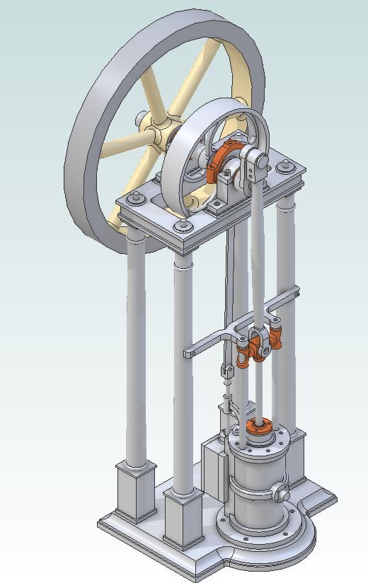
 25215 forum posts 3105 photos 1 articles | While making the Stuart Victoria last year I started to feel like I would also like to make the Real to go with it. So I bought Andrew Smith's book (cheapest source of drawings) on building the Real and started to look a pictures of them on the net, the more I looked the more I saw that I did not like and that included what Stuarts are asking for the kit. So over a few winter evenings I developed a different version that has gone by the working tile "Unreal" which addresses some of these issues and also more closely follows the etching from Andrew's book that was his inspiration. |
| PatJ | 21/05/2022 19:28:48 |
 613 forum posts 817 photos | That engine looks really nice with that center pully ? with the curved spokes. Gives the engine a very refined look, as does the base. I don't think I have ever seen an arrangement like that. And nice 3D work !! . |
| Nigel Graham 2 | 21/05/2022 21:51:37 |
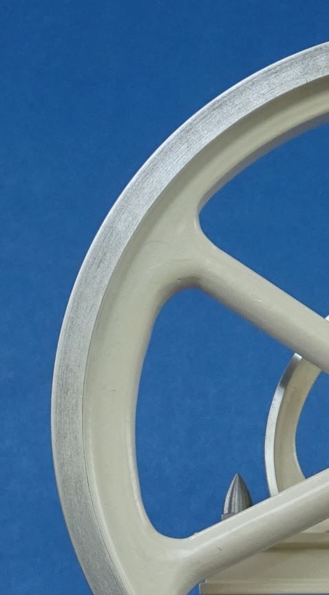
| 3293 forum posts 112 photos | A very elegant machine! It is an unusual layout - a true vertical. (The more common ones with the crankshaft at the bottom, marine-engine style, as more properly of "inverted-vertical" layout.) As finishing touches the pulley (not flywheel) would have been very slightly crowned - though that is probably barely noticeable at that scale - and it may be worth examining your source engraving to see if it had square or hexagonal nuts, especially in the larger diameters. Curved spokes were common practice on cast-iron pulleys etc, not for looks but to absorb the contraction stresses in cooling. |
| blowlamp | 21/05/2022 21:58:21 |
 1885 forum posts 111 photos | Jason. Did you draw that in TurboCAD? |
| JasonB | 22/05/2022 07:32:33 |
25215 forum posts 3105 photos 1 articles | I don't think I would have got passed the design stage let alone making it if I had used Turdbocad! Yes the pully has some crown to keep the belt tracking true and Andrew's engraving has hex fixings which I also used and although metric I did not use run of the mill mass produced ISO nuts they are all smaller hex, taller and only chamfered one side to more closely resemble earlier nuts. |
| blowlamp | 22/05/2022 14:18:02 |
1885 forum posts 111 photos | Posted by JasonB on 22/05/2022 07:32:33:
I don't think I would have got passed the design stage let alone making it if I had used Turdbocad! Yes the pully has some crown to keep the belt tracking true and Andrew's engraving has hex fixings which I also used and although metric I did not use run of the mill mass produced ISO nuts they are all smaller hex, taller and only chamfered one side to more closely resemble earlier nuts.
It's looking good. Nice attention to detail.
Martin. |
| SillyOldDuffer | 22/05/2022 15:10:11 |
| 10668 forum posts 2415 photos | I like the look of it, but wonder how practical the configuration would be in full size? Compared with a horizontal engine, the centre of gravity is high. And not only do the four spindly pillars carry a heavy flywheel and loaded belt pulley but the crank waggles from side to side, alternating the load. I'd expect the configuration to vibrate and limit the power take-off. Saves lots of floor space, but could that be better done by inverting the engine, cylinder at the top, and the heavy moving bits underneath? Can Jason's CAD tool can tell him where the centre of gravity is on this fine looking engine and how much it moves about as the engine turns? Bet it can!
Dave |
| JasonB | 22/05/2022 15:30:22 |
25215 forum posts 3105 photos 1 articles | You'll just have to wait for the video at the end and watch it slowly and smoothly ticking over at 35rpm, even when I wind the wick up it sits nice and solid Many of these engine actually only had two columns with the other end of the crankshaft running in a bearing block supported by the wall of the workshop or engine room. Also a lot easier to assemble an engine with the heavy cylinder at the bottom when all you had was block and tackle and it gives a short belt run to any overhead line shafting. |
| derek hall 1 | 22/05/2022 15:31:34 |
| 322 forum posts | I built the "Real" from Stuart Turners castings and to the design by Andrew Smith around 40 years ago. It was my first engine built with castings and I think the whole lot cost £20. I recently checked the prices for castings for this engine and thankfully was sitting down at the time. All apart from the cylinder and flywheel can be made from the solid. Agree that Jason's version is aesthetically much better looking Regards Derek |
| SillyOldDuffer | 22/05/2022 20:05:10 |
| 10668 forum posts 2415 photos | Don't like to complain, but Jason's engine is an obvious copy of my Cotton Reel!
Knew I should have applied for a patent...
|
| JasonB | 22/05/2022 20:14:40 |
25215 forum posts 3105 photos 1 articles | Well I suppose it's worth 3/10 for a half hearted effort, you have left all the tricky bits off.
|
| duncan webster | 22/05/2022 20:53:17 |
| 5307 forum posts 83 photos | Cylinder on the floor crankshaft up in the air was quite common, the next step up from beam engines. There is a twin cylinder one in Bolton steam museum (nmes.org). For fellow pedants, cylinder up in the air and crank on the floor is correctly called an inverted vertical, but I suspect this has gone by the wayside. Edited By duncan webster on 22/05/2022 20:56:48 |
| JasonB | 23/05/2022 08:17:59 |
25215 forum posts 3105 photos 1 articles | And that is why Andrew Smith gave the model this name because it is a "real" or true vertical and one with the cylinder at the top is an inverted |
| SillyOldDuffer | 23/05/2022 09:02:09 |
| 10668 forum posts 2415 photos | Posted by JasonB on 22/05/2022 20:14:40:
Well I suppose it's worth 3/10 for a half hearted effort, you have left all the tricky bits off.
I get into trouble when I tackle the tricky bits! Avoided unless they can be fixed with paint and putty. The rear view transparency confirms an interesting detail: the exhaust is carried around the cylinder to the boss-thingy on the front, which would keep the cylinder hot. As the hollow band is more complicated to make than a steam jacket, I wonder if the idea was to concentrate heat at the cool point in the middle where the piston spends most of its time. I often focus on the quaint look of early engines without noticing the design is technically clever too. How would a hollow band around a cylinder be cast? Dave
|
| JasonB | 23/05/2022 16:19:19 |
25215 forum posts 3105 photos 1 articles | I don't think the wrap around exhaust would have done a great deal in teh way of cylinder heating a sthe area in contact with teh cylinder wall is quite small, mor ejust a way of getting the exhaust connection to where it was wanted. As can be seen on this full size engine the heating would be minimal
As for how the part would have been cast that would have been done with an extra cor. As well as the main core forming the rough bore and the two dog legged ones for the inlets the stubby one for the exhaust port would have been extended around the cylinder and supported at the other side by a spigot which would have made the boss hollow and have been located in a suitable core print on the pattern.
To convert the Stuart side exhaust to the front exhaust needs a cunning plan |
| JasonB | 23/05/2022 19:02:59 |
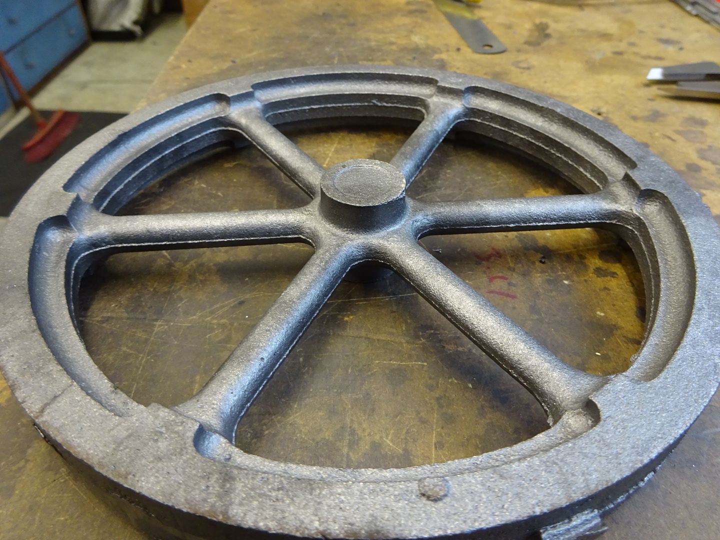
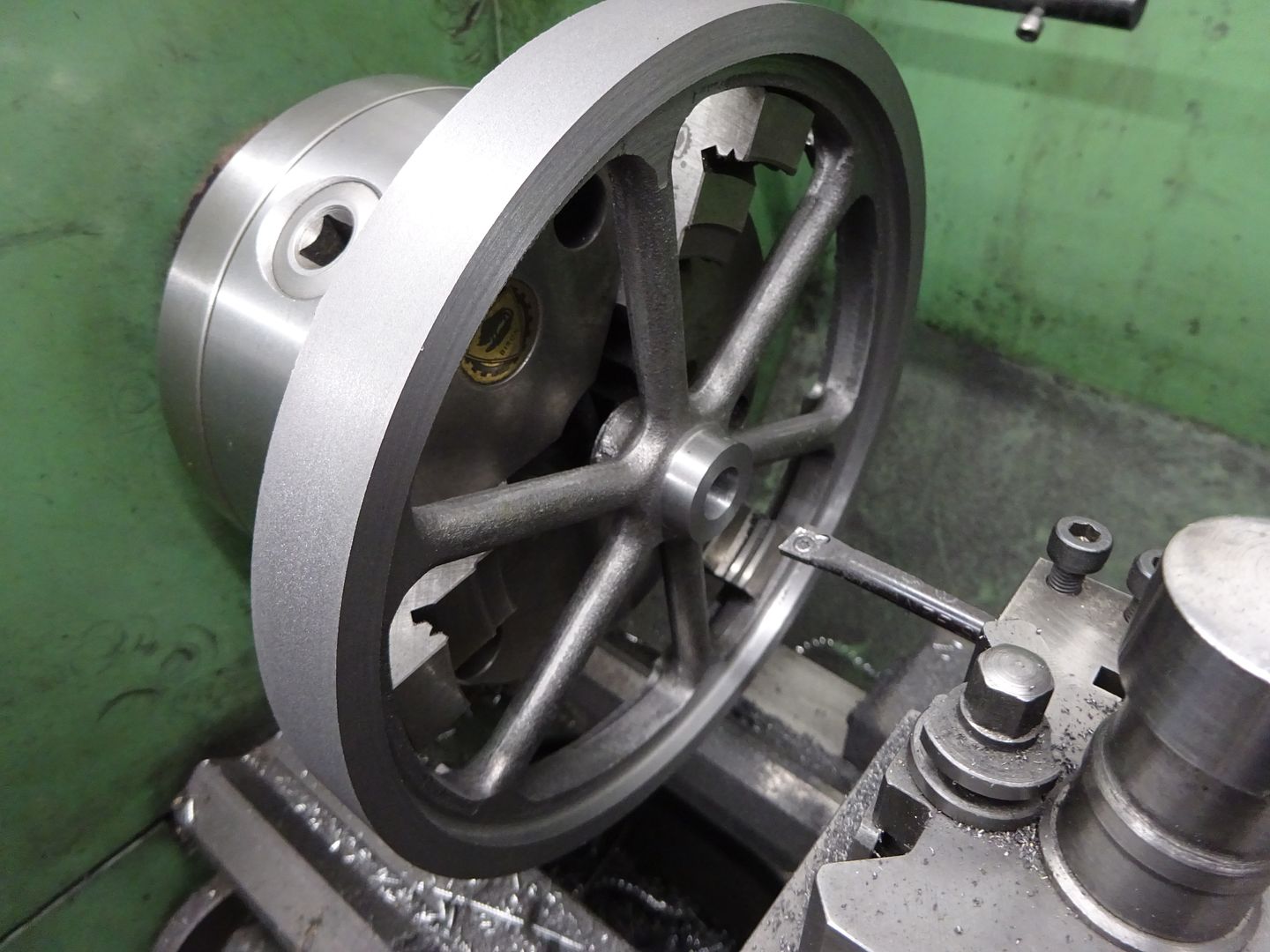
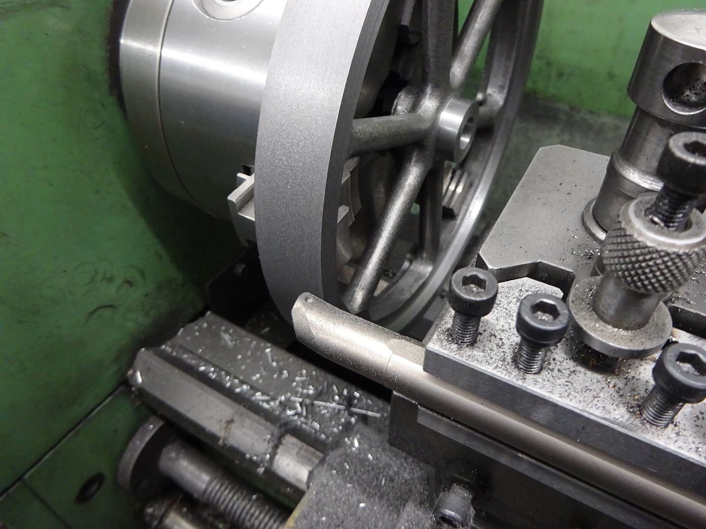
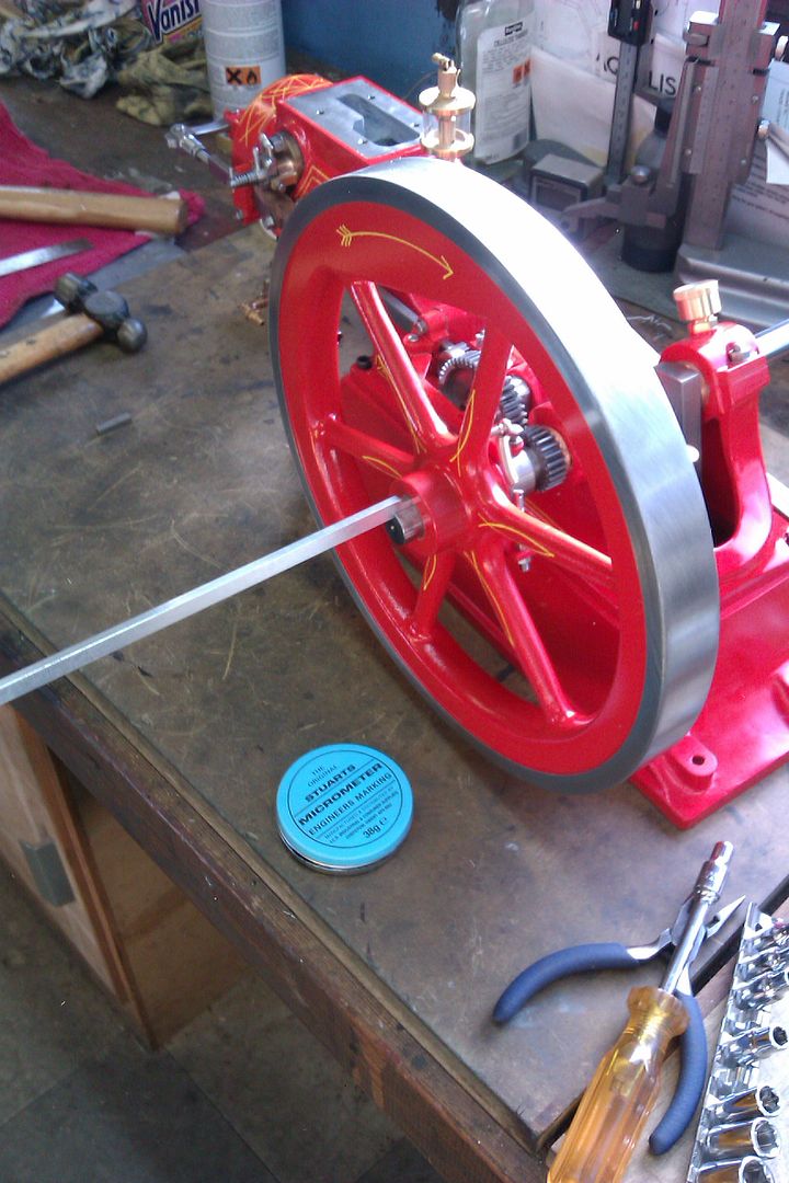
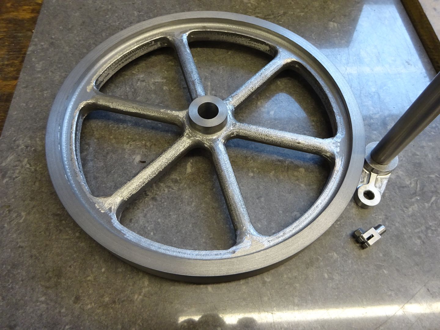
25215 forum posts 3105 photos 1 articles | I decided to make a start with the flywheel while I was waiting for a delivery of materials that would have allowed my to start with the more logical base. You seem to read a lot that the current Stuart castings are not what they used to be but I have to say that both the flywheel and cylinder castings were very good - No holes, no hard spots, mould halves lined up with no step and very little flash. The only real downside is that Stuarts seem to only supply castings from the pattern used for the twin Victoria which have the ugly bosses cast in where two flywheels are bolted together.
|
| Weary | 25/05/2022 08:50:57 |
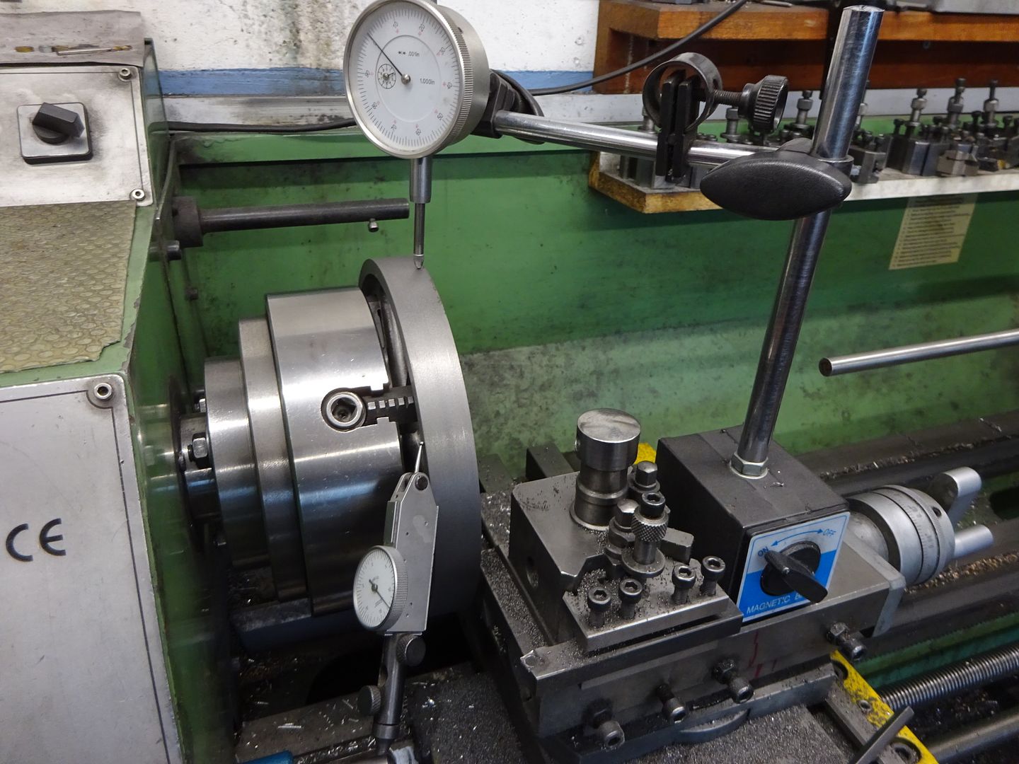
| 421 forum posts 1 photos | Jason, Very nice work! But, can you perhaps give a little more detail as to how you "used a broach to cut a tapered keyway" sometime please? Was it a home-made or commercial broach, and how did you achieve the required taper? Thanks & regards, Phil Edited By Weary on 25/05/2022 08:53:26 |
| JasonB | 25/05/2022 20:13:01 |
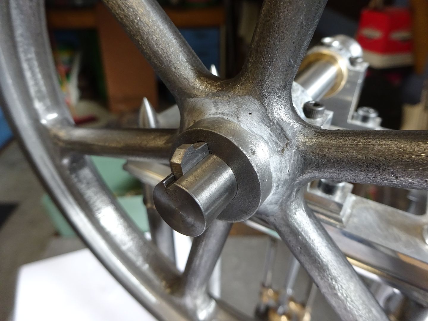
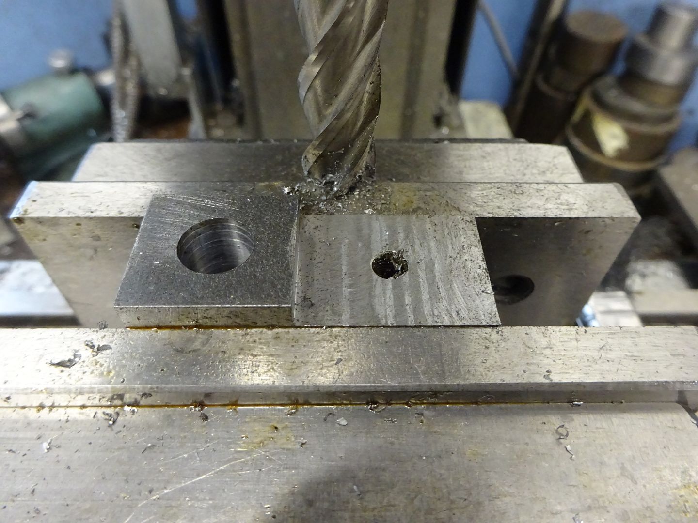
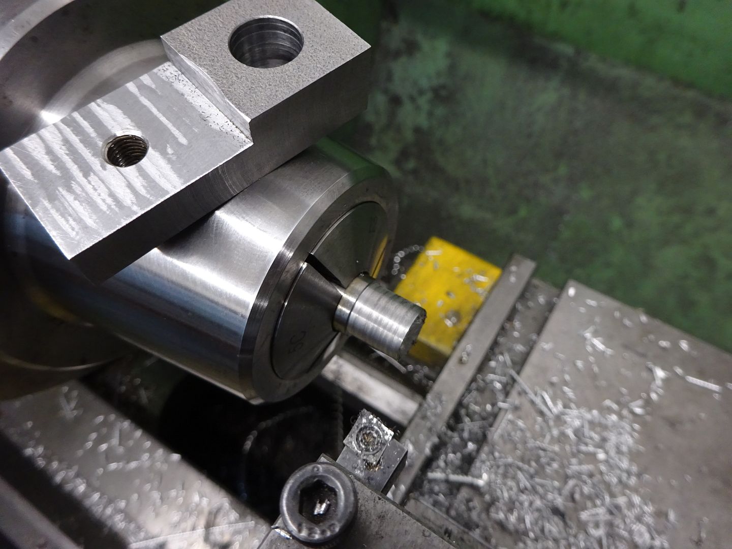
25215 forum posts 3105 photos 1 articles | It was a commercial broach but I made my own bush for it with the required taper. These are quite simple to make - just a top hat shape to fit the bore and long enough to support the broach for at least the full depth of the hole. After turning the bush is held in the mill vice at the required angle 1:100 for metric and 1:96 for imperial which is about 1.75degrees and a suitable slot cut into the bush. I've built up quite a few over time of different diameters an plain or tapered The one laying down on it's own is the one I made for this job.
The key I either cut from gauge plate or rectangular section key steel if I have it, again setting to the angle and milling the face that will touch the flywheel. They are then blued and fitted using a fine but sharp file, I find if the stock is left long it gives you a bit more to get hold of when you need to remove the key to see where metal needs to be removed.
|
| JasonB | 26/05/2022 19:22:03 |
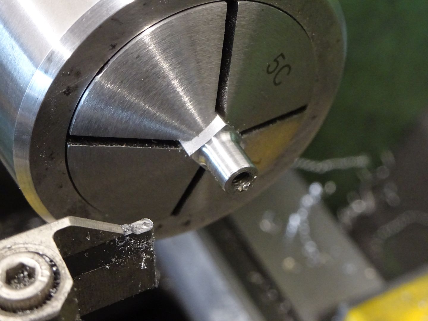
25215 forum posts 3105 photos 1 articles | As I had cut off a bit of 12mm PGMS to use as a plug gauge for the flywheel hole I thought I may as well work on the crankshaft next. |
| JasonB | 28/05/2022 17:03:59 |
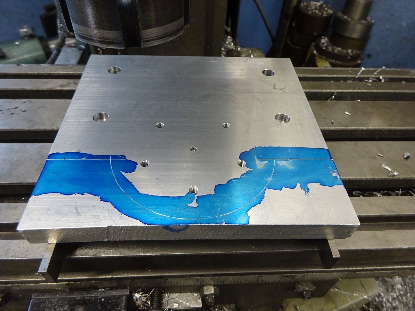
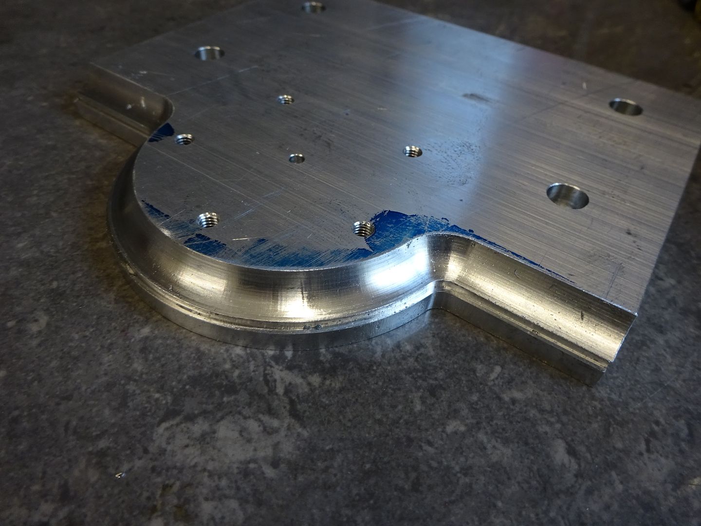
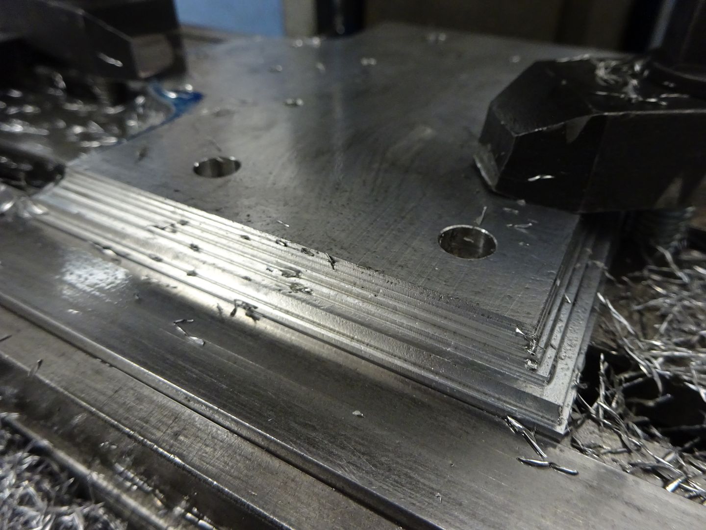
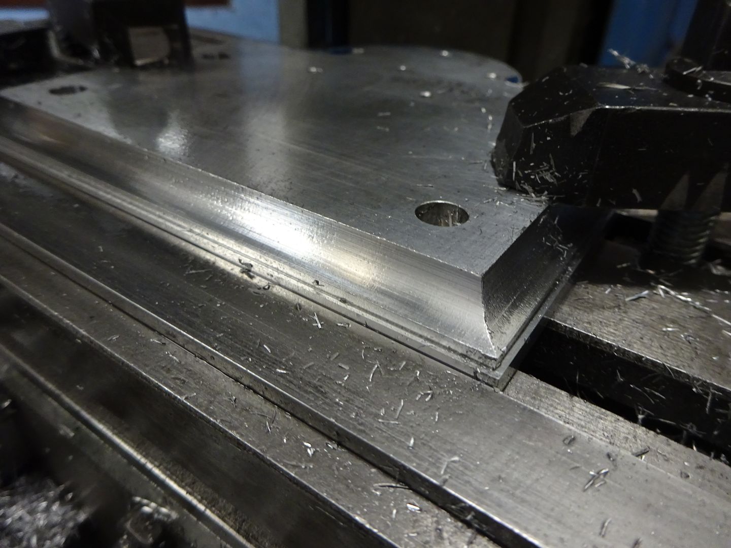
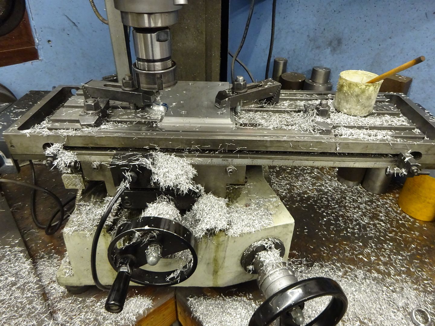
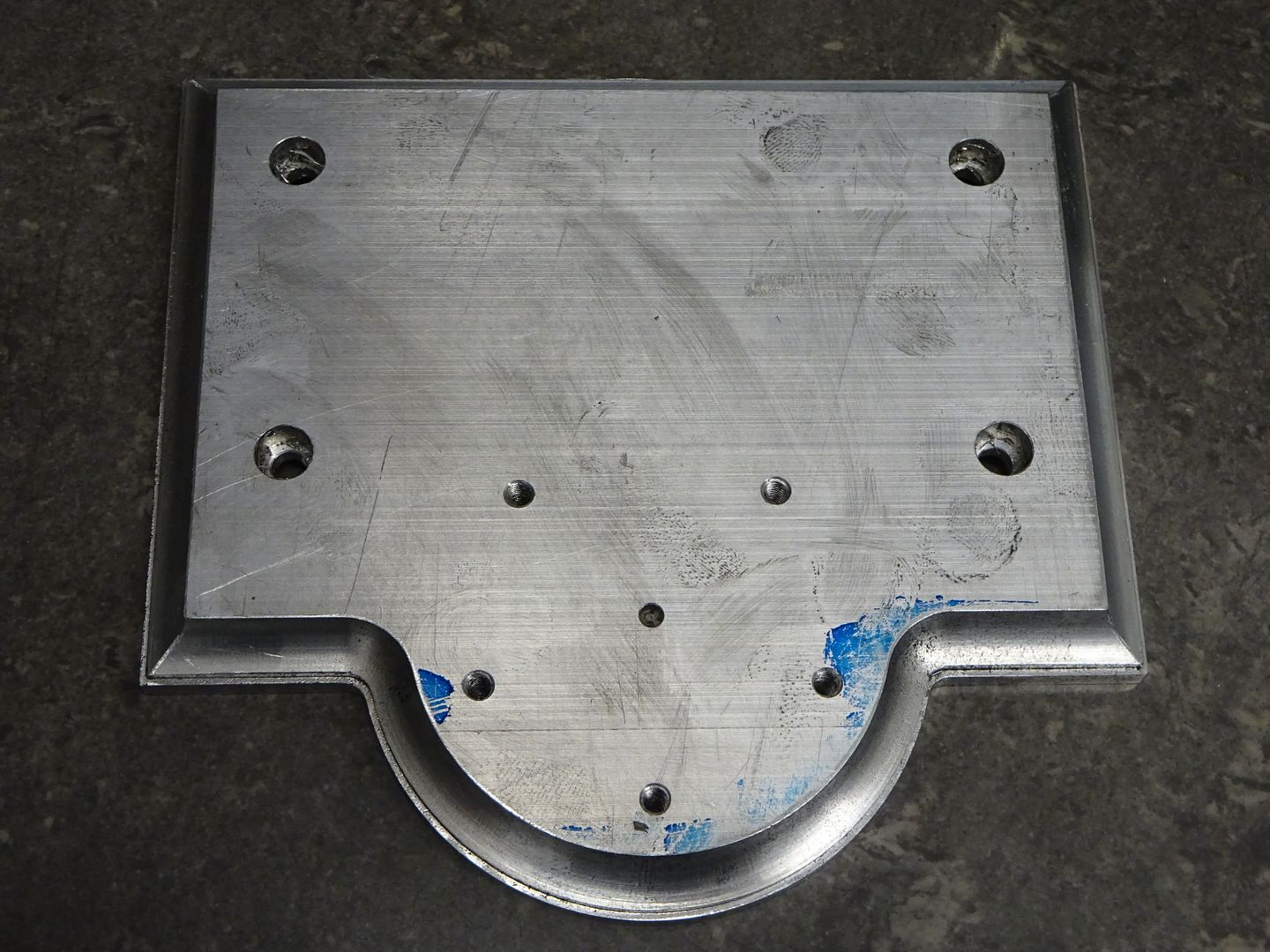
25215 forum posts 3105 photos 1 articles | With the arrival of some additional material the build can now follow a more logical direction starting with the base. Edited By JasonB on 28/05/2022 17:05:50 |


![20220525_164841[1].jpg](/sites/7/images/member_albums/44290/908375.jpg "20220525_164841[1].jpg")


Please login to post a reply.
Magazine Locator
Want the latest issue of Model Engineer or Model Engineers' Workshop? Use our magazine locator links to find your nearest stockist!
Sign up to our Newsletter
Sign up to our newsletter and get a free digital issue.
You can unsubscribe at anytime. View our privacy policy at www.mortons.co.uk/privacy
Latest Forum Posts
- *Oct 2023: FORUM MIGRATION TIMELINE*
05/10/2023 07:57:11 - Making ER11 collet chuck
05/10/2023 07:56:24 - What did you do today? 2023
05/10/2023 07:25:01 - Orrery
05/10/2023 06:00:41 - Wera hand-tools
05/10/2023 05:47:07 - New member
05/10/2023 04:40:11 - Problems with external pot on at1 vfd
05/10/2023 00:06:32 - Drain plug
04/10/2023 23:36:17 - digi phase converter for 10 machines.....
04/10/2023 23:13:48 - Winter Storage Of Locomotives
04/10/2023 21:02:11 - More Latest Posts...
- View All Topics
Support Our Partners


Shopping Partners
Subscription Offer

Latest "For Sale" Ads
- Reeves** - Rebuilt Royal Scot by Martin Evans
by John Broughton
£300.00 - BRITANNIA 5" GAUGE James Perrier
by Jon Seabright 1
£2,500.00 - Drill Grinder - for restoration
by Nigel Graham 2
£0.00 - WARCO WM18 MILLING MACHINE
by Alex Chudley
£1,200.00 - MYFORD SUPER 7 LATHE
by Alex Chudley
£2,000.00 - More "For Sale" Ads...
Latest "Wanted" Ads
- D1-3 backplate
by Michael Horley
Price Not Specified - fixed steady for a Colchester bantam mark1 800
by George Jervis
Price Not Specified - lbsc pansy
by JACK SIDEBOTHAM
Price Not Specified - Pratt Burnerd multifit chuck key.
by Tim Riome
Price Not Specified - BANDSAW BLADE WELDER
by HUGH
Price Not Specified - More "Wanted" Ads...
Get In Touch!
Do you want to contact the Model Engineer and Model Engineers' Workshop team?
You can contact us by phone, mail or email about the magazines including becoming a contributor, submitting reader's letters or making queries about articles. You can also get in touch about this website, advertising or other general issues.
Click THIS LINK for full contact details.
For subscription issues please see THIS LINK.
Digital Back Issues


Donate

 Register
 Log-in
Model Engineer Magazine
- Percival Marshall
- M.E. History
- LittleLEC
- M.E. Clock

ME Workshop
- An Adcock
- & Shipley
- Horizontal
- Mill

Subscribe Now
- Great savings
- Delivered to your door

Pre-order your copy!
- Delivered to your doorstep!
- Free UK delivery!
All Forum Topics > Stationary engines > Reinventing The Real