Forum sponsored by:

A puzzle and small disaster
Flywheel jamming on mandrel.
| James Hall 3 | 05/02/2022 00:22:29 |
| 92 forum posts 12 photos | Machining my first model from castings, a Stuart H10. |
| Emgee | 05/02/2022 00:38:48 |
| 2610 forum posts 312 photos | James Is the mandrel absolutely parallel or could it be very slightly tapered so the flywheel would be a press fit ? Emgee |
| Jeff Dayman | 05/02/2022 03:36:47 |
| 2356 forum posts 47 photos | Was the flywheel warm or hot when you placed it on the mandrel? If it was, the contraction on cooling can makes fits very tight. To check this theory with your flywheel you might try heating it around the hub with a torch, and see it will move off the mandrel. If all else fails you could machine the mandrel out of the flywheel, making the bore a bit larger and maybe fit a bushing to make up the lost material. This might avoid buying a costly new flywheel. Cast iron bores are tricky - you have to sneak up on the final size, the dust / surface texture can make the bore seem a perfect fit - but after a few assys it gets loose, or sometimes jams up. A light lapping or honing before testing fit, and plenty of solvent cleaning with lint free cloths is usually needed for final fitting in bores in iron. Another way to do flywheel mounting (in general) is to use a tapered bushing to secure the flywheel to a round shaft. In this case the flywheel bore is made with a low taper say 3 to 5 degrees and an exact mating angle is cut on the shaft bushing. the bushing can be split to have a tight grip on the shaft AND flywheel when pressed up. The taper , if made carefully, will reduce the risk of a wobbly flywheel too. Just food for thought. Good luck. |
| JasonB | 05/02/2022 07:10:37 |
 25215 forum posts 3105 photos 1 articles | What tool did you use to cut the mandrel? if an insert then a fillet is left on the internal corner and that can go tight if the hole has not been deburred enough to clear it. If a poorly honed or ground HSS bit that has a slightly convex edge rubbing on the arbor diameter then that can have the same effect by leaving a slight taper at the end. If the flywheel slipped while machining the rim that may also have caused the surface to pick up and gall. Personally I'm not a fan of mounting flywheels on arbors as the rim is not well supported and chatter is likely. |
| Clive Foster | 05/02/2022 09:18:10 |
| 3630 forum posts 128 photos | I'm with Jason on not being a fan of mounting flywheels or any other relatively large diameter component on a mandrel. Not only do you risk chatter but the constant tiny vibrations produced when machining can work the thing on until its really tight making it hard to remove without risk of breaking. Although cast iron has high damping its inherently granular so the cutting forces aren't smooth. If you have something that machines nicely with a continuous chip the steady force tends to screw the component on tighter. For parallel mandrels there seems to be a fine balance between tight enough to hold yet not so tight that it can work on hard. There is a reason why the professionals make them with a very fine taper. A few cycles of gentle warming and cooling over a few cycles can release such stuck components. Best if you can arrange something to apply a little push or pull force in the right direction. Don't get rush-headed. Even if it takes as long to get the bits unstuck as it did to get them jammed in the first place you are still ahead. I prefer to use a spindle collet and faceplate set-up for such things. Nice sliding, shake free, fit mandrel in the spindle collet to align the part. Strap it to the faceplate to hold it for machining. Aligning things on face plates is well off the bottom of my "liked jobs" list. Most especially if I have more than one the same. But, having spent far too many £ over far too many years, I have the gear. Assuming a morse taper in the spindle a blank end arbor turned to size or sleeved up as appropriate is as effective as a mandrel and collet. Considerably more wallet friendly than my full sets of imperial (by 1/64 ths) and metric (by 0.5 mm) 5C collets too. A blank arbor or two of appropriate sizes immediately to hand for modification into semi-sacrificial tooling is an essential part of any normally impecunious Model Engineer or Home Workshop persons toolkit. Building up to size with weld or sticking bits on when its gotten too small is perfectly acceptable! Clive |
| HOWARDT | 05/02/2022 09:19:26 |
| 1081 forum posts 39 photos | When applying any force on a cast iron, or any material really, support the area adjacent to were the force is being applied through. The worst you will do then is cause a bruise onto the surface. The further you support the part from where the force is applied the greater the deformation (bending) and therefore the chance of breaking. |
| Andrew Johnston | 05/02/2022 09:31:43 |
 7061 forum posts 719 photos | Posted by JasonB on 05/02/2022 07:10:37: ...not a fan of mounting flywheels on arbors... Plus one, did it once, never again. More chatter than an Islington luvvie. When I machine a flywheel I set it up on a faceplate so I can machine one side of the rim and boss, the bore and the rim at one setting. That only leaves one side to get the rim and boss to width. The flywheel doesn't need to run true to do that, which simplifies mounting on the faceplate. Andrew |
| Bazyle | 05/02/2022 09:40:26 |
 6956 forum posts 229 photos | On a faceplate do you pack it off the surface at the spokes or rim? or accept a small groove in the plate as you clear the edge? |
| not done it yet | 05/02/2022 09:42:50 |
| 7517 forum posts 20 photos | Press, not drift, would be far more gentle - with the support where it was required. Any hammering results in high impulse forces. Using a soft mallet, rather than a steel hammer, should be the automatic first choice of ‘weapon’ (preferably with a soft drift as well) if you must resort to uncontrolled force. Most likely a temperature difference, if you finished the shaft machining with fine emery, to avoid any turning irregularities. How is the taper on your lathe? Even a tiny amount may mean the shaft had to come out f the same side as it was installed. Heat or cold treatment may help in these situations (particularly steel in aluminium) due to differences in the coefficients of expansion of the materials. Probably better to machine away most of that arbor, rather than risk the casting (and any time/effort in prior machining), if the problem ever arises again. You can make another mandrel easier and cheaper than another flywheel.🙂 |
| Andrew Johnston | 05/02/2022 10:05:39 |
7061 forum posts 719 photos | Posted by Bazyle on 05/02/2022 09:40:26:
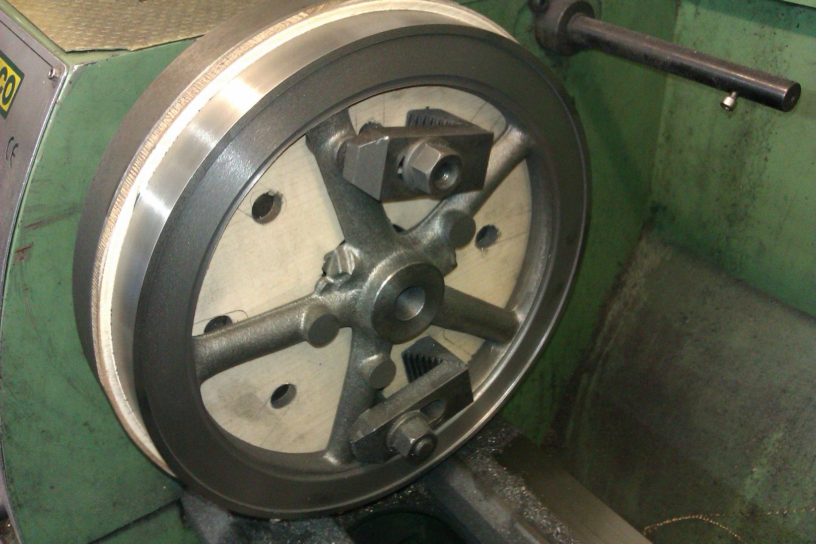
On a faceplate do you pack it off the surface at the spokes or rim? Rim; one can see the aluminium blocks, bolted to the faceplate, in this picture:
Note the four steel spigots bolted to the faceplate. These provide the drive to the flywheel, and radial location. The clamps on the spokes do not need to be more than nipped up. They are there to stop the flywheel falling off the faceplate. Andrew Edited By Andrew Johnston on 05/02/2022 10:09:14 |
| JasonB | 05/02/2022 10:17:03 |
25215 forum posts 3105 photos 1 articles | On the odd occasion that I have to do it on a faceplate I either cut a disc of 6mm MDF (I have plenty of offcuts) and the tool can run into that. Though as you tend to do the OD as the first op you can stop just short of the faceplate and the 1mm or so left can be machined off when the backside is faced.
If the flywheel has spindly spokes then I'll pack off those so they don't get distorted by the clamps, if it's a hefty flywheel then I'll clamp across the spokes. Provided the flywheel fits I'm more likely to hold in the 4-jaw with the jaws bearing on the inside edge of the rim to get that running true then turn OD, face rim & hub and bore. Always leaving the boring until last as if something is going to move then it will be while machining the rim which will then throw the bore off.. If it's a good casting then I may even use the 3-jaw
Edited By JasonB on 05/02/2022 10:19:12 |
| Ramon Wilson | 05/02/2022 10:40:20 |
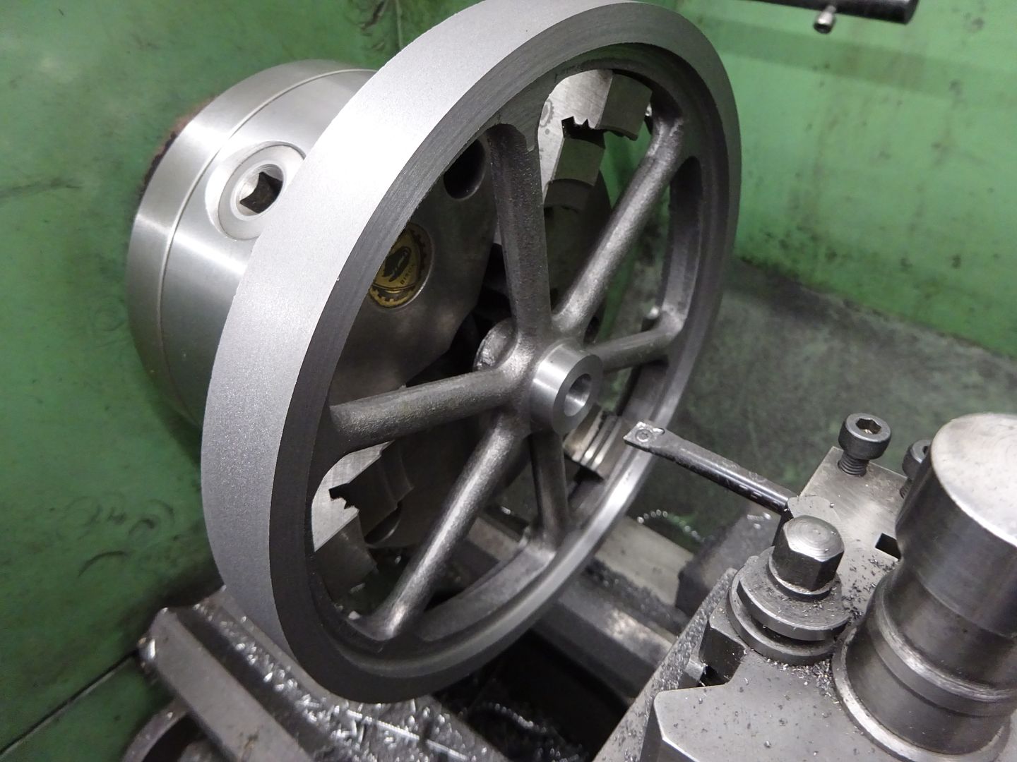
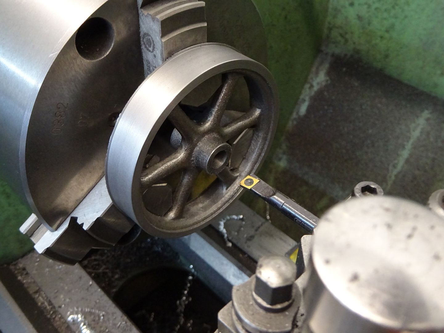
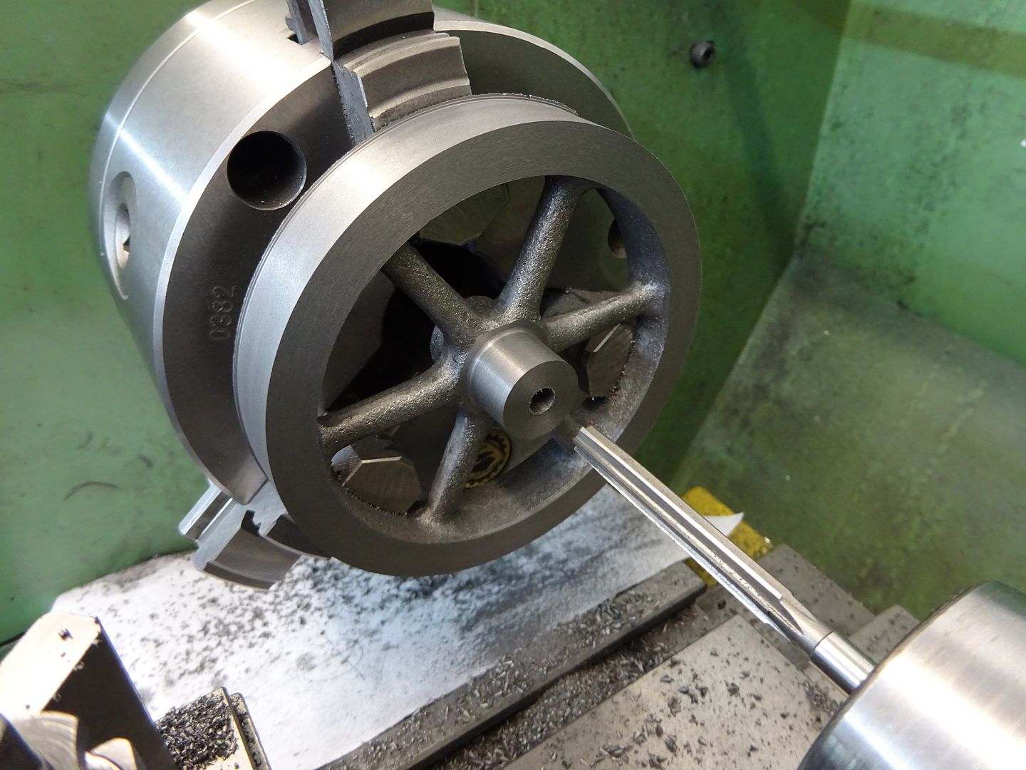
 1655 forum posts 617 photos | All the info and advice given above is sound for the flywheels shown and without question but I feel you are over looking one thing - it's a Stuart 10 flywheel that the OP is concerned with. What's that - 31/2" diameter at most? The usual Myford faceplate's slots probably don't go in far enough and besides the clamping would need to be a small affair too. There is nothing wrong with using a mandrel for such a size and providing the speed is kept well down chattering should not be an issue with a sharp tool and light cuts. I certainly wouldn't be using carbide on this though unless there were hard spots. The mandrel should be an easy fit to the bore - hand push on and off, free to move but without shake and the part retained by a sound washer and bolt. A slip of copy paper between mandrel face and washer face and the part will enhance grip. Cast is very unlikely to gall on a steel mandrel - I would think the small taper as intimated by Jason was the likely culprit. This is a fabricated wheel about 5" diameter being faced and turned on the OD off the bore. Note the HSS tooling. A firm mounting and slow rotational speed is the key to preventing chatter.
Hope that helps some more - good luck with your 10H
Tug
|
| ega | 05/02/2022 11:14:38 |
| 2805 forum posts 219 photos | I think (as, perhaps, implied above) that the OP would have done better to bore and, optionally, ream rather than to drill the bore. Ramon Wilson: Noticing the double row of indexing holes on your chuck backplate, I was curious about the plunger or other means you employ to use these. I couldn't immediately see a photo of this in your album? |
| Chris Gunn | 05/02/2022 12:15:00 |
| 459 forum posts 28 photos | When I machine flywheels i will leave a mm at most to finish the second side, and taking a skim and a small chamfer will tidy that up. If I were finishing a 3.5" diameter flywheel, I would use the soft jaws to hold the machined end to face off the casting and hub. Very quick to do and pretty well guaranteed concentric. Chris Gunn |
| Ramon Wilson | 05/02/2022 12:59:24 |
1655 forum posts 617 photos | Posted by ega on 05/02/2022 11:14:38:
I think (as, perhaps, implied above) that the OP would have done better to bore and, optionally, ream rather than to drill the bore. Ramon Wilson: Noticing the double row of indexing holes on your chuck backplate, I was curious about the plunger or other means you employ to use these. I couldn't immediately see a photo of this in your album?
The OP James did say he drilled/reamed the hole ega I have just uploaded several images to my albums for you regarding the lathe mods. If you - or anyone else of course - would like to know more I'll be happy to start a separate thread and not encroach on James's here |
| JasonB | 05/02/2022 13:05:03 |
25215 forum posts 3105 photos 1 articles | Indeed Ramon as I said I tend to use the chuck mostly but a question was asked about cutting into the faceplate. Also depends on the lathe being used, when I did my 10V on the Unimat 3 it had to go onto the faceplate. The other thing to consider is if it is a variable speed lathe then they are better run faster than a Myford as they suffer on larger diameters with no backgear. Couple of 10V size flywheels in the chuck for good measure
Regarding the hole, I always try to bore it unless very small eg 6mm or less.. A drill can wander particularly if it hits a hard spot or void in a casting and the reamer will follow the wonky path. I also find I can get a better fit by reaming as I tend to only have 1 reamer for each nominal size so don't want as loose a fit as I would in a bearing. Edited By JasonB on 05/02/2022 13:16:51 |
| ega | 05/02/2022 14:49:09 |
| 2805 forum posts 219 photos | JasonB's post explains the reasons for boring rather than drilling. A compromise approach is to start the mouth of the hole to diameter with a boring tool and follow up with D bit or drill; this method can be useful for small holes where the available boring tool is too big to bore to full depth. Ramon Wilson: so as not to encroach further I will PM you. |
| Ramon Wilson | 05/02/2022 14:49:29 |
1655 forum posts 617 photos | Point taken Jason, for some reason I had thought the OP had said he had used a Myford - I can see now he doesn't mention it! I use the MDF backing idea on many ops where cutting into the support is inevitable. I found some really hard 2mm thick - ex picture frame I think - extremely consistent in thickness it proved ideal. Not much left now - need another frame Like most things in ME there are plenty of ways of skinning the cat - for some it's finding the best way to suit the cat Regards - Ramon PS - Completely concur with drilling - boring - and then reaming Edited By Ramon Wilson on 05/02/2022 14:51:04 |
| James Hall 3 | 06/02/2022 12:37:39 |
| 92 forum posts 12 photos | Thanks to everyone for a mass of helpful and informative replies. I can't respond to every one individually, so I'll try to cover everything in one go. The source of my puzzlement was that things should lock up so absolutely when attempting to slide OFF a slight taper and when it had gone on without being forced at all. As soon as I tried to slide the casting off the mandrel it was reluctant to move, trying to work it by twisting immediately locked it solid. Lots of advice on turning flywheels here. My choice of using a mandrel is that the bore in the flywheel is the most guaranteed concentric reference for turning the second side. Credit to Stuart Models who were very prompt in sending a replacement flywheel which I managed to successfully machine last night. I used the 4-jaw to centre the inner rim and then machined the first side and drilled/reamed the bore. I turned a fat short mandrel this time, a slightly looser fit (twice bitten) but snug enough to ensure concentricity. The back of the boss rested against the shoulder of the mandrel to keep the casting true at the rim and was pinched firmly against it by a stud tightened into a tapped bore in the mandrel (which was just slightly shorter than the hub). This all worked well resulting in a good finish and wobble-free result. |
| Howard Lewis | 06/02/2022 19:26:32 |
| 7227 forum posts 21 photos | It is possible that the flywheel was a snug fit when cold, but that machining raised the temperature, so that it expanded and slid further onto the mandrel. As it cooled , it would have become a shrink , interference, giving the difficulty in removal. Maybe, next time, clamping against a shoulder would reduce the risk of a repeat? maybe, having a nut on a thread behind the shoulder would provide a means of jacking the flywheel off, if it does become tight. Howard |


Please login to post a reply.
Magazine Locator
Want the latest issue of Model Engineer or Model Engineers' Workshop? Use our magazine locator links to find your nearest stockist!
Sign up to our Newsletter
Sign up to our newsletter and get a free digital issue.
You can unsubscribe at anytime. View our privacy policy at www.mortons.co.uk/privacy
Latest Forum Posts
- *Oct 2023: FORUM MIGRATION TIMELINE*
05/10/2023 07:57:11 - Making ER11 collet chuck
05/10/2023 07:56:24 - What did you do today? 2023
05/10/2023 07:25:01 - Orrery
05/10/2023 06:00:41 - Wera hand-tools
05/10/2023 05:47:07 - New member
05/10/2023 04:40:11 - Problems with external pot on at1 vfd
05/10/2023 00:06:32 - Drain plug
04/10/2023 23:36:17 - digi phase converter for 10 machines.....
04/10/2023 23:13:48 - Winter Storage Of Locomotives
04/10/2023 21:02:11 - More Latest Posts...
- View All Topics
Support Our Partners


Shopping Partners
Subscription Offer

Latest "For Sale" Ads
- Reeves** - Rebuilt Royal Scot by Martin Evans
by John Broughton
£300.00 - BRITANNIA 5" GAUGE James Perrier
by Jon Seabright 1
£2,500.00 - Drill Grinder - for restoration
by Nigel Graham 2
£0.00 - WARCO WM18 MILLING MACHINE
by Alex Chudley
£1,200.00 - MYFORD SUPER 7 LATHE
by Alex Chudley
£2,000.00 - More "For Sale" Ads...
Latest "Wanted" Ads
- D1-3 backplate
by Michael Horley
Price Not Specified - fixed steady for a Colchester bantam mark1 800
by George Jervis
Price Not Specified - lbsc pansy
by JACK SIDEBOTHAM
Price Not Specified - Pratt Burnerd multifit chuck key.
by Tim Riome
Price Not Specified - BANDSAW BLADE WELDER
by HUGH
Price Not Specified - More "Wanted" Ads...
Get In Touch!
Do you want to contact the Model Engineer and Model Engineers' Workshop team?
You can contact us by phone, mail or email about the magazines including becoming a contributor, submitting reader's letters or making queries about articles. You can also get in touch about this website, advertising or other general issues.
Click THIS LINK for full contact details.
For subscription issues please see THIS LINK.
Digital Back Issues


Donate

 Register
 Log-in
Model Engineer Magazine
- Percival Marshall
- M.E. History
- LittleLEC
- M.E. Clock

ME Workshop
- An Adcock
- & Shipley
- Horizontal
- Mill

Subscribe Now
- Great savings
- Delivered to your door

Pre-order your copy!
- Delivered to your doorstep!
- Free UK delivery!
All Forum Topics > General Questions > A puzzle and small disaster