Forum sponsored by:

1st milling with the ZAY7045 Milling machine-Question
Milling with 80mm Facemill with Milling Machine
| Chris Mate | 18/01/2022 11:23:08 |
| 325 forum posts 52 photos | Ok, at moment I am busy milling the 2x small tools I made to bolt and fine adjust the swivel bed 100% square. I grinded them with grinder , drill holes and tread on on each, and mill the bases flat so they bolt on square to bed base. |
| Andrew Johnston | 18/01/2022 11:34:12 |
 7061 forum posts 719 photos | Some general comments: I don't use an 80mm diameter cutter on my Bridgeport, it simply doesn't have the power or rigidity to make proper use of it An 80mm cutter is really too large for a part that is only 20mm wide. The cutter needs to be offset from the work centre so it is cutting on one side, or the other. If the cutter is central with the work then the cutting edges are being shock loaded each time they enter the cut. The feedrates seem very slow, for a 4 edge cutter at 540rpm I'd be feeding at 200mm/min or more For facemilling I normally use a 1mm depth of cut on the Bridgeport and up to 5mm on the horizontal, but it depends how much power is available. My Bridgeport is only 1.5hp, whereas the horizontal is 5hp. Andrew |
| Chris Mate | 18/01/2022 11:43:50 |
| 325 forum posts 52 photos | Thanks, you have a point about the offset thing. I started the other day with accidently had it off set towards me(The front), and it sounded better than today, thats why I decided to question it.
Edited By Chris Mate on 18/01/2022 11:44:52 |
| JasonB | 18/01/2022 12:07:54 |
 25215 forum posts 3105 photos 1 articles | On the other hand I use an 80mm insert cutter quite a lot on my weedy little benchtop mill. Where at one time I might have put a flycutter in to face the top of a block of aluminium or other non ferrous metal now I use an 80mm six insert cutter (inserts for aluminium) and get the job done in about 1/20 of time. Its as happy on a bit of 20mm wide material as it is on 75mm wide and I don't bother offsetting it. For steel and iron have a 63mm one set up with general purpose inserts which cuts OK if you keep to a light DOC (0.5-1.0mm) and light chip load. I do offset this one to try and keep at least one insert cutting at any one time |
| Chris Mate | 18/01/2022 12:56:50 |
| 325 forum posts 52 photos | JasonB, I was cutting steel, I am going to go to the other extreme of off -setting it more than the 1st time, and listen to the sound and compare cut surfaces. The mill never sound it would struggle, its just the sound of the interrupted cut I noticed was different.. Edited By Chris Mate on 18/01/2022 12:58:40 |
| Chris Mate | 18/01/2022 14:32:27 |
| 325 forum posts 52 photos | Ok, so I offset it quite a bit towards me(Y+...-? from the centre, and the sound if much different softer, and I get the feeling I can feed it faster if I want to. |
| SillyOldDuffer | 18/01/2022 16:04:39 |
| 10668 forum posts 2415 photos | Posted by Chris Mate on 18/01/2022 12:56:50:
...
For what it's worth, the flood cooling system I bought for my mill wasn't a good investment because I so rarely switch it on. With hindsight, I'd buy ER32, cutters and almost anything else before fitting flood cooling. My DRO is far more useful. One reason is the mess: although most of the coolant goes back into the tank, cleaning up adds several minutes to each session and produces nasty wet swarf. Another is the relatively slow, light type of mixed size work I do - I guess a bit under half the metal I mill is steel, and normally only moderate amounts of it are removed per session. Having to readjust the nozzle's aim when doing mixed work is a time-waster. For moderate removal rates, it's enough to apply coolant and remove swarf with a brush. For roughing out steel, I mostly dry cut with carbide. Only rarely do I remove lots of metal with HSS cutters, which do benefit from flood cooling, especially when the jet is powerful enough to blow swarf clean away from the cutter. (Avoids mincing.) Your mill is a notch bigger than mine, and flood cooling won't be wasted if your workshop specialises in cutting long stretches of steel quickly. Can you report back in a few months? Be interesting to know how useful you find flood cooling in practice. I don't think I'm the only one to find flooding more bother than it's worth. Dave Edited By SillyOldDuffer on 18/01/2022 16:06:54 |
| Dave S | 18/01/2022 17:06:18 |
| 433 forum posts 95 photos | The only machine I regularly use flood coolant on is the Surface Grinder. I do use flood occasionally on the lathe (CVA) but more often after a cut to cool the part for measurements rather than during - the spray tends to make a mess. My mill (TOS FNK25) hasn’t had coolant in the sump since I bought it over a decade ago. I’m going to add coolant to the little CNC, because unattended cutting of alloy has a tendency to weld onto the cutter and flood or air blast moves the chips away so should help with that. The CNC is built into an enclosure, so spreading mess isn’t a problem. Dave
|
| Chris Mate | 18/01/2022 17:29:24 |
| 325 forum posts 52 photos | Hi Dave, I have just millied without coolant just a spaycan cutting fluid, so thats no problem. I could have bought other similar mill without coolant tank option, but none of them had the swivel bed. The company I bought this from refused to sell it without the coolant or cabinet. So seeing I paid for it, I decided to give it a try, and in the process I want to experiment with my own version of an oil catch can floating in the tank, keeping oil from above from entering the coolant mix, it will push over in a little container by itself/levels. Edited By Chris Mate on 18/01/2022 17:32:04 |
| Oldiron | 18/01/2022 17:58:59 |
| 1193 forum posts 59 photos | Although my lathe has got a flood coolant system on it I generally use a squirty bottle when needed as the flood makes far tooo much mess. Same on the mills unless using a big face cutter then I use mist coolant. I got fed up with wet floor, bench etc with flood coolant. On Ali I use a WD40 squirty bottle. regards |
| Howard Lewis | 18/01/2022 18:10:53 |
| 7227 forum posts 21 photos | One advantage of offsetting the cutter to one side, is that you will never be climb milling. In terms of feed rate, once you have set the speed to give the desired cutting speed, a feed of 0.002" (0.05 mm) per tooth should work quite well. So with a six inset cutter, 0.30 mm per rev. HTH Howard |
| Chris Mate | 19/01/2022 02:57:52 |
| 325 forum posts 52 photos | Howard, interesting remark, I was not sure about climb milling with the facemill, if I put it on centre, ok the time of the cut is shorter, the angle is more headon, the sound if I can describe it was blunt and it sound like its putting play on mill gears in gearbox or bring out the play and it looks like it pushes the cut like a bulldoser, compared to a grader with blade sideways scraping the road, ..while off centre it's more silent and free cutting sounds good, however I could not see a diffrence in quality of either cuts apart from the angles finished. Edited By Chris Mate on 19/01/2022 03:05:05 |
| Chris Mate | 19/01/2022 05:46:54 |
| 325 forum posts 52 photos | Ok, I could not stop thinking about this and after some time my mind came to a resting point somewhere.
6b-The part centred to spindle centre.=Blunt cutting...Bull Doser 6c-The part offset away from me...Angle into work and out...Grader Edited By Chris Mate on 19/01/2022 06:06:45 |
| JasonB | 19/01/2022 07:20:02 |
25215 forum posts 3105 photos 1 articles | I'm not sure why offsetting the cutter means you will never climb cut, surely that is all down to what direction you feed from or as in your last option the side the cutter is offset to. If you inadvertantly feed in a climb direction the offset will make it worse than if the cutter were centered The last of your options would be the most likely to see the cutter self feeding into the work depending on DOC and backlash in the machine so take care. The other option on your 20x60 faces to get as much contact as possible is to feed in Y rather than X |
| JasonB | 19/01/2022 07:57:33 |
25215 forum posts 3105 photos 1 articles | I did these couple of sketches some time ago for another thread but it shows that with the tool central to the work you don't always have an insert engaged which will cause a gearboxed head mill to make noise. I think this was for a 50mm dia cutter
But if you off set there will always be at least one insert engaged so the gearbox stays loaded and runs quieter, the less steep entry angle also helps soften the cut.
You will tend to get a bit more noise at the start and finish of the cut as engagement is less as the insert just swings across the narrow corners So on smaller work where there won't be a long cut in the fully engaged situation it does not always pay off to offset the cutter. So if your ends are 20x20 then they are better cut with the spindle central.. |
| SillyOldDuffer | 19/01/2022 10:11:09 |
| 10668 forum posts 2415 photos | Posted by Chris Mate on 18/01/2022 17:29:24:
... I could have bought other similar mill without coolant tank option, but none of them had the swivel bed. if it does not work out as I thought, not the end . ... Makes sense Chris. A mill with a swivel bed is outside my experience: didn't even know they existed until you arrived on the forum! Interesting features: a big machine of that style, powerful motor, built-in cooling, and a swivel bed. As the machine's probably new to others, be good if you would post every so often how you're getting on with it. User reviews are always fascinating and helpful. Cheers, Dave
|
| Andrew Johnston | 19/01/2022 10:19:28 |
7061 forum posts 719 photos | Traditionally a universal mill was a horizontal with a swivelling table to allow items such as helical gears to be cut, like this:
I'm not sure what feature Chris is referring to as a swivelling bed? Andrew |
| SillyOldDuffer | 19/01/2022 11:35:18 |
| 10668 forum posts 2415 photos | Posted by Andrew Johnston on 19/01/2022 10:19:28:
...
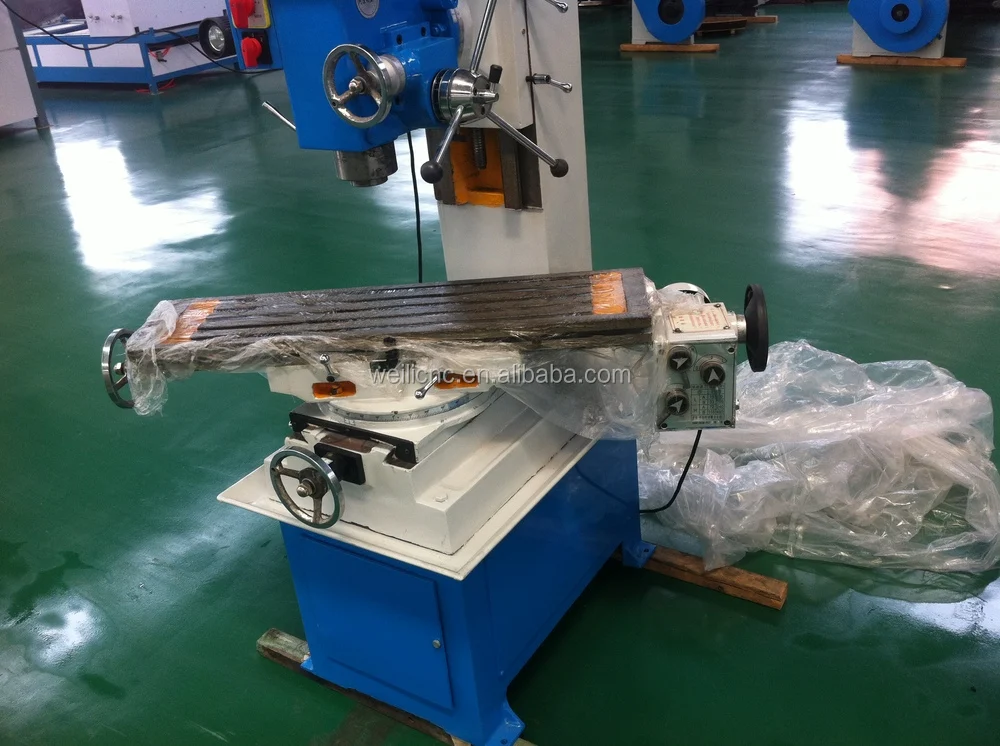
I'm not sure what feature Chris is referring to as a swivelling bed? Andrew Really annoying, I can't find the picture of the ZAY7045 showing the swivel, but it appeared to be a simpler version of this machine:
Or have I got it wrong again? Dave |
| Chris Mate | 19/01/2022 13:27:17 |
| 325 forum posts 52 photos | Disclaimer:I got a bit confused if I google the axis explanations, so correct me if I am wrong. Note-2: Edited By Chris Mate on 19/01/2022 13:48:44 Edited By Chris Mate on 19/01/2022 14:01:30 |
| JasonB | 19/01/2022 13:43:37 |
25215 forum posts 3105 photos 1 articles | X is the side to side movement along the table Y is front to back X is up and down |


Please login to post a reply.
Magazine Locator
Want the latest issue of Model Engineer or Model Engineers' Workshop? Use our magazine locator links to find your nearest stockist!
Sign up to our Newsletter
Sign up to our newsletter and get a free digital issue.
You can unsubscribe at anytime. View our privacy policy at www.mortons.co.uk/privacy
Latest Forum Posts
- *Oct 2023: FORUM MIGRATION TIMELINE*
05/10/2023 07:57:11 - Making ER11 collet chuck
05/10/2023 07:56:24 - What did you do today? 2023
05/10/2023 07:25:01 - Orrery
05/10/2023 06:00:41 - Wera hand-tools
05/10/2023 05:47:07 - New member
05/10/2023 04:40:11 - Problems with external pot on at1 vfd
05/10/2023 00:06:32 - Drain plug
04/10/2023 23:36:17 - digi phase converter for 10 machines.....
04/10/2023 23:13:48 - Winter Storage Of Locomotives
04/10/2023 21:02:11 - More Latest Posts...
- View All Topics
Support Our Partners


Shopping Partners
Subscription Offer

Latest "For Sale" Ads
- Reeves** - Rebuilt Royal Scot by Martin Evans
by John Broughton
£300.00 - BRITANNIA 5" GAUGE James Perrier
by Jon Seabright 1
£2,500.00 - Drill Grinder - for restoration
by Nigel Graham 2
£0.00 - WARCO WM18 MILLING MACHINE
by Alex Chudley
£1,200.00 - MYFORD SUPER 7 LATHE
by Alex Chudley
£2,000.00 - More "For Sale" Ads...
Latest "Wanted" Ads
- D1-3 backplate
by Michael Horley
Price Not Specified - fixed steady for a Colchester bantam mark1 800
by George Jervis
Price Not Specified - lbsc pansy
by JACK SIDEBOTHAM
Price Not Specified - Pratt Burnerd multifit chuck key.
by Tim Riome
Price Not Specified - BANDSAW BLADE WELDER
by HUGH
Price Not Specified - More "Wanted" Ads...
Get In Touch!
Do you want to contact the Model Engineer and Model Engineers' Workshop team?
You can contact us by phone, mail or email about the magazines including becoming a contributor, submitting reader's letters or making queries about articles. You can also get in touch about this website, advertising or other general issues.
Click THIS LINK for full contact details.
For subscription issues please see THIS LINK.
Digital Back Issues


Donate

 Register
 Log-in
Model Engineer Magazine
- Percival Marshall
- M.E. History
- LittleLEC
- M.E. Clock

ME Workshop
- An Adcock
- & Shipley
- Horizontal
- Mill

Subscribe Now
- Great savings
- Delivered to your door

Pre-order your copy!
- Delivered to your doorstep!
- Free UK delivery!
All Forum Topics > Beginners questions > 1st milling with the ZAY7045 Milling machine-Question