Forum sponsored by:

Gas engine
| bricky | 01/10/2021 15:43:08 |
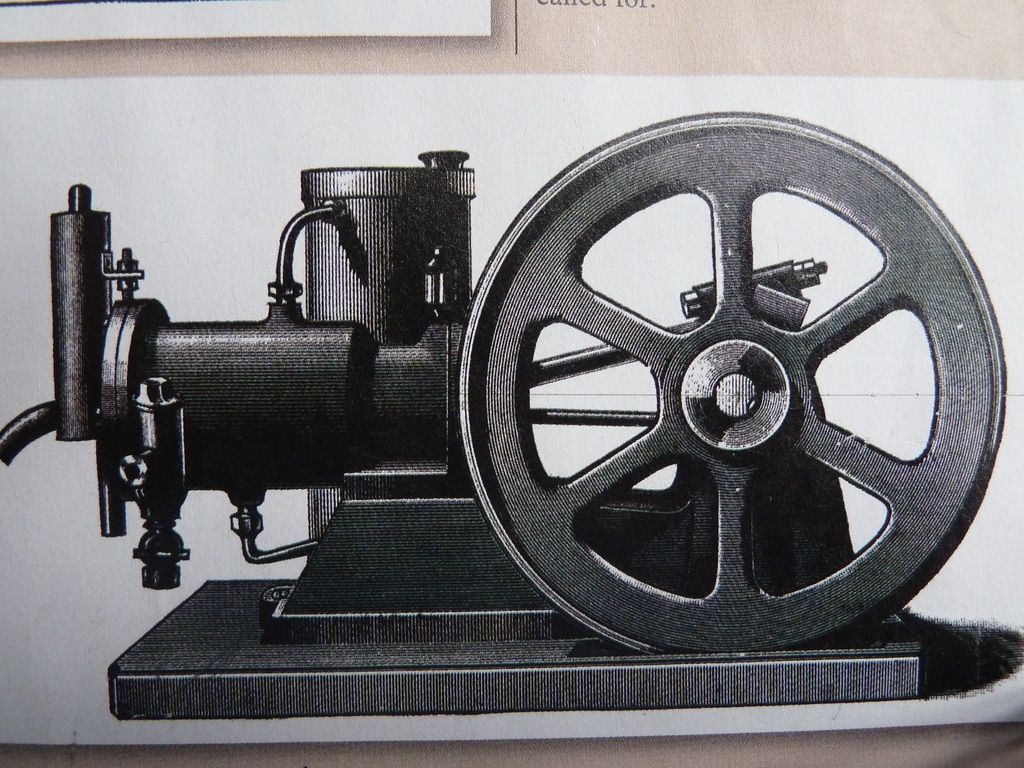
| 627 forum posts 72 photos | I bought a Stationary Engine magazine June 2021 No567,In which was an article by George Barrett on THe Boys Own Paper Engine.This gas engine was designed by Henry Fuller Hobden in 1895 and was designed to be made on a 3.5' gap bed lathe.Mr barrett was seeking information on this engine as he wished to build it,I too am interested in this engine .I can't get make patterns for this engine as it requires a water jacket and my knowledge of patter makeing is limited,also there is no casting factory nearby.I have done a full size drawing of this engine from the illustrations so that I would be able to make it in stock material.The main question I have is that the given dimention for the combustion chamber at TDC is 1.375" and the diameter is 1.5" with a .5"gas inlet vave on the side of this chamber, this chamber seems huge.The air and gas are forced into an external 4"*.375"verticle steel tube on the cylinder head which is heated by a flame from below .The gas is forced into this hot tube and causes the ignition.The other question is what type of gas to use.I can make it but what is the opinion of others as to it working.In 2016 I think it was raised by George Barrett on the forum but I can't find the coments made at the time. Frank Edited By JasonB on 05/10/2021 07:29:54 |
| MichaelR | 01/10/2021 16:01:37 |
 528 forum posts 79 photos | Try this Link it may be what you are looking for. Edited By MichaelR on 01/10/2021 16:02:35 |
| JasonB | 01/10/2021 16:07:43 |
 25215 forum posts 3105 photos 1 articles | Sounds about right, the hot tube engines I have made are quite low compression. I run mine on Propane, you will need to design an inlet valve that shuts off the gas when the valve is closed which is not too hard to do and also regulate this down to a very low flow. The same gas supply can be teed off to heat the hot tube, the smallest Sievert burner is commonly used for this. Hot tube from stainless steel and drill it so the wall is quite thin, make provision to adjust the height of the burner as the position of the "hot" part of the tube gives your ignition timing. |
| JasonB | 01/10/2021 16:43:11 |
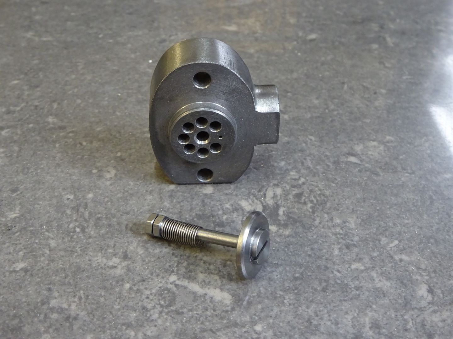
25215 forum posts 3105 photos 1 articles | You may also want to try asking on this FB group for small power engines regarding your 1/2" inlet hole, if you make a block like this where the air is drawn through all the large holes and the gas comes in at th eside and out of the single small hole you should get a reasonable gas/air ratio. The valve has a very weak spring and is drawn open by the vacuum created by the induction stroke of th episton
|
| JasonB | 01/10/2021 19:59:22 |
25215 forum posts 3105 photos 1 articles | We also discussed the subject on MEM |
| bricky | 01/10/2021 20:58:50 |
| 627 forum posts 72 photos | Thanks to all the information given,it seems that it will run and that gives me encouragement to persue this project. Frank |
| JasonB | 02/10/2021 07:19:29 |
25215 forum posts 3105 photos 1 articles | Do keep us posted with some images of your design, would also be nice to see some scans of the other original images. Having now looked through the MEM thread again the inlet would probably be better done as a turned part that can be screwed into the "tee" shaped fitting on the side of the cylinder, you could still go with teh flat type valve as shown above or a more conventional 45deg seat.
If you are going to go with a cast flywheel then Engineer's Emporium have quite a few and it's also worth contacting Graham Corry as he may have some heavy ones in the 9-10" sizes. If you go down the pattern and casting route then Purbrite have done some casting for Me and Graham recently. |
| bricky | 02/10/2021 13:07:38 |
| 627 forum posts 72 photos | Thanks Jason that valve is totaly different from the illustrated valve and yours looks simpler to make and is the way to go.I will try to get the illustrations on the post.The drawings are done full size and I cannot do cad drawing so unless I do a small scale drawings I can't post them but eventualy I will try.I am still at the stage of working out if I should proceed. Frank
|
| bricky | 03/10/2021 10:27:21 |
| 627 forum posts 72 photos | The illutration for the engine are now in my album as I have never added images to my posts I don't know how many could be incorporated and as there are 15 it might be a challenge . Frank Edited By JasonB on 04/10/2021 06:56:48 |
| JasonB | 04/10/2021 06:57:50 |
25215 forum posts 3105 photos 1 articles | Thanks for those Frank, they can all be posted into a single thread but I've added a link to the album in your post and put an image at the top of the thread. I'll have a better study of them later. |
| JasonB | 05/10/2021 07:42:58 |
25215 forum posts 3105 photos 1 articles | Having had a better look at the images it does not look too hard to make by fabrication with a few options depending on what methods you have available to join the bits - weld, Silver solder or screw and glue (JBWELD) The cylinder would need to have a separate liner fitted to create the water space and this would still be an option with a cast outer and a lot easier than the cored casting shown. The liner is basically just a tube turned from cast iron with a small flange at the head end, a matching recess in the cylinder flange takes the liners flange. Holes at either end of the cylinder are a food fit on the liner OD but you undercut the middle to form the water space. As you mentioned the gas/air inlet valve as drawn would be quite a challenge with it's gas valve seating deep inside the casting and also getting the distance between the two valves correct though without a key to the captions it's hard to tell if there is any adjustment in there. Not sure how well the simple burner shown would work as it would need some testing to get the air/gas mix right so you don't get an orange flame, maybe rig up a Sievert for initial testing of the engine and I'd make the hot tube thinner say 7/32 or 1/4" OD with 4mm bore. |
| Nigel McBurney 1 | 05/10/2021 10:09:51 |
 1101 forum posts 3 photos | I run 2 Gardner engines an no 0 and a no 1 on propane and a small National ,I use a two regulator set up one for the engine ,the other for the hot tube. each regulator has a pressure gauge,I find 3/4 to 11/2 psi works, the burner uses gas pressure of about 3 psi.the gas air mixture is critical ,too rich or too weak and then the mixture will not fire,unlike a petrol engine which will run with a rich or weak air fuel mixture though with lots of smoke or pops and bangs. The separate gas supply for the burner is used as the induction stroke from the engine can drain the gas supply and extinguish the tube burner. most gas engines run on three valves ,air inlet, gas inlet,and exhaust the governing being on the operation of the gas valve ie hit and miss, my wifes Stuart 600 was designed to run on gas or petrol ,it has the usual 3 valves for operation on gas,the governor hit and missing on the gas inlet valve,when running on pertrol the governor control to the gas inlet valve is disconnected and the governor operates the carburreter slide.Be careful with very thin hot tubes they can burst so dont look directly down the tube chimney, I have seen a tube burst ,hot bits of chimney hit the shed ceiling when a friend operated his 1/2 size model and a no 0 . tough he did make very thin tubes which do run better. |


Please login to post a reply.
Magazine Locator
Want the latest issue of Model Engineer or Model Engineers' Workshop? Use our magazine locator links to find your nearest stockist!
Sign up to our Newsletter
Sign up to our newsletter and get a free digital issue.
You can unsubscribe at anytime. View our privacy policy at www.mortons.co.uk/privacy
Latest Forum Posts
- *Oct 2023: FORUM MIGRATION TIMELINE*
05/10/2023 07:57:11 - Making ER11 collet chuck
05/10/2023 07:56:24 - What did you do today? 2023
05/10/2023 07:25:01 - Orrery
05/10/2023 06:00:41 - Wera hand-tools
05/10/2023 05:47:07 - New member
05/10/2023 04:40:11 - Problems with external pot on at1 vfd
05/10/2023 00:06:32 - Drain plug
04/10/2023 23:36:17 - digi phase converter for 10 machines.....
04/10/2023 23:13:48 - Winter Storage Of Locomotives
04/10/2023 21:02:11 - More Latest Posts...
- View All Topics
Support Our Partners


Shopping Partners
Subscription Offer

Latest "For Sale" Ads
- Reeves** - Rebuilt Royal Scot by Martin Evans
by John Broughton
£300.00 - BRITANNIA 5" GAUGE James Perrier
by Jon Seabright 1
£2,500.00 - Drill Grinder - for restoration
by Nigel Graham 2
£0.00 - WARCO WM18 MILLING MACHINE
by Alex Chudley
£1,200.00 - MYFORD SUPER 7 LATHE
by Alex Chudley
£2,000.00 - More "For Sale" Ads...
Latest "Wanted" Ads
- D1-3 backplate
by Michael Horley
Price Not Specified - fixed steady for a Colchester bantam mark1 800
by George Jervis
Price Not Specified - lbsc pansy
by JACK SIDEBOTHAM
Price Not Specified - Pratt Burnerd multifit chuck key.
by Tim Riome
Price Not Specified - BANDSAW BLADE WELDER
by HUGH
Price Not Specified - More "Wanted" Ads...
Get In Touch!
Do you want to contact the Model Engineer and Model Engineers' Workshop team?
You can contact us by phone, mail or email about the magazines including becoming a contributor, submitting reader's letters or making queries about articles. You can also get in touch about this website, advertising or other general issues.
Click THIS LINK for full contact details.
For subscription issues please see THIS LINK.
Digital Back Issues


Donate

 Register
 Log-in
Model Engineer Magazine
- Percival Marshall
- M.E. History
- LittleLEC
- M.E. Clock

ME Workshop
- An Adcock
- & Shipley
- Horizontal
- Mill

Subscribe Now
- Great savings
- Delivered to your door

Pre-order your copy!
- Delivered to your doorstep!
- Free UK delivery!
All Forum Topics > I/C Engines > Gas engine