Forum sponsored by:

Allchin 1 1/2” scale Traction Engine Shaft Manufacture
| Samsaranda | 31/07/2021 16:37:05 |
 1688 forum posts 16 photos | I would value the opinions of fellow modellers, and particularly from anyone who has built the Allchin Royal Chester Traction Engine. My problem is how to manufacture the external splines on the second shaft in the gear train, the shaft is approx 5” in length and it has splines for about a 2” section. These splines are 1/8” wide and there are four spaced equally about a 17/32” diameter shaft, their purpose is to locate the sliding hub with spur gears mounted on it to effect changing the fwd speed of the machine. Unfortunately I do not have access to a broach, nor do I have the means to manufacture and use one. My first thought was to slot drill the shaft and use 1/8” key steel silver soldered in to the slots, then my thoughts progressed to a vision of the shaft ending up like a banana with all that heat applied, so I thought the key steel could be soft soldered into the slots or even use the correct engineering adhesive to secure the key steel / splines, once assembled with the sliding hub there is no way the key steel could part company with the shaft, I realise that the splines would need to be a good tight fit in the slots, or has anyone got any thoughts on this or of any other method of achieving the objective. Dave W |
| JasonB | 31/07/2021 16:48:25 |
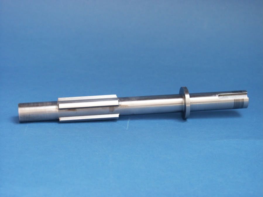
 25215 forum posts 3105 photos 1 articles | Hopefully Andrew will post his pictures of the proper way to do it. In the mean time the drawings for my 2" fowler show the method you describe with separate keys soft soldered into slots which is the way I did it.
|
| Samsaranda | 31/07/2021 16:55:23 |
1688 forum posts 16 photos | Hi Jason, many thanks for your reply it looks the way to go, your shaft looks very smart. Dave W |
| Nigel McBurney 1 | 31/07/2021 19:19:50 |
 1101 forum posts 3 photos | I made mine over 50 years ago,so without loctite or other adhesives, I milled 4 equi spaced slots and fitted mild steel keys ,they were secured by long rivets,nowadays I would use high strength Loctite, or machine the keys out of solid,which if I remember correctly W hughes suggested machine from solid in his write up in ME. |
| Clive Brown 1 | 31/07/2021 19:50:40 |
| 1050 forum posts 56 photos | W Hughes, ME vol139, wrote that some builders silver soldered the splines into milled grooves, though he didn't seem to really approve, possibly non-original. His preferred method was making a "horizontal" milling cutter from case-hardened mild steel to cut the splines on the shaft and also a matching broach, also case-hardened, with photos to prove that it worked. I'm surprised he didn't use silver steel IIRC, I used a combination of end-milling and planing in my long-suffering old Grayson lathe, with dividing via a change-wheel. Whisper it not, my splines only fit in in one position, but otherwise OK and WJH himself admits to the same, so I'm in good company. |
| Samsaranda | 01/08/2021 09:23:27 |
1688 forum posts 16 photos | Nigel & Clive thanks for your replies,I will go with Jason’s suggestion of milling slots using key steel soft soldered in place, I know that W Hughes would probably disapprove but as long as it all fits together I shall be happy, even if it’s only in one position. Dave W Edited By Samsaranda on 01/08/2021 09:24:21 |
| Andrew Johnston | 01/08/2021 17:13:18 |
 7061 forum posts 719 photos | When it came to machining the 6-sided splines on my Burrell SCC crankshafts I considered the slot 'n' key method, or using an offset endmill to form the sides of the spines and then nibbling out the space in between the splines. Neither seemed satisfactory, or prototypical. It is possible to buy commercial spline cutters, but none were available in the size needed. So I designed and made my own, from gauge plate which was hardened and tempered:
The splines were cut on a horizontal mill plus dividing head, the same setup as for gear cutting. Finished splines:
The internal splines were cut using a HSS toolbit and a slotting head with rotary table:
A length of HSS was ground on a cylindrical grinder to get the correct end radius (by measuring the diameter) and then cut in half and clearances added by hand:
The internal HSS toolbit is a couple of thou under width so final fitting of the gears to the splines was done with files. I made a test piece on scrap bar, and a messed up gear blank, to check out the process beforehand:
These are the finished splines, and outer gear:
Note that there is clearance on the inner and outer diameters, so the splines drive purely on the sides. The gears fit in all six orientations, although the shake varies from nothing to a little in the different orientations. I made a few mistakes along the way. I didn't support the middle of the crankshaft when cutting the splines. Consequently the splines vary in width by a thou or two along their length. Each gear only works on half the spline length, so they are hand fitted to that length. The inner gear goes all the way along the splines, while the outer gear will only go half way down the spline. Originally i made a set of gears with a lot of inner clearance and with a straight ended slotting tool. But they didn't look right, so I binned them and made another set. In addition I hadn't got to grips with machining EN8 at the time, so the finish on the first set of gears was poor - another reason to recycle them. Andrew |
| Zan | 01/08/2021 17:30:41 |
| 356 forum posts 25 photos | I made the cutter as indicated by Hughes, it worked perfectly, the gear hub slid on without the sleigh test bit of binding. Still got the cutter somewhere in my specials box!
|
| Samsaranda | 02/08/2021 09:44:06 |
1688 forum posts 16 photos | Andrew, as always I am impressed by your attention to detail, your methods have given me much food for thought, however I lack a horizontal mill so manufacturing options are limited, having received information on the various methods it looks like I will be going down the route of the slot-n-key method, here’s hoping that the splines index correctly. Dave W |
| JasonB | 02/08/2021 11:59:21 |
25215 forum posts 3105 photos 1 articles | As the Allchin is less than half the size of Andrews it should be possible to do it with a rotary table or dividing head provided tailstock support is added and then use the form tool in a vertical mill, you could even rough mill most of the waste away and just use the form tool to finish. |


Please login to post a reply.
Magazine Locator
Want the latest issue of Model Engineer or Model Engineers' Workshop? Use our magazine locator links to find your nearest stockist!
Sign up to our Newsletter
Sign up to our newsletter and get a free digital issue.
You can unsubscribe at anytime. View our privacy policy at www.mortons.co.uk/privacy
Latest Forum Posts
- *Oct 2023: FORUM MIGRATION TIMELINE*
05/10/2023 07:57:11 - Making ER11 collet chuck
05/10/2023 07:56:24 - What did you do today? 2023
05/10/2023 07:25:01 - Orrery
05/10/2023 06:00:41 - Wera hand-tools
05/10/2023 05:47:07 - New member
05/10/2023 04:40:11 - Problems with external pot on at1 vfd
05/10/2023 00:06:32 - Drain plug
04/10/2023 23:36:17 - digi phase converter for 10 machines.....
04/10/2023 23:13:48 - Winter Storage Of Locomotives
04/10/2023 21:02:11 - More Latest Posts...
- View All Topics
Support Our Partners


Shopping Partners
Subscription Offer

Latest "For Sale" Ads
- Reeves** - Rebuilt Royal Scot by Martin Evans
by John Broughton
£300.00 - BRITANNIA 5" GAUGE James Perrier
by Jon Seabright 1
£2,500.00 - Drill Grinder - for restoration
by Nigel Graham 2
£0.00 - WARCO WM18 MILLING MACHINE
by Alex Chudley
£1,200.00 - MYFORD SUPER 7 LATHE
by Alex Chudley
£2,000.00 - More "For Sale" Ads...
Latest "Wanted" Ads
- D1-3 backplate
by Michael Horley
Price Not Specified - fixed steady for a Colchester bantam mark1 800
by George Jervis
Price Not Specified - lbsc pansy
by JACK SIDEBOTHAM
Price Not Specified - Pratt Burnerd multifit chuck key.
by Tim Riome
Price Not Specified - BANDSAW BLADE WELDER
by HUGH
Price Not Specified - More "Wanted" Ads...
Get In Touch!
Do you want to contact the Model Engineer and Model Engineers' Workshop team?
You can contact us by phone, mail or email about the magazines including becoming a contributor, submitting reader's letters or making queries about articles. You can also get in touch about this website, advertising or other general issues.
Click THIS LINK for full contact details.
For subscription issues please see THIS LINK.
Digital Back Issues


Donate

 Register
 Log-in
Model Engineer Magazine
- Percival Marshall
- M.E. History
- LittleLEC
- M.E. Clock

ME Workshop
- An Adcock
- & Shipley
- Horizontal
- Mill

Subscribe Now
- Great savings
- Delivered to your door

Pre-order your copy!
- Delivered to your doorstep!
- Free UK delivery!
All Forum Topics > Workshop Techniques > Allchin 1 1/2” scale Traction Engine Shaft Manufacture