Forum sponsored by:

Harrison L5A tool post mod
| Francis Greenslade | 03/05/2021 23:57:58 |
| 4 forum posts 3 photos |
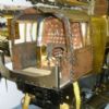
hi All, Any recommendations for fitting a QCTP to my Harrison L5A. I would like to do the least amount of modifications as possible. The main bolt has a cone which can be removed but it works really well locking the original tool post down as it is.. I was wondering if there is a QCTP with internal cone that would fit on it? I tried removing the cone and just locking the 4 sided turret down on the flat surface but it doesn't hold as well as the cone. Really all I want an adjustable way of centering my tools without having to use packers. Any advice welcome. cheers Frank Greenslade New Zealand
Moderator edit - rotated photos. Edited By SillyOldDuffer on 04/05/2021 09:47:50 |
| martin haysom | 04/05/2021 08:56:02 |
 165 forum posts | make one ??? |
| Clive Foster | 04/05/2021 09:08:15 |
| 3630 forum posts 128 photos | Frank No way of accommodating the cone inside a standard QC post. They are usually harder than a woodpeckers beak so modification isn't realistically possible. Nearest you can get to the cone for rotational location is the Dickson style pin that can be dropped into suitable holes. As you have a T slot mount its not too difficult to make a new full-lengthTee nut to take a new pin sized to match your new tool-post. Picture shows one I made a while back for my P&W model B.
I screwed and glued together two standard flat bar sections to make the Tee nut. Post screwed and loctighted in with a collar matching the recess in the Dickson T2 tool post screwed down to further locate it. Index holes provided for the tool post pin even though I never use it. I put a couple of short hex socket grub screws in to further locate the Tee nut. I made sure the top of the slide was flat so the post holds without heaving up on the spanner. I have a thin alloy shim between post and slide to equalise the tool post heights on my two lathe so I can swop tooling. The alloy shim improves grip. Do remember that the approved technique is to make the stud undersize so its a slack fit in the tool post bore and use a top hat style spacer made a nice sliding, shake free, fit in the bore and on the stud to centralise things. Official parts seem to be about 1/4" thick on the outer rim that the nut clamps down on with about 3/8" going down into the bore. Presumably this avoids issues should the stud not be truly vertical. My rim is about 1" deep to clear the tool holder studs so I could use an ordinary spanner until I got round to making a dedicated box spanner. Worst issue with a QC system for ordinary folk is the cost of all the holders needed to keep the tools you use ready for action. Most folk seem to reckon 12 would be nice! I have rather more. Hafta say that if I were in your position of not already having a QC system I'd seriously look into organising rapid change block tool posts. Shimming tools to centre is much less of a faff when you cna do it on the bench by measurement. Much cheaper than a QC system as 2 and 4 way blocks can be built up from standard sections screwed and glued together. Easy way to make a rapid change block is to make the stud free rotating with a large hollow castellated "nut" screwed into the top with a tommy bar going through both nut and and stud. Half a turn will release things sufficiently for the bar to be withdrawn so the block can be lifted off and another one with a different load of tools fitted. and locked with an opposite half turn of the bar. May be easier to make the tool post stud in two sections with just the top part turning. Clive Edited By Clive Foster on 04/05/2021 09:13:29 |
| DC31k | 04/05/2021 09:08:53 |
| 1186 forum posts 11 photos | Remove the rusty half nut and the full nut below it. The cone will then come off, leaving the stud screwed into the T-nut in the slide. Remove T-nut and stud, leaving bare top slide casting. This is your starting point. Make new T-nut, stud and centring bush if required to suit chosen QC toolpost. If the dimensions suit, you can make the upper thread on the stud the same as you already have so you can reuse the clamping handle. If you want to seamlessly swap between the current one and a QCTP, you need to make a quick change toolpost post. |
| Francis Greenslade | 04/05/2021 09:09:13 |
| 4 forum posts 3 photos | There's a challenge Yea ... I have to have a think about that. How would I make an adjustable tool holder that bolts into the 4 sider turret? that's what I want! |
| Nigel Graham 2 | 04/05/2021 09:14:22 |
| 3293 forum posts 112 photos | That coned fitting will almost certainly be special to Harrison so you won't find a QCTP to suit if. My Harrison's L5 has a plain top surface to the compound slide, and to fit a QCTP I found I needed simply make a bush to accommodate the tool-post stud and tool-holder body. I would guess that the cone will come off the stud, giving you a plain mounting surface and stud to hold a quick-change post with appropriate bushes as I did. Or replace the stud if the new tool-post needs a smaller diameter. Keep the removed parts so they can be put back in future if ever needed. On mine, I can easily swap back to the original clamp I need to use a tool too large for the QCTP. |
| Clive Foster | 04/05/2021 09:23:49 |
| 3630 forum posts 128 photos | Francis Armstrong, J&S, Williams, Denford et al tool bit holders set the tool bit pointing up at small angle so sliding the bit in and out alters the tip height. Disadvantage is that they project a bit further from the tool block than a simple welded shank tool. Advantage is that there is no waste from grinding top rake. Either use as is or reduce it when needed for brass et al. No reason why you couldn't do the same with slot style toolholder having a lug on the side to fit in the 4 way post. Just cut the slot at a suitable upwardly pointing angle. Basically the same as the holder for the T type parting tools but sloping upwards a bit. I think the Armstrong et al bit holders mentioned previously use something around 7° up tilt. Or just switch to carbide inserts as the tip height is fixed by the holder. Clive
|
| Francis Greenslade | 04/05/2021 09:29:58 |
| 4 forum posts 3 photos | Hi all, thanks for your replies so far. Please excuse the random reply as I'm new to forums. ...first post. Clive...I like your work, it looks great! DCK13... yip . I like your logical approach and reusing the handle is good advice. Martin. ... I don't have a mill.hmm... you can make everything with a lathe right? I really would like an adjustable tool holder that I can bolt in the 4 sider. The original 4 sider works beautifully . I saw a post somewhere where one had been restored. It has a spring loaded indexing pin which doesn't work ATM. Good for production jobs they said.
|
| norm norton | 04/05/2021 10:08:25 |
| 202 forum posts 10 photos | Frank, It is going to be expensive getting a large number of QC tool holders. I have some twenty tools lined up on a shelf above my Harrison 140, each sitting on their own packing piece, specifically milled for height for that tool (sorry, I realise you don't have a mill). OK, took me a day to do them all but now that's it, and very low cost. That four sided head is a delight to use and quicker to swap between four tools than QC holders. The indexing balls under my tool post work very well and if I rotate from one tool back to my DRO set facing cutter it is typically within a thou of the correct diameter - about the same as QC tool swaps. Norm |
| Francis Greenslade | 04/05/2021 23:42:44 |
| 4 forum posts 3 photos | hi All, Thanks so much for all your advice. I'm blown away by knowledge and experience here! I guess I'm leaning towards Norm's advice and have machined packers for each tool. Then I get to keep it original and cheaper. What is the best way to determine packer thickness?....To date I have been eyeballing my tool height against the tailstock centre. If I am to get someone to mill the packers I will have to give them an accurate measurement. cheers
|
| John Baron | 05/05/2021 07:46:05 |
 520 forum posts 194 photos | Hi Francis, Guys, I think that the cone is used to clamp the "T" slot, so removing it will mean you need something to replace it ! A flat steel plate would work, and give you a surface to mount another type of tool block. Personally I made my own new toolpost and tool holder to replace the QCTP and four way tool block. A relatively simple job, but you would need a mill to cut the tool holder slot. Even that could be done on the lathe but I wouldn't recommend milling using the lathe. This is a picture of mine !
It is called a "Norman Patent" tool post. I also made one for the rear of the cross slide, mainly for a parting blade but the tool holders are interchangeable so I can use either at the front or rear. No shims needed to set tool height either. The silver cap head screw sets the height of tool.
I made this height gauge to use to set the tool on centre. The underside of the cap is used for the front and the top of the bar used to set the parting blade height. Moe pictures in my albums. HTH. |
| Clive Foster | 05/05/2021 09:23:56 |
| 3630 forum posts 128 photos | Francis There are many designs of tool tip height setting systems out there. Possibly the simplest "quick and dirty" one is a simple block to sit on the bed with the bent end of a scriber screwed into it so the point is exactly on centre height. Needs a three piece scriber but if you are willing to sacrifice the bent end cost is basically nowt. Most common designs have a base and stout post with a pair of flat bottomed indicator pointers affixed to it. One pointer is set so its bottom is at centre line when the base is on the lathe bed and the other, set lower, is on centre line when the base is on the cross slide. Normal practice is to make the indicator pointers sharp so they can be used to scribe witness lines at centre height on a job. Not a feature i've ever felt the need for but most well respected correspondents consider it desirable. I prefer an optical version having an adequately thick transparent plastic plate is held vertically on a base with witness lines scribed on both sides at using a sharp centre. One set of lines is made with the base on the lathe bed, the other with it on the cross slide. Some creativity is needed to do the lathe bed reference lines. Unfortunately I can't remember how I did mine. Having lines on both sides means that when looking horizontally through the plate you see only one line so tip height can be judged from some distance away. I have a mirror that can be mounted onto mine so I can look down rather than through. Most of the time I just work off the front line but sometimes when setting up mid job the device cannot be got close too the tool tip. My perspex plate is only 5 mm thick which is on the thin side, 10 mm would be better. I'll change it if a piece of 10 mm ever comes my way but what I have works well enough.
Using the mirror
Lines
Although effective all these versions of the conventional tool height gauge work best with QC and similar screw height setting systems. If you are using packing it would be much nicer if the actual tip height could be measured and packing stacks made to the correct height rather than trial and error. I have seen depth micrometers and verniers set-up to do the job but usually only as temporary expedients. Back in the day dedicating a proper measurement instrument to the job was unaffordable for Home Workshop and Model Engineer folk. These days perfectly adequate dial gauges can be got quite inexpensively so fitting one with an "elephants foot" and on a suitably sturdy stand with fixed height arm would work well to measure actual tip height. Dial gauges have a small ball end screwed into the probe as standard so measurements can be accurately mate at a point even if the surface is imperfect. The "elephants foot" is an alternative end fitting able to measure edges and the like where aligning a small ball end is impractical. Typically 1/2" to 1" diameter made very flat and set exactly at right angles to the dial gauge probe. Can be bought as accessories but esily made with a bit of care. 1/2" will be fine. Clive
Edited By Clive Foster on 05/05/2021 09:25:49 |
| Nigel Graham 2 | 05/05/2021 10:12:08 |
| 3293 forum posts 112 photos | You could also make a simple contact height-gauge that uses two discs, mounted perhaps on a scribing-block post, such that you adjust the tool to just touch the under or top disc surface as appropriate. When sighting the tool against anything (often, I use either of the centres), I find it helps to use a white card background. |
| ega | 05/05/2021 11:09:24 |
| 2805 forum posts 219 photos | Posted by norm norton on 04/05/2021 10:08:25:
Frank, It is going to be expensive getting a large number of QC tool holders. I have some twenty tools lined up on a shelf above my Harrison 140, each sitting on their own packing piece, specifically milled for height for that tool (sorry, I realise you don't have a mill). OK, took me a day to do them all but now that's it, and very low cost. That four sided head is a delight to use and quicker to swap between four tools than QC holders. The indexing balls under my tool post work very well and if I rotate from one tool back to my DRO set facing cutter it is typically within a thou of the correct diameter - about the same as QC tool swaps. Norm A refreshing change to find a champion of the indexed four way toolpost as opposed to the pick-off QCTP! At the end of GHT's description of his tool posts for the Myford he set out the results of a series of tests for repeatability showing a maximum deviation of about four tenths of a thou. |
| norm norton | 05/05/2021 20:34:31 |
| 202 forum posts 10 photos | A refreshing change to find a champion of the indexed four way toolpost as opposed to the pick-off QCTP!
At the end of GHT's description of his tool posts for the Myford he set out the results of a series of tests for repeatability showing a maximum deviation of about four tenths of a thou. Thank you ! must tell my wife somebody finds me refreshing Was GHT describing a four-tenths deviation for a QCTP or an indexed head? I have one of the small QCTPs on my Myford S7. It is possible to get slightly better than one thou variation IN DIAMETER ON THE JOB changing tools, but only if the head and holder are scrupulously cleaned (especially if turning brass) and you adopt a repeatable style of dropping the holder in and tightening it. Typical tool swaps are a thou, i.e. half a thou in tool absolute position. Norm |
| ega | 05/05/2021 21:03:11 |
| 2805 forum posts 219 photos | Norm: GHT's tests were on two of his own four way indexing tool posts and, for comparison, on the Myford ditto: four tenths for the "worse" GHT and twelve tenths for the Myford. GHT's test job (in brass) involved both cross slide movements and tool swaps but, of course, the latter would not be prone to chip contamination. Details in his articles from ME or his Workshop Manual. One of his reasons for favouring the four way was that he professed never to have met any QCTP user with more than four tool holders; I gather that there are some today with ten times that number! |
| norm norton | 06/05/2021 10:15:13 |
| 202 forum posts 10 photos | Thanks, that is interesting, and confirms my imprecise and random findings. While the four-way works nicely on the bigger Harrison, there are several reasons (for me) why the QC seems to suit a small Myford. Enough toolholders? I have a dozen and I am continually swapping tools in and out of them! |
| Brian Baker 1 | 06/05/2021 12:42:16 |
 229 forum posts 40 photos | Greetings Francis, I think you will have to match the taper yourself, I have never seen any tapered tool posts like the one you show. On my Harrison 1100, I fitted the usual quick change tool post onto of the flat platform when the 4 way was removed, and which I have never used since. As a bonus, I made a disc which when fitted on the toolpost spindle, took a spare Myford sized quick change tool post, so that I could use all my Myford sized tools in their holders as well. You can never have enough QC toolholders! Regards Brian B |


Please login to post a reply.
Magazine Locator
Want the latest issue of Model Engineer or Model Engineers' Workshop? Use our magazine locator links to find your nearest stockist!
Sign up to our Newsletter
Sign up to our newsletter and get a free digital issue.
You can unsubscribe at anytime. View our privacy policy at www.mortons.co.uk/privacy
Latest Forum Posts
- hemingway ball turner
04/07/2025 14:40:26 - *Oct 2023: FORUM MIGRATION TIMELINE*
05/10/2023 07:57:11 - Making ER11 collet chuck
05/10/2023 07:56:24 - What did you do today? 2023
05/10/2023 07:25:01 - Orrery
05/10/2023 06:00:41 - Wera hand-tools
05/10/2023 05:47:07 - New member
05/10/2023 04:40:11 - Problems with external pot on at1 vfd
05/10/2023 00:06:32 - Drain plug
04/10/2023 23:36:17 - digi phase converter for 10 machines.....
04/10/2023 23:13:48 - More Latest Posts...
- View All Topics
Support Our Partners


Shopping Partners
Subscription Offer

Latest "For Sale" Ads
- Reeves** - Rebuilt Royal Scot by Martin Evans
by John Broughton
£300.00 - BRITANNIA 5" GAUGE James Perrier
by Jon Seabright 1
£2,500.00 - Drill Grinder - for restoration
by Nigel Graham 2
£0.00 - WARCO WM18 MILLING MACHINE
by Alex Chudley
£1,200.00 - MYFORD SUPER 7 LATHE
by Alex Chudley
£2,000.00 - More "For Sale" Ads...
Latest "Wanted" Ads
- D1-3 backplate
by Michael Horley
Price Not Specified - fixed steady for a Colchester bantam mark1 800
by George Jervis
Price Not Specified - lbsc pansy
by JACK SIDEBOTHAM
Price Not Specified - Pratt Burnerd multifit chuck key.
by Tim Riome
Price Not Specified - BANDSAW BLADE WELDER
by HUGH
Price Not Specified - More "Wanted" Ads...
Get In Touch!
Do you want to contact the Model Engineer and Model Engineers' Workshop team?
You can contact us by phone, mail or email about the magazines including becoming a contributor, submitting reader's letters or making queries about articles. You can also get in touch about this website, advertising or other general issues.
Click THIS LINK for full contact details.
For subscription issues please see THIS LINK.
Digital Back Issues


Donate

 Register
 Log-in
Model Engineer Magazine
- Percival Marshall
- M.E. History
- LittleLEC
- M.E. Clock

ME Workshop
- An Adcock
- & Shipley
- Horizontal
- Mill

Subscribe Now
- Great savings
- Delivered to your door

Pre-order your copy!
- Delivered to your doorstep!
- Free UK delivery!
All Forum Topics > Manual machine tools > Harrison L5A tool post mod