Forum sponsored by:

Boxford STS Screwcutting Clutch
| Graham Meek | 11/02/2021 14:34:46 |
| 714 forum posts 414 photos | On Saturday last I was going through my files and deleting those which I deemed as dead, or of no further use. As luck would have it Trevor Steele sent me an email on Monday on the above Screwcutting Clutch which he has just completed. Looking at the date on the back-up file in AutoCAD, (which luckily had not got deleted), that date says 2016. I have an uncanny feeling that was when my computer was replaced and the actual design date goes back to before I retired in 2012. It seems the Lockdown has brought this version of the clutch to fruition. Thus thanks to Trevor we have another version of this attachment, and hopefully in due course Trevor will write this up for others to enjoy.
Trevor has sent me some more photographs and in due course I will add more details. I had also better add that I have Trevor's permission to post these photographs on the Forum. Regards Gray, |
| James G 1 | 12/02/2021 13:09:46 |
| 10 forum posts 1 photos | That looks great! I would be most interested in any and all details of this mechanism. I have been scratching my head trying to figure a way of doing this internally to the headstock using a dog clutch on the feed and feed reverse gears. This looks like a very neat solution. I think it will apply to other lathes in this series as well such as the 280. |
| Steviegtr | 12/02/2021 14:57:35 |
 2668 forum posts 352 photos | What a neat looking device. I don't need said device but what an ingenious method. Hope to see more pics of this. Steve. |
| Graham Meek | 12/02/2021 15:12:46 |
| 714 forum posts 414 photos | Hi James, Trevor has made some alterations to my original design. Having the machine in front of you makes things a whole lot easier. He has also added DU lined bushes, where I had originally fitted Oilite bearings. Apparently Boxford use these instead of Oilite, something I did not know, but it makes for a more compact unit. Hi Steve, I have to get to grips with downloading some photographs from the Clouds. My forte is mechanical things not Computers as some of you may have guessed, but I will get there eventually. Regards Gray, |
| Jeff Dayman | 12/02/2021 15:58:43 |
| 2356 forum posts 47 photos | Great job by Trevor on the clutch, and many thanks to you Graham for the series of screwcutting clutch designs you have contributed over the years to the hobby. Well done! |
| Gavlar | 12/02/2021 16:15:56 |
| 119 forum posts 1 photos | I'm gong to ask what may be a stupid question, but what is a screwcutting clutch for? I understand how usefull a clutch might be when surfacing but I thought when screw cutting the leadscrew and spindle mesh should be fixed with no possibility of any slip. |
| Clive Foster | 12/02/2021 16:54:04 |
| 3630 forum posts 128 photos | Screwcutting clutches are single tooth dog clutches running at spindle speed, located before the screwcutting drive gear train, operated by a fast action knock out trip. The trip is set to release the clutch at the end of the thread thus stopping the leadscrew from turning. Because the leadscrew is stationary the half nuts can be disengaged, the saddle moved back to the beginning of the thread, and the half nuts re-engages for the next pass without upsetting anything. The clutch has only one dog so the drive always restarts at exactly the same relationship between spindle rotation, drive train and leadscrew as when the clutch was tripped. Hence the next threading pass picks up perfectly on the thread. The effect is exactly as if the lathe were reversed to drive the saddle back to the start of the thread without disengaging the half nuts. Generally its more convenient not to have to reverse the lathe between passes. Its especially useful when cutting metric threads on an imperial lathe or imperial threads on a metric lathe because normally the half nuts cannot be disengaged between passes without loosing thread registration. Also handy for power feeding up to a step. My Pratt & Whitney B has one as standard. Its great! Clive |
| James G 1 | 12/02/2021 18:00:54 |
| 10 forum posts 1 photos | To follow up on the previous excellent description, the most straightforward arrangement is to have the dog clutch turning at spindle speed. I believe that the shaft where the dog clutch is located must not be running any faster than spindle speed, as this allows for re-engagement at incorrect relative positions. In the general case, a dog clutch located on a shaft which is running more slowly than the spindle will not work correctly either. This is why a clutch located on the leadscrew will not suffice. However, if the shaft with the dog clutch is rotating more slowly than the spindle by a ratio of 1/N, where N is a whole number, then I think it will work. e.g. if the dog clutch shaft turns at 1/3 of spindle speed then all will be well. However dog clutch running at say 2/5 of spindle speed will not work. The above is my understanding from reading - particularly Martin Cleeve's excellent book. The Boxford 280 and similar lathes have a built-in reduction in speed of 1/3 from spindle to the first accessible shaft of the feed train, hence my interest in the niceties!
|
| Graham Meek | 12/02/2021 18:17:04 |
| 714 forum posts 414 photos | The Screwcutting Dog Clutch, is fitted to high end Toolmakers lathes. Once the stops are set for the length of thread and the correct thread selected. All the operator has to do after engaging the half nuts, (no need to disengage until finished), is put on a cut. Throw the operating lever for the dog clutch in the direction required and wait for the carriage to stop. Withdraw the lathe tool, (usually by using the cross-slide or a retracting toolholder), and throw the operating lever in the opposite direction whereby the carriage will return to the start position. Returning the lathe tool using the cross-slide or retracting tool holder, another cut is put on and the process repeated until the thread is finished. In the hands of a skilled operator cutting a short thread by this method usually takes as long as it does to write this post. (There are several videos of the Meek Clutch out there) Regards Gray, Edited By Graham Meek on 12/02/2021 18:18:23 |
| Gavlar | 12/02/2021 19:12:32 |
| 119 forum posts 1 photos | Ah, that makes sense. I wasn't thinking along those lines at all. Now I want one! Thank you. |
| not done it yet | 12/02/2021 19:16:31 |
| 7517 forum posts 20 photos | after engaging the half nuts, (no need to disengage until finished), That makes it so much easier for cutting metric threads on an imperial lathe (and vice versa)? Particularly good for those with three phase converters, I would guess? |
| Graham Meek | 12/02/2021 19:39:43 |
| 714 forum posts 414 photos | Posted by not done it yet on 12/02/2021 19:16:31:
after engaging the half nuts, (no need to disengage until finished), That makes it so much easier for cutting metric threads on an imperial lathe (and vice versa)? Particularly good for those with three phase converters, I would guess? That is the beauty of this attachment, it does not need any motor reversing and depending on the thread being screwcut the threads can be cut at more reasonable turning speeds. As an example I was recently cutting an 8mm diameter by 1 mm pitch thread in Silver Steel at 200 rpm. While 0.5 mm pitches for my steam wagon unions, in Brass, were screwcut at 400 RPM. In theory there should be no limit to the RPM, but a little bit of sympathy for the unit is required, unless the reader likes to re-make his or her screwcutting clutch on a fairly regular basis. Regards Gray, Edited By Graham Meek on 12/02/2021 19:40:15 |
| Pete. | 13/02/2021 00:01:54 |
 910 forum posts 303 photos | Graham, someone mentioned in another thread you have a book of workshop projects, is this in your book? |
| Graham Meek | 13/02/2021 12:00:04 |
| 714 forum posts 414 photos | Posted by Pete. on 13/02/2021 00:01:54:
Graham, someone mentioned in another thread you have a book of workshop projects, is this in your book? Hi Pete, This Boxford Dog clutch was built by Trevor, to an initial design by me. He has made detail changes to the design because he has the lathe in front of him. I have copies of the drawings but I am not at liberty to release them without his OK. The clutch contained in The Book is for the Myford Super 7 which I originally designed back in the 1980's. For the purposes of any article I like to build the item being put forward, so in this case I will not be writing about this version. Writing articles this way I know they will work, so for the S7 version, a further attachment was built. Assistance was given by Ken Willson (KWIL) and Tony Pratt during this build, as I had spares left over from the initial build in 1980. Their input was invaluable and led to the use of composite and plastics for the idler gears instead of Phos Bronze. I have suggested to Trevor that an article on this particular clutch would probably be welcome among the Boxford users. He is open to the idea and given time he may well produce an article. My writing career started following a request for constructional details on my Myford Handwheel Dial by the Editor of EiM, so who knows. Regards Gray,
|
| Pete. | 13/02/2021 23:44:39 |
910 forum posts 303 photos | Hi Graham, Thanks for response, well Trevor did a very nice job, I'm sure quite a few people would be interested in drawings, I'm not subscribed to the magazine if that's where it would be published, but would definitely buy a copy with an article on this project, a heads up if he does decide to do so would be appreciated, thanks. |
| Graham Meek | 15/02/2021 11:32:54 |
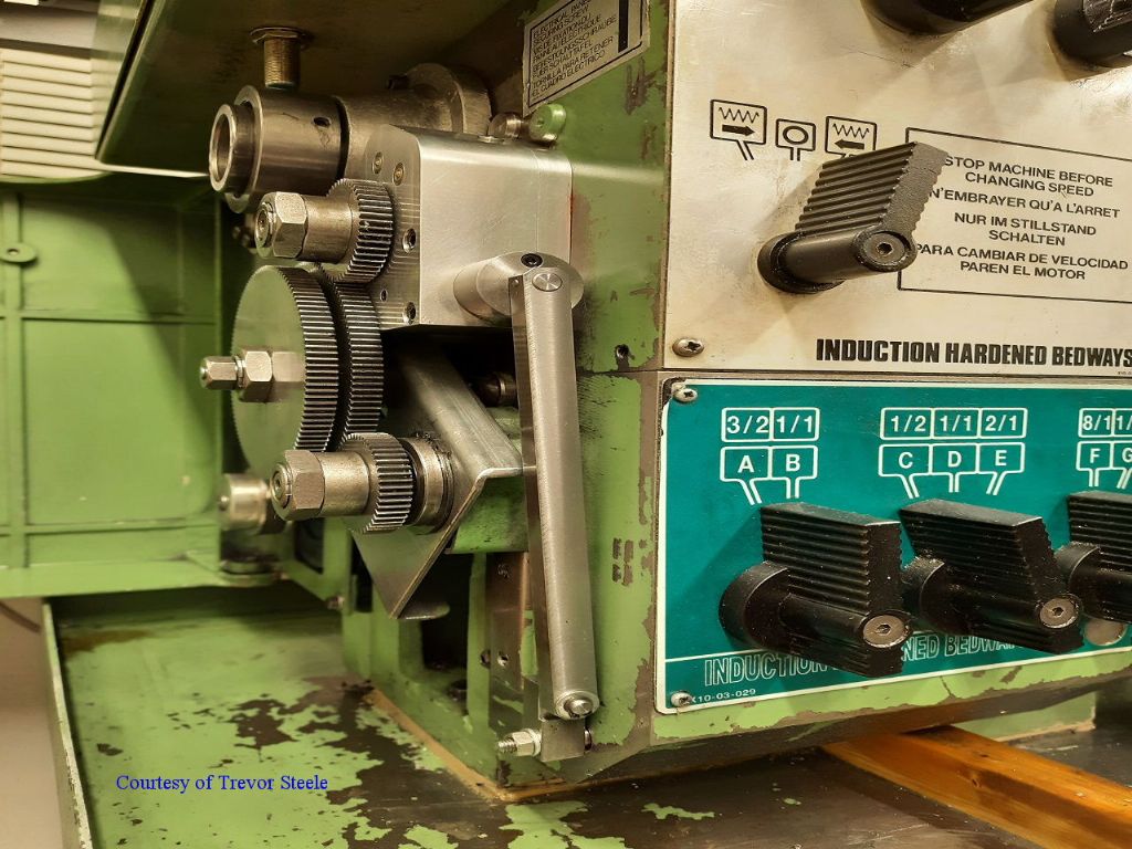
| 714 forum posts 414 photos | Here are a few more of Trevor's photographs, starting with the Operating Handle which Trevor has arranged more conveniently at the Headstock end.
The Stop Rod passes through a bar attached to the carriage, the manufacture involves a bit of sculpting to get it to fit around the Leadscrew guard support bracket.
The outer end of the Stop Rod is supported in a Bearing Block. This was where I had originally designed to place the Operating Handle.
Finally a end on view to show how well the clutch gearbox fits in the space available. Again Trevor had to make changes to my original design in order to miss the Quadrant bracket.
I will add a few shots of the internals later this week hopefully. Regards Gray, Edited By Graham Meek on 15/02/2021 11:33:55 |
| Pete. | 15/02/2021 13:14:32 |
910 forum posts 303 photos | Thanks for taking the time to post those photos, what a brilliant set up, I hope you let Trevor know his work is much admired, and look forward to seeing more. |
| Clive Foster | 15/02/2021 15:39:42 |
| 3630 forum posts 128 photos | Trevor has indeed made a very nice job of this. The bolt on nature of the brackets rather than having integrated castings are the only thing that show its a modification, not factory fit. From experience with my Pratt & Whitney B 12 x 30, which has a single tooth dog clutch as standard, I'd say that making the stop dogs with an integrated fine threaded adjuster has advantages when needing to set up just so. On the P&W simply sliding the dog along the rod becomes finicky when the longitudinal stop position needs to be set to significantly better than about 50 thou / 1 mm. I generally use an old set of gauge blocks that no longer wring together for setting the throw out position. Of course the P&W is a bigger, heftier, machine with 45 or so years of use under its belt so operation isn't factory fresh. Its quite noticeable that the exact clutch operating point varies a few thou with speed. Both rotational and longitudinal. Although Hardinge claim their version of the screw cutting clutch is good up to 1,000 rpm both P&W and Holbrook agree that around 300 rpm is quite fast enough thank you. I found my first few times of screw cutting at that sort of speed was a little buttock clenching until I learned to trust the clutch. Maybe 8 tpi was a bit coarse to start with! The P&W throws out with a very positive "Bang" too. Frankly, up to a point, faster is better. It appears that Trevor keeps the metric / imperial conversion pair permanently mounted so he only has to change the gearbox input gear and put the the spacer on the other side when switching from one standard to the other. A most excellent idea which should be mandatory for anyone having to handle both metric pitch and imperial tpi. I did a similar thing many years ago on my Smart & Brown 1024. My only regret being not doing it the first time I had to switch rather than waiting until the fourth! Time to take another look at the 1024 to see if there is any way of getting such a clutch in by taking Trevors version as a starting point. Clive Edited By Clive Foster on 15/02/2021 15:41:40 |
| Graham Meek | 15/02/2021 16:09:52 |
| 714 forum posts 414 photos | Hi Clive, Over the years I have found that each lathe has to be approached as an individual case. The Myford S7 was the very first lathe I did, and one would think that fitting this clutch to the ML7 and Big Bore would be straight forward. Alas it was not, both needed a different approach, the Big Bore for instance uses a different Headstock casting to the S7. While the ML 7 has a different Tumbler Shaft arrangement It might be a good time to list the clutches so far designed. Myford S7, ML7 & Big Bore. Emco Maximat Super 11 & Compact 8 Boxford STS Sieg & Warco Mini Lathes South Bend Wabeco D6000 Clausing Atlas 618 This last lathe has many similarities with the Myford ML7 dimensionally, but because of the peculiar use of the Tumbler output gear as part of one range of the screw cutting gear train. Made this one of the most difficult lathes to do. Yet at first look it seemed to be a walk in the park. This Boxford clutch was the first to be fitted externally to the Tumbler reverse gears, (these are contained with in the headstock like the Emco Maximat). Unlike the Maximat there is a good deal more room available with the Boxford STS.
I am however thankful that others are rising to the challenge of fitting a clutch to their lathes. The Atlas will be my last version. Regards Gray, PS Fine adjustment is always handy to have and a means of Personalising the design. Edited By Graham Meek on 15/02/2021 16:11:24 |
| Matt Harrington | 16/02/2021 10:34:52 |
 212 forum posts 16 photos | Gray, Great to see your designs being implemented on another lathe. I have yet to get to grips with the Southbend drawings you sent me and thus modify for the Boxford (AUD type) but I will get there.... Matt |


Please login to post a reply.
Magazine Locator
Want the latest issue of Model Engineer or Model Engineers' Workshop? Use our magazine locator links to find your nearest stockist!
Sign up to our Newsletter
Sign up to our newsletter and get a free digital issue.
You can unsubscribe at anytime. View our privacy policy at www.mortons.co.uk/privacy
Latest Forum Posts
- hemingway ball turner
04/07/2025 14:40:26 - *Oct 2023: FORUM MIGRATION TIMELINE*
05/10/2023 07:57:11 - Making ER11 collet chuck
05/10/2023 07:56:24 - What did you do today? 2023
05/10/2023 07:25:01 - Orrery
05/10/2023 06:00:41 - Wera hand-tools
05/10/2023 05:47:07 - New member
05/10/2023 04:40:11 - Problems with external pot on at1 vfd
05/10/2023 00:06:32 - Drain plug
04/10/2023 23:36:17 - digi phase converter for 10 machines.....
04/10/2023 23:13:48 - More Latest Posts...
- View All Topics
Support Our Partners


Shopping Partners
Subscription Offer

Latest "For Sale" Ads
- Reeves** - Rebuilt Royal Scot by Martin Evans
by John Broughton
£300.00 - BRITANNIA 5" GAUGE James Perrier
by Jon Seabright 1
£2,500.00 - Drill Grinder - for restoration
by Nigel Graham 2
£0.00 - WARCO WM18 MILLING MACHINE
by Alex Chudley
£1,200.00 - MYFORD SUPER 7 LATHE
by Alex Chudley
£2,000.00 - More "For Sale" Ads...
Latest "Wanted" Ads
- D1-3 backplate
by Michael Horley
Price Not Specified - fixed steady for a Colchester bantam mark1 800
by George Jervis
Price Not Specified - lbsc pansy
by JACK SIDEBOTHAM
Price Not Specified - Pratt Burnerd multifit chuck key.
by Tim Riome
Price Not Specified - BANDSAW BLADE WELDER
by HUGH
Price Not Specified - More "Wanted" Ads...
Get In Touch!
Do you want to contact the Model Engineer and Model Engineers' Workshop team?
You can contact us by phone, mail or email about the magazines including becoming a contributor, submitting reader's letters or making queries about articles. You can also get in touch about this website, advertising or other general issues.
Click THIS LINK for full contact details.
For subscription issues please see THIS LINK.
Digital Back Issues


Donate

 Register
 Log-in
Model Engineer Magazine
- Percival Marshall
- M.E. History
- LittleLEC
- M.E. Clock

ME Workshop
- An Adcock
- & Shipley
- Horizontal
- Mill

Subscribe Now
- Great savings
- Delivered to your door

Pre-order your copy!
- Delivered to your doorstep!
- Free UK delivery!
All Forum Topics > Manual machine tools > Boxford STS Screwcutting Clutch