Forum sponsored by:

Removing lathe cross slide handle
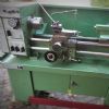
Denford Viceroy TDS 1/2 P.C.S.
| AJAX | 03/01/2021 23:54:08 |
| 433 forum posts 42 photos | I would like to remove the cross slide handle from the leadscrew which I assumed would be a simple task. I assumed it might be held with a pin or grub screw but on closer inspection I can see neither. However, the light and my eyes aren't great. I'm hoping there may be another Denford owner who can explain the process.
There is a "through hole" of some sort as demonstrated when I squirted WD40 straight through. The end looks like it may have been tapped with a hammer at some point, so maybe that is what is keeping it in place.
Does anyone have useful ideas for how I might go about improving the appearance and usability of the graduated dial when I can get it off? In a closely related question, I would be interested in experiences of machining a new plain / slotted cross slide for the purposes of attaching a vertical milling slide. I have access to a Bridgeport-sized milling machine at work but no surface grinder. |
| AJAX | 04/01/2021 00:01:55 |
| 433 forum posts 42 photos | I'm wondering if there is a taper pin there but as I can't actually see it I would have no idea which way the taper ran.
|
| Clive Foster | 04/01/2021 00:05:44 |
| 3630 forum posts 128 photos | Ajax The hole in the pin doesn't look very round. Suggests a roll pin has been fitted in place of a taper pin originally used to retain the handle. As I recall it the couple of instances I've seen were very similar in appearance. If that has been done you need to figure out the small end and drive the roll pin back out the correct way. It will leave a mess and will need re-reaming. I've found a soft wire brush is a good place to start on dials like yours. The small brass ones for Dremel and similar machines have worked well for me. Patience and a light touch. Clive |
| AJAX | 04/01/2021 06:53:01 |
| 433 forum posts 42 photos | Posted by Clive Foster on 04/01/2021 00:05:44:
Ajax The hole in the pin doesn't look very round. Suggests a roll pin has been fitted in place of a taper pin originally used to retain the handle. As I recall it the couple of instances I've seen were very similar in appearance. If that has been done you need to figure out the small end and drive the roll pin back out the correct way. It will leave a mess and will need re-reaming. I've found a soft wire brush is a good place to start on dials like yours. The small brass ones for Dremel and similar machines have worked well for me. Patience and a light touch. Clive Thanks for that, Clive. I agree with your suggestion that it could be a roll pin. I had a light tap previously believing the same but it did not budge. Perhaps it was in a tapered hole as you suggested and I was going the wrong way. Tricky to tell. I will take another look later today. Regards, Brian
|
| AJAX | 04/01/2021 17:42:15 |
| 433 forum posts 42 photos | I have found a working drawing for the top slide leadscrew. I have yet to check, but it looks like it may be the correct drawing. If it is, the leadscrew is drilled and reamed for 5/32" dia taper pins. I may be back later... |
| old mart | 04/01/2021 17:54:31 |
| 4655 forum posts 304 photos | Taper pins don't usually have holes in them, but roll pins always do. I would make a drift that was close to the hole diameter, and hold a heavy metal block with a 1/4" hole against it while tapping at the pin. Use a small hammer and gradually increase the power. A roll pin won't take much moving. |
| Pete. | 04/01/2021 17:58:35 |
 910 forum posts 303 photos | I wouldn't hit it with a hammer, if you have a cheap G clamp you could sacrifice, drill a hole in the fixed foot enough to let the roll pin enter it, put a pin punch in to the hole, put the G clamp on and squeeze the punch in to the hole, see if you can work out which side of the hole is bigger first. You might be able to see if the roll pin moves before drilling the G clamp, if it has a couple of mil before it reaches the outer edge. |
| AJAX | 04/01/2021 18:00:51 |
| 433 forum posts 42 photos | Thanks Old Mart and Pete. I will take a look later this evening. I'm working now and then the kids have to go to bed first... |
| Pete. | 04/01/2021 18:04:01 |
910 forum posts 303 photos | Just thought, put a small piece of tube on the fixed foot instead of drilling the clamp. |
| AJAX | 04/01/2021 23:56:30 |
| 433 forum posts 42 photos | Progress made. Two pins found and both tapped out with some encouragement. Neither were willing to press out with the (mostly unsuitable) tools I had available. The one closest to the end was drilled slightly off centre and the other one, well I can only speculate was drilled by a YTS trainee on his first day at work. Even though it's hidden, I will most likely be remaking that part!
|
| AJAX | 04/01/2021 23:59:27 |
| 433 forum posts 42 photos | I was actually surprised to find the needle roller bearings in place as I had planned to shim and/or add such bearings myself. The next job will probably be a complete strip down of the apron. I know the worm is very badly worn (I had it apart once before) and would like to get this replaced somehow. |
| Hopper | 05/01/2021 01:43:04 |
 7881 forum posts 397 photos | Posted by AJAX on 04/01/2021 23:56:30:
... The one closest to the end was drilled slightly off centre and the other one, well I can only speculate was drilled by a YTS trainee on his first day at work. Even though it's hidden, I will most likely be remaking that part!
Overkill. It looks like you have plenty of other work to go on with. Preserve that finest British craftsmanship as it is. It has worked just fine since the day it left the factory. (Maybe on a late Friday afternoon?) |
| not done it yet | 05/01/2021 08:00:53 |
| 7517 forum posts 20 photos | Are you sure the pin and collar, adjacent to the thrust bearing are correct? I might envisage a parallel pin located in the collar such that the collar would turn and alter the thrust adjustment as the thing wad assembled. Meaning that perhaps the collar should have slots at a slight angle, not a couple of apparently mis-drilled holes? |
| AJAX | 05/01/2021 09:05:21 |
| 433 forum posts 42 photos | Posted by not done it yet on 05/01/2021 08:00:53:
Are you sure the pin and collar, adjacent to the thrust bearing are correct? I might envisage a parallel pin located in the collar such that the collar would turn and alter the thrust adjustment as the thing wad assembled. Meaning that perhaps the collar should have slots at a slight angle, not a couple of apparently mis-drilled holes? That would make sense as it would allow for some adjustment. However, the collar is definitely mis-drilled on one side and exits as a single hole on the other. I would like to come up with a better solution to take up any slack when it is re-assembled. |
| Clive Foster | 05/01/2021 10:07:00 |
| 3630 forum posts 128 photos | That needle roller thrust bearing has the air of being a later addition rather than factory fit. Once you have the hole sorted its probably easiest to simply add shims behind the inner thrust washer to take up clearance. What it did with a similar sort of modification, albeit using dry bearing thrust washers rather than a needle roller to save space. Recess made a little too deep so the gap could be measured with a feeler gauge. Frankly if you have the makings and just decide to go for it its quicker to shim or make a second, longer, collar after measuring the gap with your first effort than it is to futz about arranging adjustment and setting up just so. I suspect the hole error occured when re-making the collar. Ultimate bodge on the mal-aligned hole is metal loaded filler. If worked in well a good brand is well up to that sort of job. Clive |
| AJAX | 05/01/2021 11:12:00 |
| 433 forum posts 42 photos | Posted by Clive Foster on 05/01/2021 10:07:00:
That needle roller thrust bearing has the air of being a later addition rather than factory fit. Once you have the hole sorted its probably easiest to simply add shims behind the inner thrust washer to take up clearance. What it did with a similar sort of modification, albeit using dry bearing thrust washers rather than a needle roller to save space. Recess made a little too deep so the gap could be measured with a feeler gauge. Frankly if you have the makings and just decide to go for it its quicker to shim or make a second, longer, collar after measuring the gap with your first effort than it is to futz about arranging adjustment and setting up just so. I suspect the hole error occured when re-making the collar. Ultimate bodge on the mal-aligned hole is metal loaded filler. If worked in well a good brand is well up to that sort of job. Clive Maybe you are right - it could be a later addition - who knows? Making a collar would be simple enough but it would be nice to add some form of adjustment or loading (spring?) or at least consider doing so instead of to shim. Some of the decision making may depend on how well I can clean that dial. If I can't make it readable then I'll have to buy or make a new one. |


Please login to post a reply.
Magazine Locator
Want the latest issue of Model Engineer or Model Engineers' Workshop? Use our magazine locator links to find your nearest stockist!
Sign up to our Newsletter
Sign up to our newsletter and get a free digital issue.
You can unsubscribe at anytime. View our privacy policy at www.mortons.co.uk/privacy
Latest Forum Posts
- *Oct 2023: FORUM MIGRATION TIMELINE*
05/10/2023 07:57:11 - Making ER11 collet chuck
05/10/2023 07:56:24 - What did you do today? 2023
05/10/2023 07:25:01 - Orrery
05/10/2023 06:00:41 - Wera hand-tools
05/10/2023 05:47:07 - New member
05/10/2023 04:40:11 - Problems with external pot on at1 vfd
05/10/2023 00:06:32 - Drain plug
04/10/2023 23:36:17 - digi phase converter for 10 machines.....
04/10/2023 23:13:48 - Winter Storage Of Locomotives
04/10/2023 21:02:11 - More Latest Posts...
- View All Topics
Support Our Partners


Shopping Partners
Subscription Offer

Latest "For Sale" Ads
- Reeves** - Rebuilt Royal Scot by Martin Evans
by John Broughton
£300.00 - BRITANNIA 5" GAUGE James Perrier
by Jon Seabright 1
£2,500.00 - Drill Grinder - for restoration
by Nigel Graham 2
£0.00 - WARCO WM18 MILLING MACHINE
by Alex Chudley
£1,200.00 - MYFORD SUPER 7 LATHE
by Alex Chudley
£2,000.00 - More "For Sale" Ads...
Latest "Wanted" Ads
- D1-3 backplate
by Michael Horley
Price Not Specified - fixed steady for a Colchester bantam mark1 800
by George Jervis
Price Not Specified - lbsc pansy
by JACK SIDEBOTHAM
Price Not Specified - Pratt Burnerd multifit chuck key.
by Tim Riome
Price Not Specified - BANDSAW BLADE WELDER
by HUGH
Price Not Specified - More "Wanted" Ads...
Get In Touch!
Do you want to contact the Model Engineer and Model Engineers' Workshop team?
You can contact us by phone, mail or email about the magazines including becoming a contributor, submitting reader's letters or making queries about articles. You can also get in touch about this website, advertising or other general issues.
Click THIS LINK for full contact details.
For subscription issues please see THIS LINK.
Digital Back Issues


Donate

 Register
 Log-in
Model Engineer Magazine
- Percival Marshall
- M.E. History
- LittleLEC
- M.E. Clock

ME Workshop
- An Adcock
- & Shipley
- Horizontal
- Mill

Subscribe Now
- Great savings
- Delivered to your door

Pre-order your copy!
- Delivered to your doorstep!
- Free UK delivery!
All Forum Topics > Manual machine tools > Removing lathe cross slide handle