Forum sponsored by:

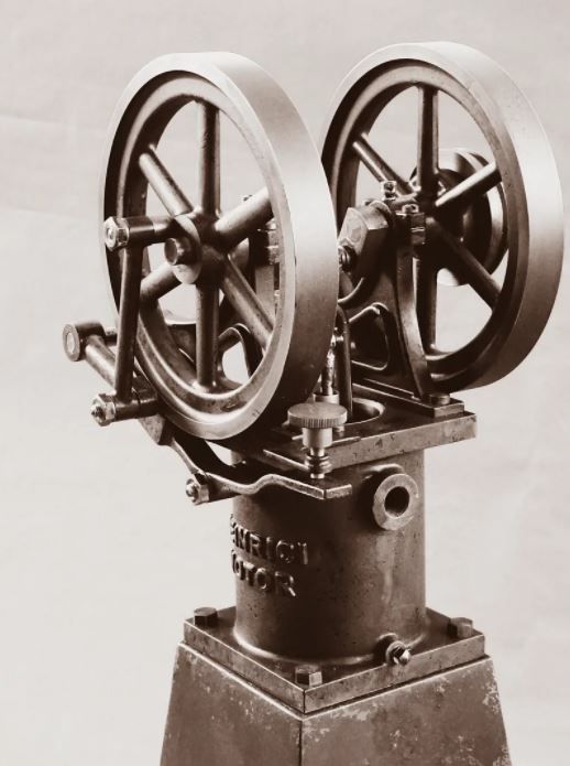
Heinrici without Castings
| JasonB | 08/12/2020 11:39:37 |
 25215 forum posts 3105 photos 1 articles | With Christmas fast approaching I've let Santa treat me early to a set of drawings for this engine and will be busy filling my stockings with barstock or possibly wood if I decide to make some patterns and get some of the flywheels cast but most likely will cut from a couple of discs of CI or steel. Edited By JasonB on 26/02/2021 13:46:44 |
| JasonB | 08/12/2020 11:44:42 |
25215 forum posts 3105 photos 1 articles | I've made a start on drawing this one up with a view to fabrication and cutting from solid rather than using the no longer available castings that the drawings are based on.
|
| Ron Laden | 08/12/2020 17:09:42 |
 2320 forum posts 452 photos | Hi Jason, You certainly have a way of finding interesting engines, another good project I think. Is this like the twin CHUKY in that it benefits from a larger bore i.e. will it be larger than 24mm.? Reading the link I thought it interesting that the crank sleeve bearings have the split clamp fitting for axial adjustment, I have not seen that before or is it quite common and used on other engines. Will look forward to following this one and the twin CHUKY of course. Ron
|
| JasonB | 08/12/2020 17:30:49 |
25215 forum posts 3105 photos 1 articles | I'm going to do this one the same size as the drawings which are for a 42mm bore engine, still quite small for Heinrici engines, this would be the second size up
|
| Steviegtr | 08/12/2020 17:33:22 |
 2668 forum posts 352 photos | That should keep you busy for a while. Steve. |
| John Olsen | 09/12/2020 21:56:04 |
| 1294 forum posts 108 photos 1 articles | I saw an engine just like those back in my early teens, somewhere in the early 60's. The guy who owned it had acquired it somehow and restored it, although he did not know what it was, and brought it around because my father was known around town as a steam man. Dad was not home, and I was intrigued because I could see it wasn't a steam engine, nor did it have a spark plug, so what could it be?? Not some sort of pump since there was no in or out. When Dad came he he of course recognised it immediately, found a suitable torch for heat and got it going. John |
| JasonB | 12/12/2020 19:17:18 |
25215 forum posts 3105 photos 1 articles | I've got a few more parts drawn out. One of the good things about barstock "castings" is that you can make them as true to the original as you want rather than have to slavishly follow what someone else has done where they may have left off details or altered things to make casting easier and/or cheaper.
|
| JasonB | 20/12/2020 20:16:23 |
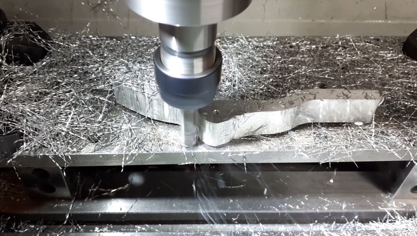
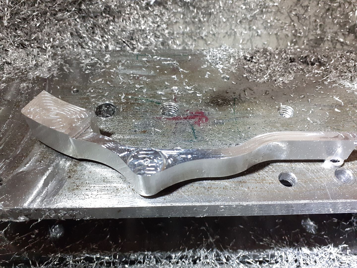
25215 forum posts 3105 photos 1 articles | Let the swarf making begin While waiting for some materials for the current engine under construction I thought I may as well get on with a couple of parts for the Heinrici as I had all the material in stock and the CNC had not been fired up for a couple of weeks so decided to do the levers that transfer the movement of the eccentric boss on the flywheel to the top of the pistons. To help with balance I went with 6082 Aluminium rather than have the weight of a heavier metal needing to be lifted along with that of the pistons. After drawing out in Alibre the exported files were opened up in F360 and the paths worked out. These were the first 3D parts since my old licence expired so I was limited in not having the "steep & Shallow" that I usually like to use but a combination of "scallop" for the upper curved surfaces and "ramp" for the steeper ones and vertical faces worked out quite well. I also did not have any rapids, not much of an issue with the two previously mentioned paths as the tool mainly stays down and in contact with the work, the Adaptive clearing probably took about 5mins longer than it would have with rapids enabled but that was not a problem. Hopefully all the info is in the video captions The finished items after a quick "shoe shine" with a strip of Emery Cloth. I've already sleeved the middle one and will do the same to the forked end as unlike other versions I'm not keen on running the pivots in bare aluminium
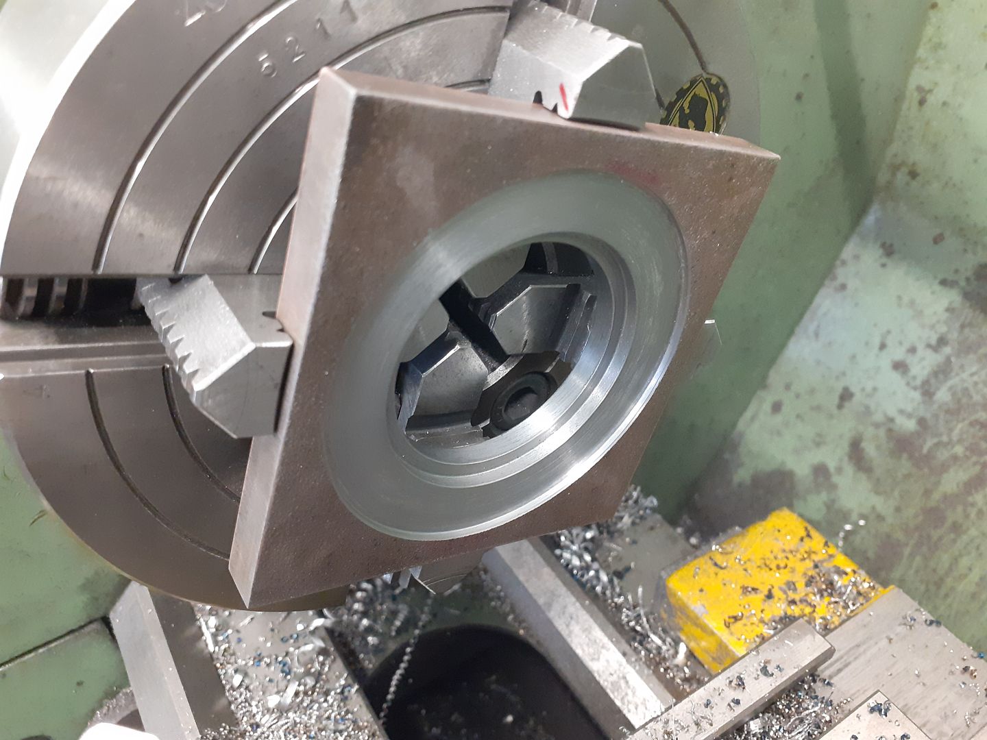
I have also made a start on some of the components that will become the fabricated water jacket, the tube is 3" ERW tube with the wall thinned down to 2.5mm by boring it out.
The 3 step pulley and brake adjusting knob were just straightforward turning jobs.
|
| Ron Laden | 21/12/2020 08:16:44 |
2320 forum posts 452 photos | Nice work Jason, it looks like the sleeves you have fitted are steel, obviously no need for them to be bronze or brass..? Ron |
| JasonB | 23/12/2020 16:30:31 |
25215 forum posts 3105 photos 1 articles | They are actually iron Ron, I had a couple of offcuts from some block that were the right sort of size so used them instead, original arms were iron castings.
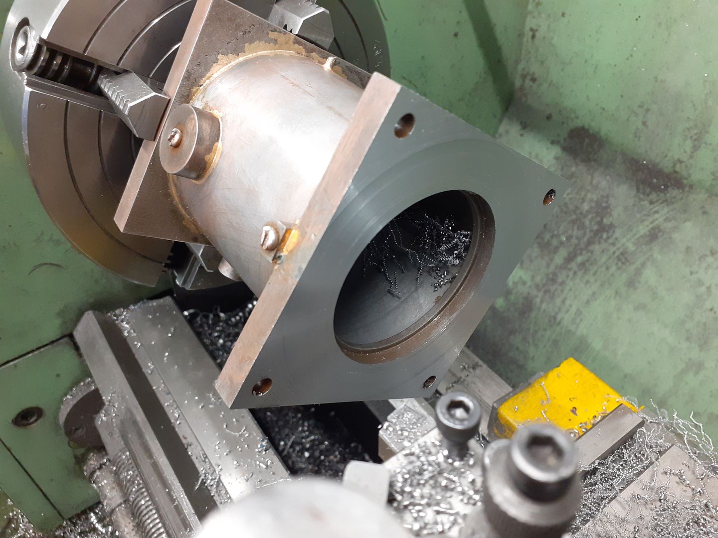
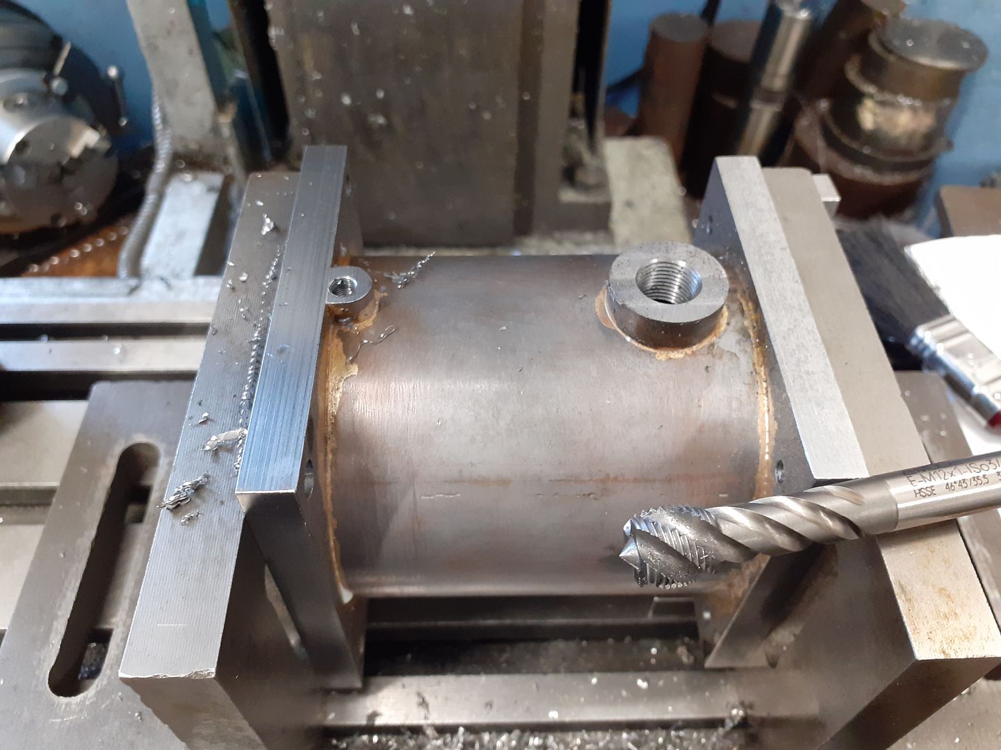
A bit of manual machining this weekend starting with the end plates that will form the top and bottom of the water jacket. After pickling the 10mm black bar was bored out as I felt this would be easier now than 100mm down inside the jacket plus it reduced the bulk of metal needed to be heated for soldering.
After soldering and another dunking in the pickle the jacket was brought down to overall length having allowed 0.5mm either end for a clean up pass.
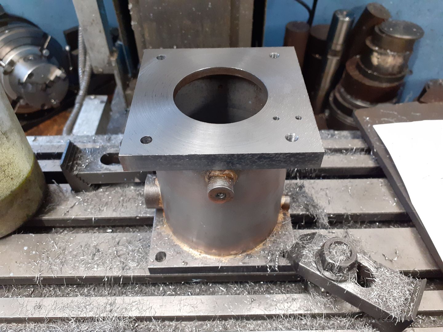
Then onto the mill to trim around the top flange which I had left 1mm all round should it not line up perfectly with the bottom after soldering. Also drilled and tapped various holes for the main bearing brackets and brake adjuster bracket.
Then with it held between a pair of angle plates worked my way round milling the bosses back to length then drilling and tapping as required.
|
| Ron Laden | 24/12/2020 13:37:37 |
2320 forum posts 452 photos | Looking good Jason, you mention pickling the black steel, would you mind explaining that as I am not familiar with it having never worked with any black steel. What solution do you use and I assume that you cant just machine off the scale, is it similar to the chilled areas on cast iron..?. Ron |
| JasonB | 24/12/2020 16:59:09 |
25215 forum posts 3105 photos 1 articles | The black mill scale can be a bit abrasive so even if milling it off you will get more cutter wear than if it were bright bar so the pickle removes it without affecting tools. I use Feb "Brickclean" which is basically a 10 %hydrochloric acid and after about 1/2hr the scale just falls off. Use it outside, rinse well after use, dry part and give a quick spray of WD40 to stop it rusting. Also don't forget you have something in the pickle as it can start to eat into it if left for several hours. Have a look at John Stevenson's couple of posts on this page Edited By JasonB on 24/12/2020 17:15:23 |
| Ron Laden | 25/12/2020 09:37:34 |
2320 forum posts 452 photos | Thank you Jason and a happy Christmas to you. Ron |
| JasonB | 27/12/2020 19:02:41 |
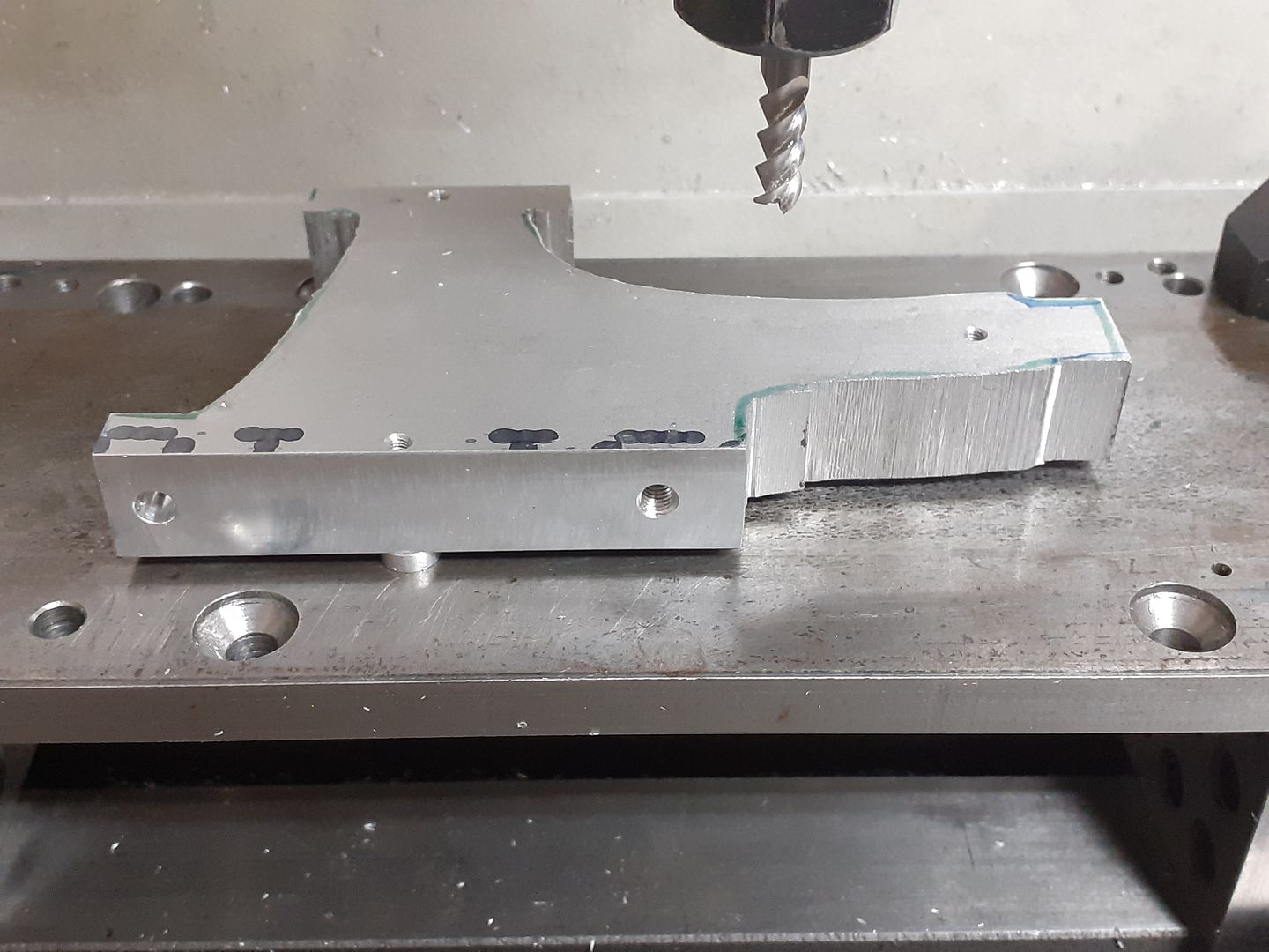
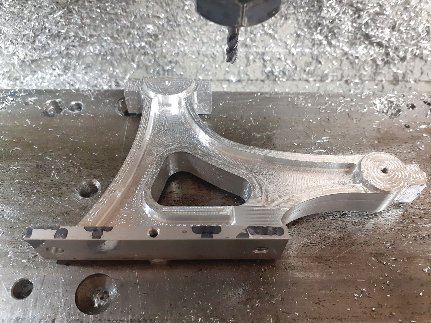
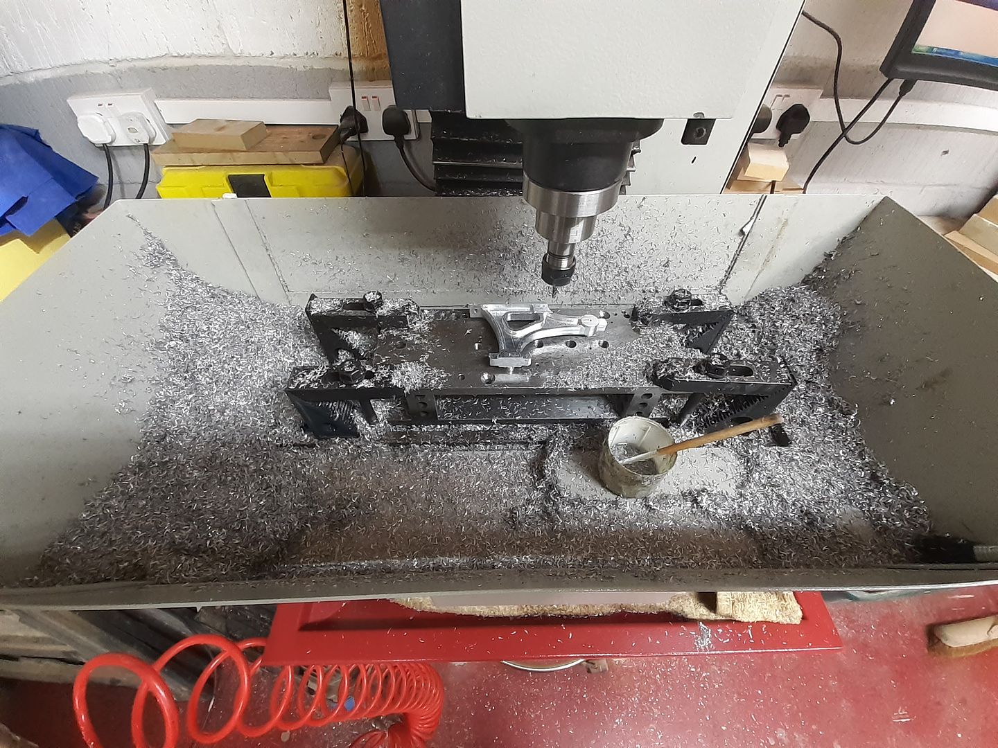
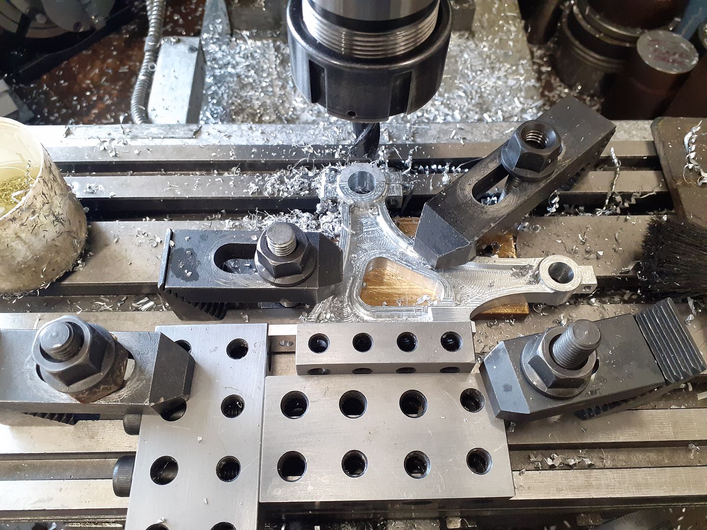
25215 forum posts 3105 photos 1 articles | Back to a bit more swarf production on the CNC today. The two brackets that support the crankshaft and rocker shaft were exported to F360 and the various adaptive roughing and finishing paths worked out for both sides. Rather than waste too much metal I printed out two profiles and laid these on some 16mm thick 6082 plate and nested then as close as possible then cut them out on the vertical bandsaw. The bottom and end of the foot were machined on the manual mill to give me a reference corner and the mounting holes added at the same time. I then drilled and tapped three M3 holes to be used to holed the part to my well used machining plate, the plate was setup and then drilled on the CNC so easy to line things up. 6mm 3-Flute carbide cutter uncoated and with a helix angle to suit aluminium loaded up and here it is ready to go.
This shot is at the end of the first 5mm high stepdown of the adaptive, the 5000rpm and 500mm/min feed producing decent chips without stressing the machine and within what I could blow/brush away manually.
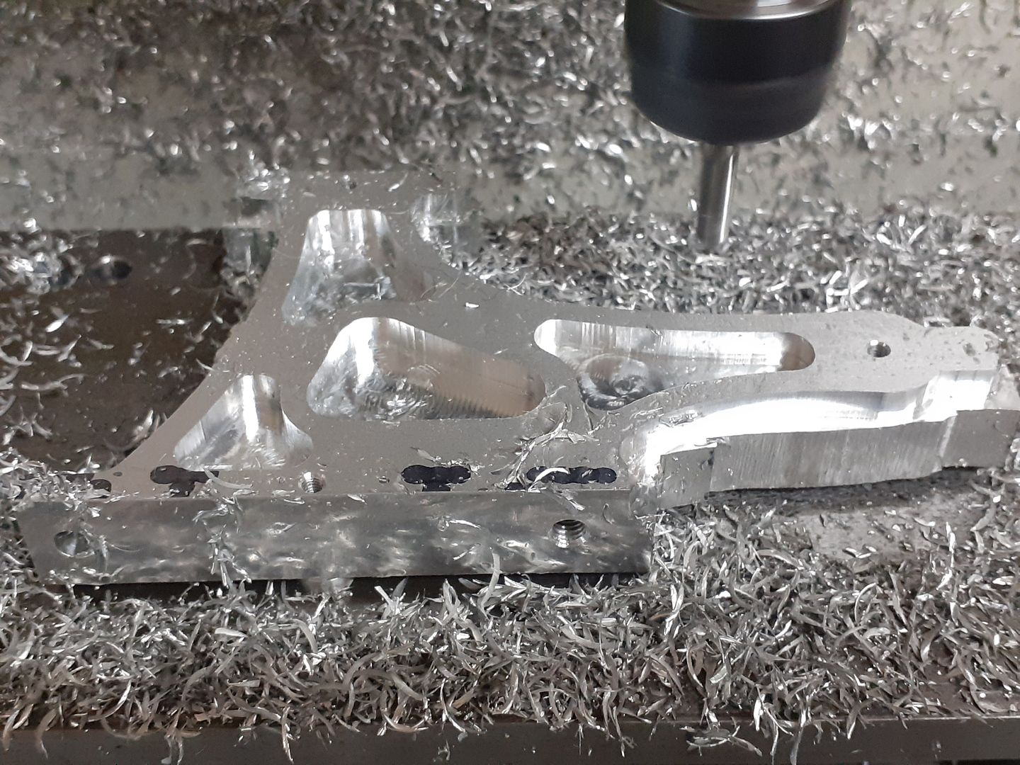
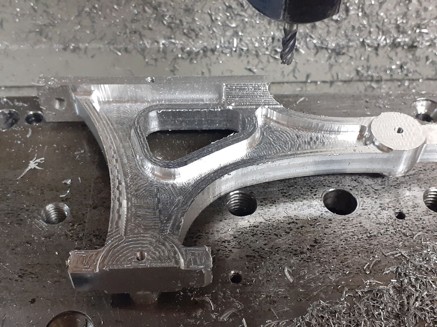
This is at the end of the adaptive (roughing) which was set to leave 0.5mm to be removed by the finishing cuts.
I then changed to a 4-flute 4mm dia cutter with 1mm radius corner (convex) to do the rest of the work.
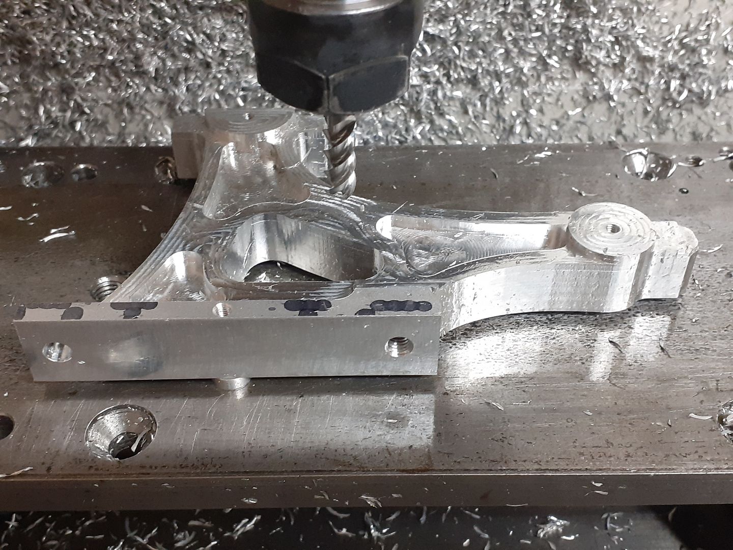
The second side was done in much the same way but with the tool not going around the outside of the work as that had been cut to full depth on the first setting.
I tend to judge how productive the day has been by the amount of swarf produced, F360 tells me that had I started with rectangular blocks then 84% would have been turned to swarf, as I nested them it was probably in the region of 65-70%. Some of the waste lumps will be used to make the caps from.
Once the caps have been made tomorrow I will bore the two shaft holes before softening all the edges and surfaces to get things looking a little more "cast" |
| JasonB | 28/12/2020 19:00:09 |
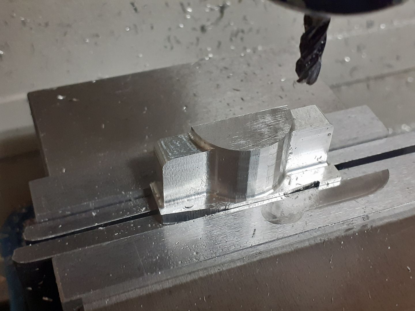
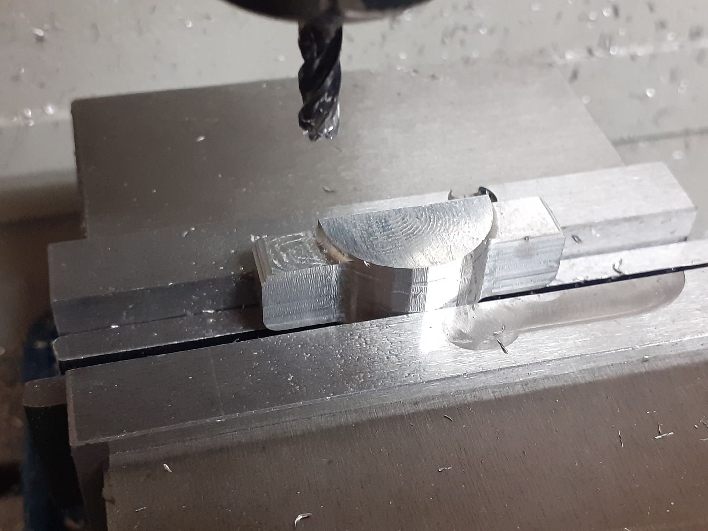
25215 forum posts 3105 photos 1 articles | So a couple of off cuts of the 16mm aluminium plate were put in the vice and milled to shape with a 4mm cutter with the 1mm corner radius so they matched the brackets.
Then mounted the other way up the holding piece was milled away before reducing the two clamp lugs to height
After drilling and tapping a few holes the caps were screwed into place and the holes for the crankshaft bearings and rocker shaft reamed. I used a couple of metric 20-40-80 blocks to provide a stop so that the second bracket could be slipped into the same position.
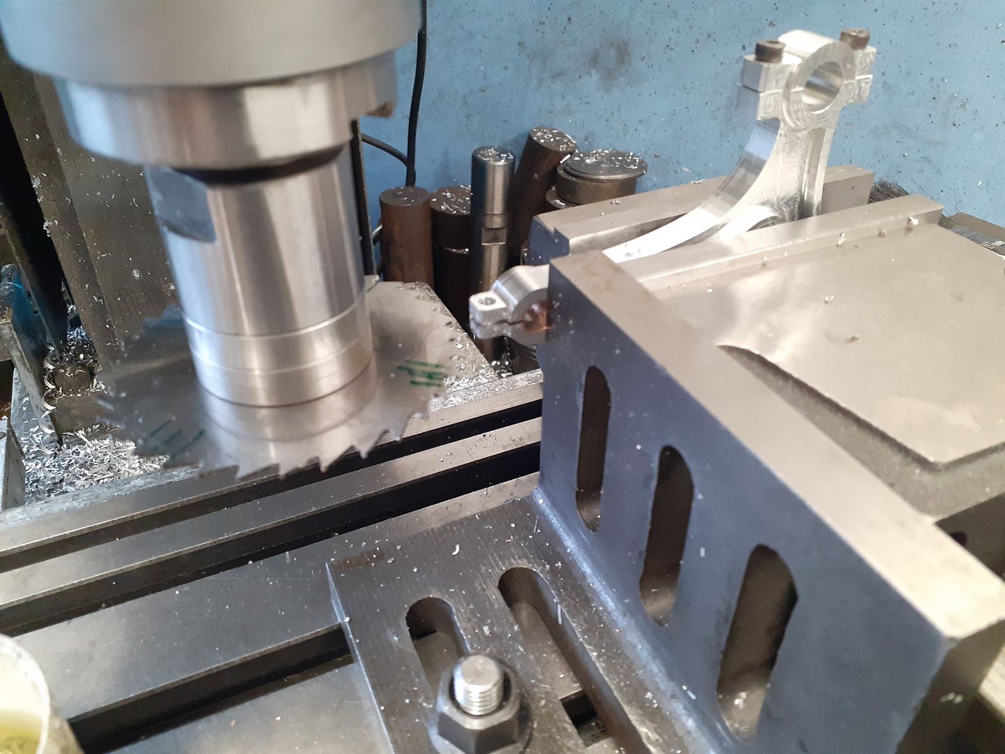
After Loctiting a bronze bush into the rocker shaft holes these were split with a 1mm wide slitting saw. The angle plate pressed up against the side of the bracket stops any tendency for it to flex as I'm gripping it my the bottom flange which is quite a way from the cut.
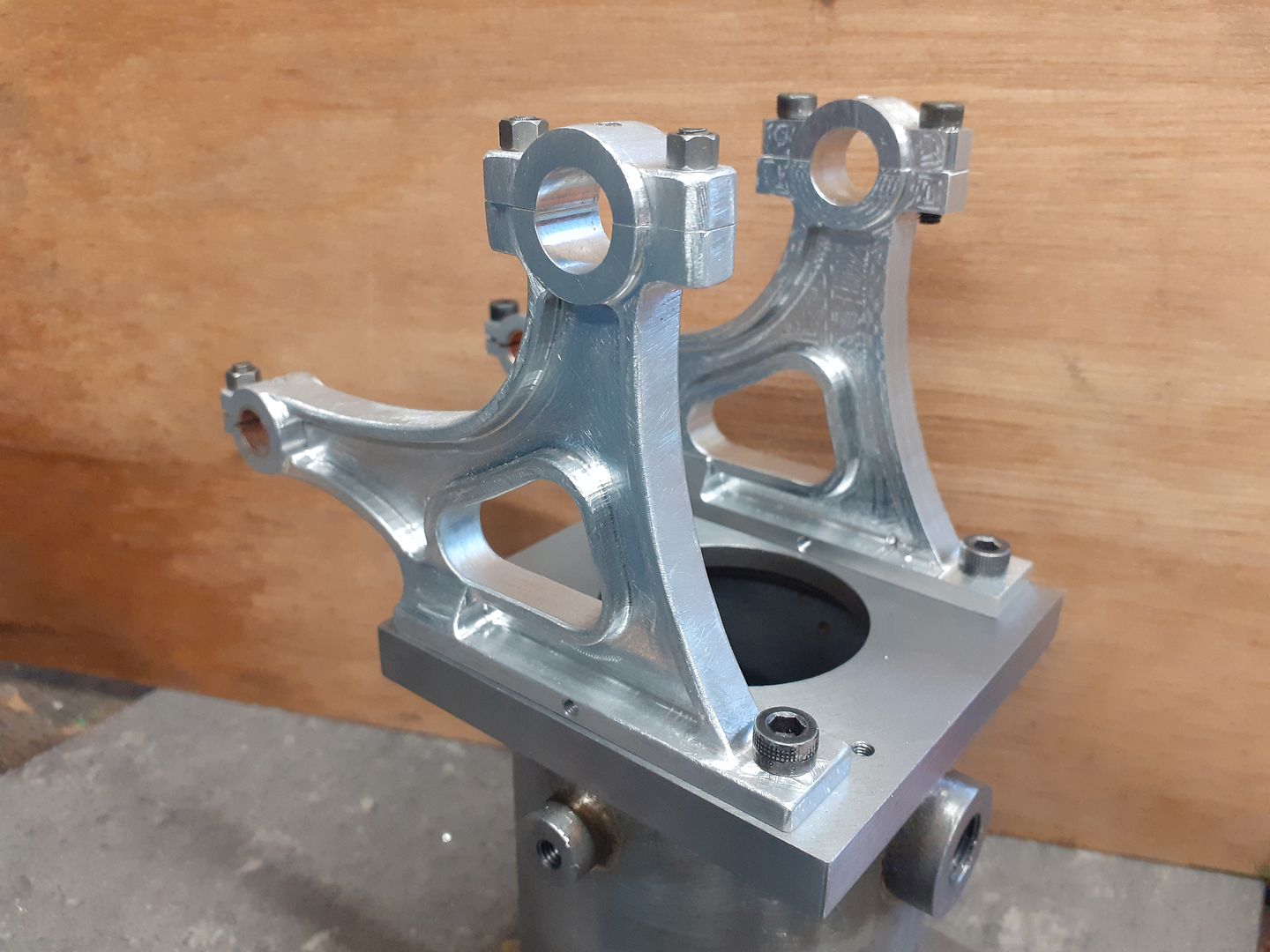
First of the brackets has had a start made of knocking off the corners and generally softening up the machined look so it more closely resembles a casting yet not incorporating some of the undesirable traits of certain castings.
|
| Ron Laden | 29/12/2020 08:59:14 |
2320 forum posts 452 photos | That looks a treat Jason, very nice work the brackets certainly have a cast look about them. Edited By Ron Laden on 29/12/2020 08:59:42 |
| JasonB | 01/01/2021 16:49:16 |
25215 forum posts 3105 photos 1 articles | The speed of the Heinrici engines could be controlled by the use of a friction brake on one of the flywheel rims so while the aluminium swarf was flying I thought I may as well make that from another piece of the 16mm thick 6082. This action shot is it part way through profiling the outside using a 10mm dia 2-flute cutter for aluminium at 5000rpm, full 16mm high x 0.5mm deep cut, I started with a feed of 300mm/min but as the job got thinner had to reduce that down to about 60%.
Then a change to a 10mm 4-flute cutter with 1mm corner radius to take it down to the various heights.
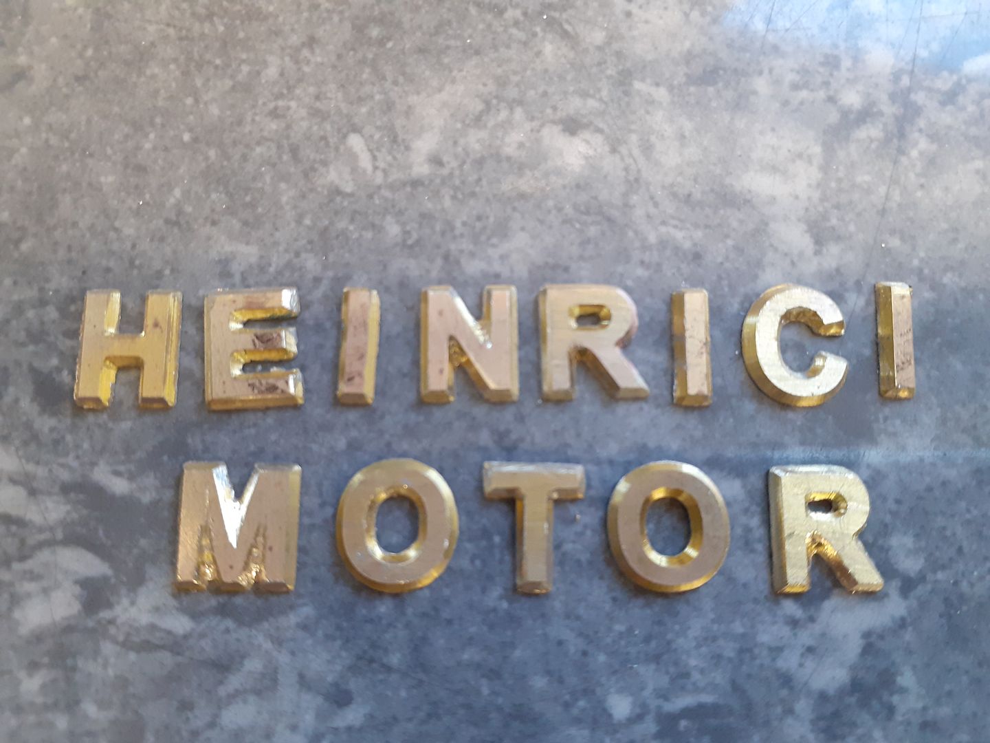
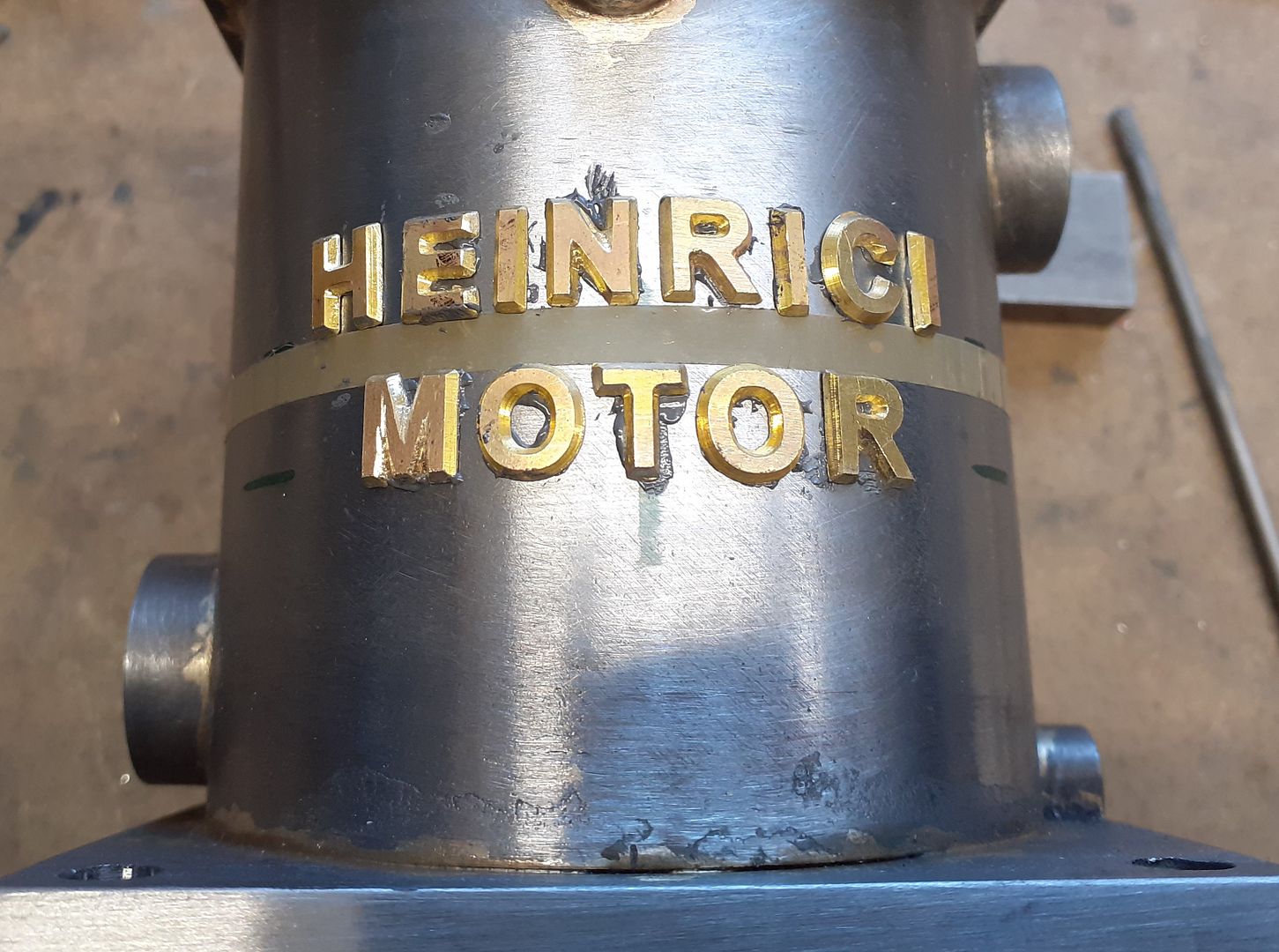
Looking at the available casting sets none seem to have the writing cast onto the side of the water jacket so I thought this would be a nice feature to add and if you are going to spend the time making a model then might as well get it as true as possible. I posted about cutting the letters yesterday in the KX3 thread and this is them after an initial clean up.
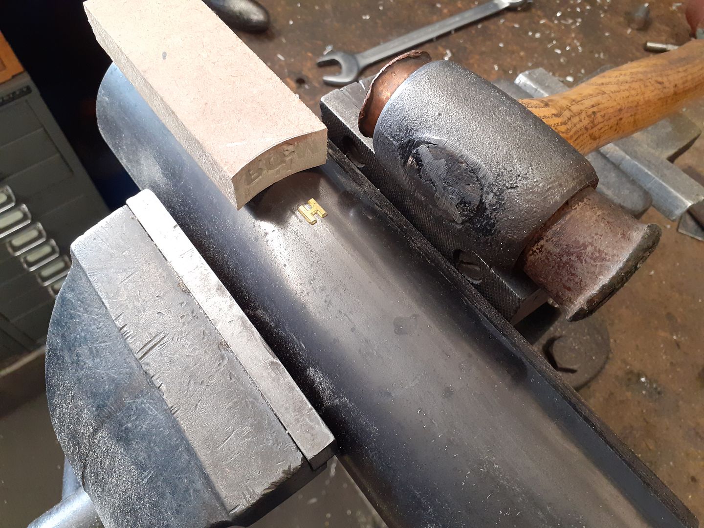
The reason for cutting them from soft bending brass was so that each letter could be bent to the curve of the jacket which was done by simply sawing a concave face into a scrap of MDF which was used as a punch onto the letter as they sat on some of the tube used for the jacket.
A piece of narrow sign writers masking tape was used to get a horizontal line and the letters spaced by eye starting from the ctr line positions taken from the Alibre file and stuck on with JB Weld. I let it sit for just over an hour after taking this photo so that it thickened up a bit then set the final positions.
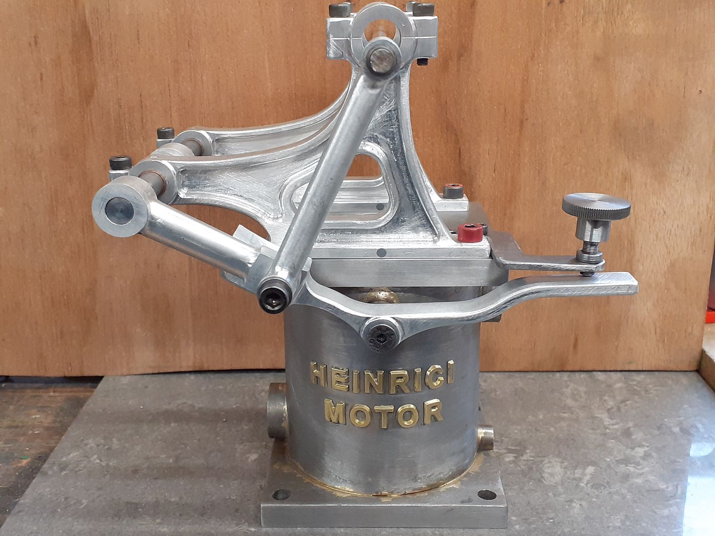
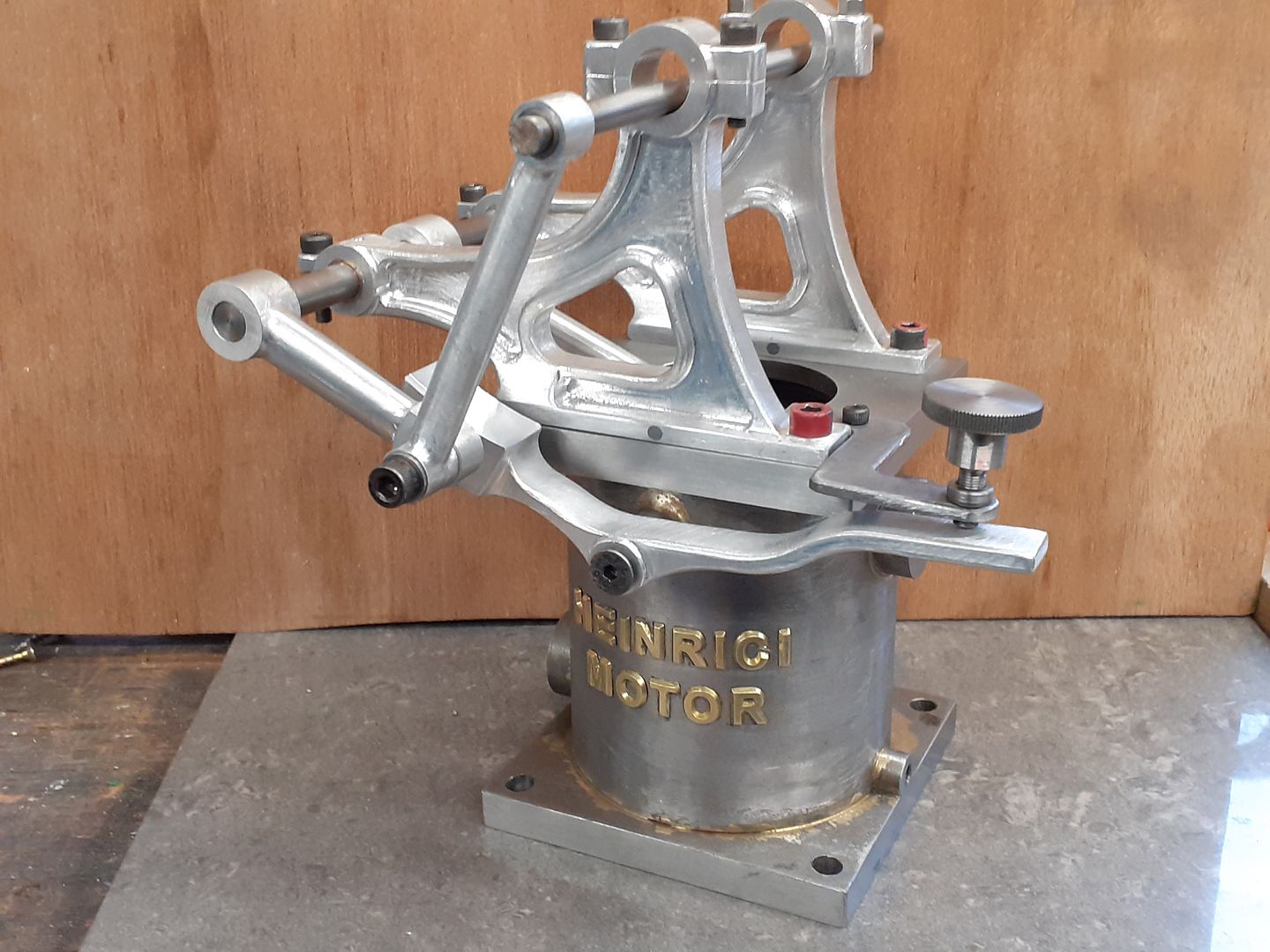
After a bit of a clean up I'm happy with how they turned out, will give them a couple of coats of high build primer filler and knock the edges back a bit more at a later date. Starting to look a bit more like a Heinrici now.
|
| Ron Laden | 04/01/2021 07:42:11 |
2320 forum posts 452 photos | Lettering looks great Jason. Are you going to leave the lettering painted or cut back the face to reveal the brass, I think it would stand out and look good but you may not of course. Ron |
| JasonB | 04/01/2021 10:09:10 |
25215 forum posts 3105 photos 1 articles | I just used brass as it's easy to cut and bend, the originals were just part of the cast iron jacket and painted so that's what I'll go with. |
| PatJ | 11/01/2021 08:16:59 |
 613 forum posts 817 photos | Another great looking engine. I need to go faster. I am getting hopelessly behind.
. |


 I've not seen many engines with the claim the design is to help line things up and not sure it was actually a feature of the full size as a lot seem to show a separate cap.

.jpg)
.jpg)
.jpg)
Please login to post a reply.
Magazine Locator
Want the latest issue of Model Engineer or Model Engineers' Workshop? Use our magazine locator links to find your nearest stockist!
Sign up to our Newsletter
Sign up to our newsletter and get a free digital issue.
You can unsubscribe at anytime. View our privacy policy at www.mortons.co.uk/privacy
Latest Forum Posts
- *Oct 2023: FORUM MIGRATION TIMELINE*
05/10/2023 07:57:11 - Making ER11 collet chuck
05/10/2023 07:56:24 - What did you do today? 2023
05/10/2023 07:25:01 - Orrery
05/10/2023 06:00:41 - Wera hand-tools
05/10/2023 05:47:07 - New member
05/10/2023 04:40:11 - Problems with external pot on at1 vfd
05/10/2023 00:06:32 - Drain plug
04/10/2023 23:36:17 - digi phase converter for 10 machines.....
04/10/2023 23:13:48 - Winter Storage Of Locomotives
04/10/2023 21:02:11 - More Latest Posts...
- View All Topics
Support Our Partners


Shopping Partners
Subscription Offer

Latest "For Sale" Ads
- Reeves** - Rebuilt Royal Scot by Martin Evans
by John Broughton
£300.00 - BRITANNIA 5" GAUGE James Perrier
by Jon Seabright 1
£2,500.00 - Drill Grinder - for restoration
by Nigel Graham 2
£0.00 - WARCO WM18 MILLING MACHINE
by Alex Chudley
£1,200.00 - MYFORD SUPER 7 LATHE
by Alex Chudley
£2,000.00 - More "For Sale" Ads...
Latest "Wanted" Ads
- D1-3 backplate
by Michael Horley
Price Not Specified - fixed steady for a Colchester bantam mark1 800
by George Jervis
Price Not Specified - lbsc pansy
by JACK SIDEBOTHAM
Price Not Specified - Pratt Burnerd multifit chuck key.
by Tim Riome
Price Not Specified - BANDSAW BLADE WELDER
by HUGH
Price Not Specified - More "Wanted" Ads...
Get In Touch!
Do you want to contact the Model Engineer and Model Engineers' Workshop team?
You can contact us by phone, mail or email about the magazines including becoming a contributor, submitting reader's letters or making queries about articles. You can also get in touch about this website, advertising or other general issues.
Click THIS LINK for full contact details.
For subscription issues please see THIS LINK.
Digital Back Issues


Donate

 Register
 Log-in
Model Engineer Magazine
- Percival Marshall
- M.E. History
- LittleLEC
- M.E. Clock

ME Workshop
- An Adcock
- & Shipley
- Horizontal
- Mill

Subscribe Now
- Great savings
- Delivered to your door

Pre-order your copy!
- Delivered to your doorstep!
- Free UK delivery!
All Forum Topics > Miscellaneous models > Heinrici without Castings