Forum sponsored by:

CHUK V From Concept to Castings & Beyond
| JasonB | 20/11/2020 20:09:24 |
 25215 forum posts 3105 photos 1 articles | Regular forum followers may have seen me mention that I was working on something but could not reveal more detail at the time. However I can now say that I have been collaborating with Graham Corry of Alyn Foundry an a new engine to extend his existing "CHUK" range From Graham: "CHUK " V "
|
| JasonB | 20/11/2020 20:15:54 |
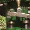
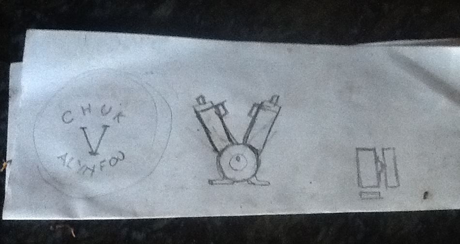
25215 forum posts 3105 photos 1 articles | At the end of August Graham sent me that napkin sketch with a very basic spec, I liked the idea and asked him for a few dimensions of the cylinder castings and while waiting had come up with a basic design using enlarged 3D models of many of the parts from my version of the CHUK range CHUKY which was covered here
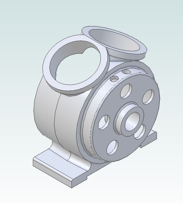
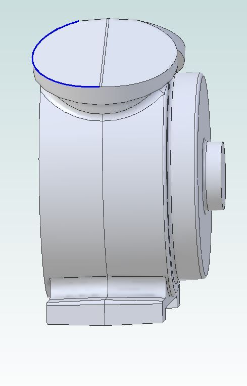
After several exchanges of e-mails sending screen shots of the evolving engine to Graham for comment a final design had been agreed by the end of September with a one piece crankcase that would carry the overhung crank on one side and have a cover plate on the other side bearing the CHUK V name with the intention that this could be buffed up to look like the Stuart BB that Graham had seen. It will use a modified version of the existing cam profile that will be housed within the crankcase with tapped guides set into the top of the crankcase. The builder will have the option to machine 5 holes in the flywheel side of the casting to make it possible to watch what is going on inside.
As Graham mentioned the existing cylinder castings can be used with some machining of the end to allow them to be fixed to the crankcase flanges with yes you guessed it 5 studs and nuts. The head castings will incorporate a boss to house the exhaust spring and may be retained with studs and nuts or with counterbored holes for screws
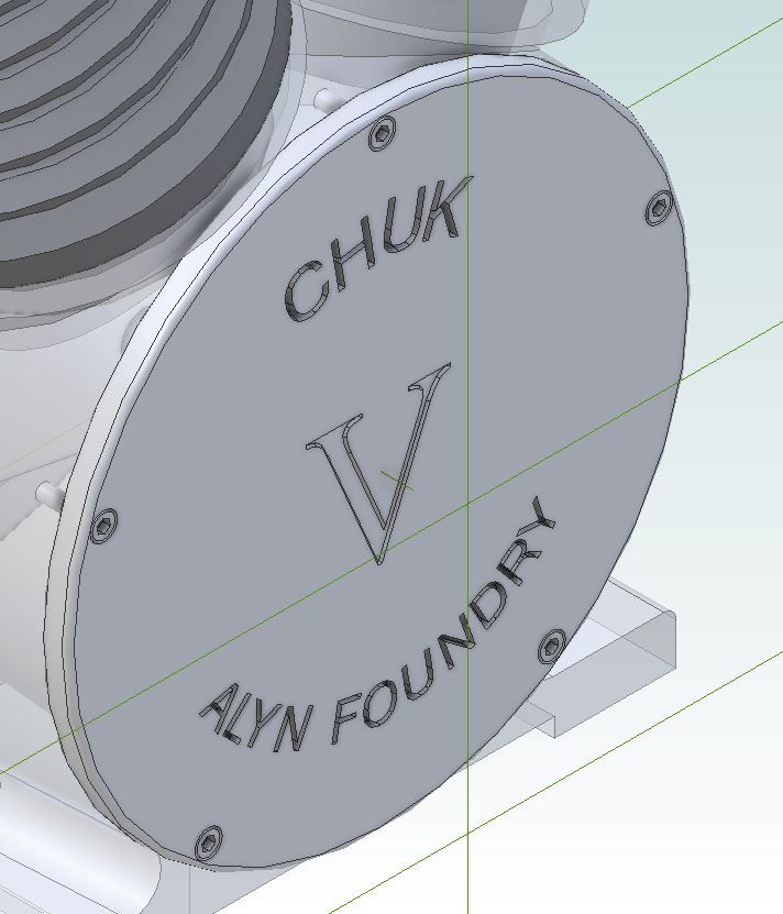
The plate that closes up the crankcase will have recessed letters allowing the builder to buff up the surface and inlay the writing with their chosen colour of paint, red or black seem likely candidates. Once again the cover will have 5 fixings and Graham likes the idea of the recessed screws.
For those that want to make their engine look more like a motorcycle Vee Twin I also sketched up a version with modified heads and exhaust pipes
|
| JasonB | 21/11/2020 20:00:35 |
25215 forum posts 3105 photos 1 articles | Now that I had the engine drawn out it was time to start converting the drawings to ones that could be used as patterns. Starting with the crankcase I made a copy of the file shown in my post above and then suppressed all the features that I did not need such as bearing hole, holes in the flanges for the cylinders to locate in, etc. I then added machining allowances where needed as well as draft angle so that the patterns could be pulled from the sand.
I decided it would be easiest to start by cutting two matching "halves" and then add the endplate with bearing boss as a third part so did a simple "extrude - cut" which left me with half a crankcase. I find that sometimes Alibre can have problems adding fillets to some internal corners once you start having more complex shapes joining at odd angles so left most of the fillets off the pattern file but will make use of the shape of the cutter to include them on the actual pattern.
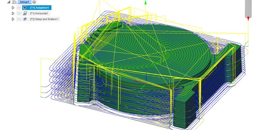
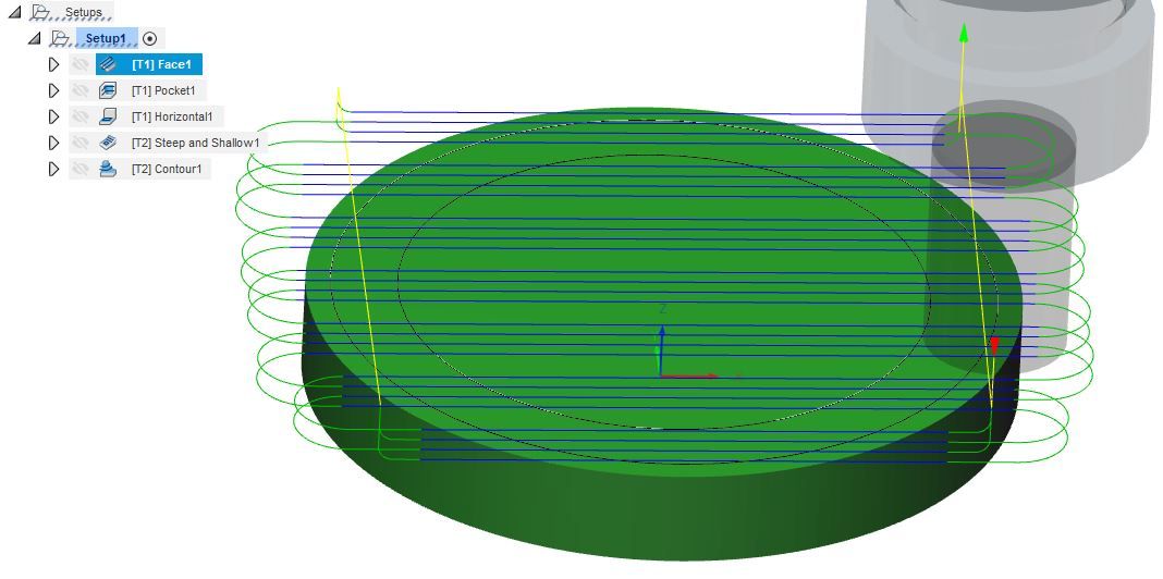
The file was then exported to Fusion 360 to do the CAM, I ended up with 3 separate strategies to produce the shape. Firstly an adaptive clearing one which is basically a roughing out pass leaving 0.5mm stock which was done with a long shank 4-flute carbide cutter at 5000rpm with a feed of 450mm/min taking most of the material off with a 5mm high by 1mm deep cut then just stepping up 1mm for the fine roughing which can better be seen on the next but one photo. The blue lines are the path that the centre of the end of the tool follows when cutting the yellow are where it is moving between cuts
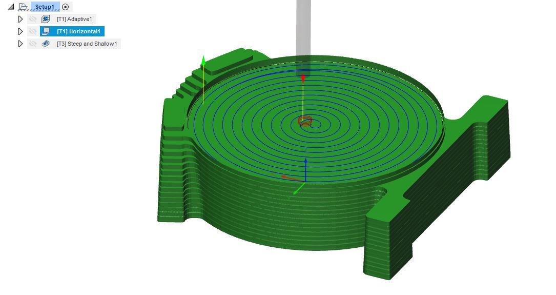
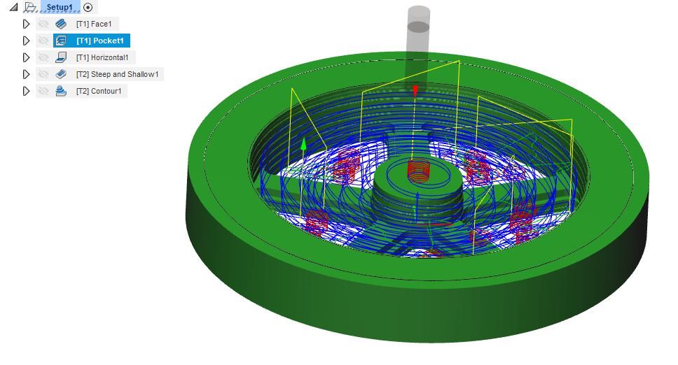
Next using the same tool and speeds but with a 4mm stepover the flat face had the final 0.5mm removed. you can see the stepped finish that the adaptive cuts left better in this photo as the tool paths don't get in the way.
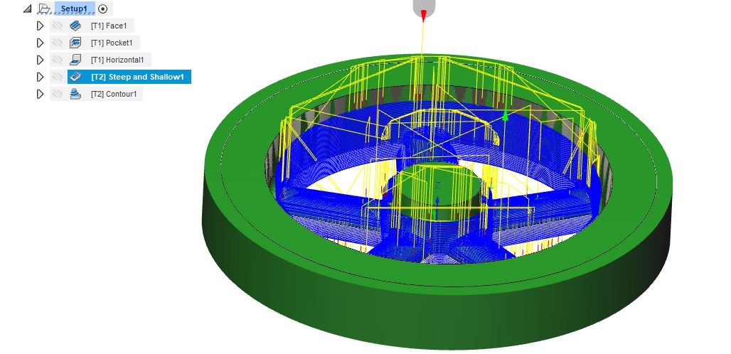
Finally a long shank 4-flute 6mm carbide ball nose cutter was used with a "steep and shallow" strategy that was set with a fine 0.33mm stepover or "scallop" between cuts again running at my max speed of 5000rpm but feeding a bit faster at 550mm/min
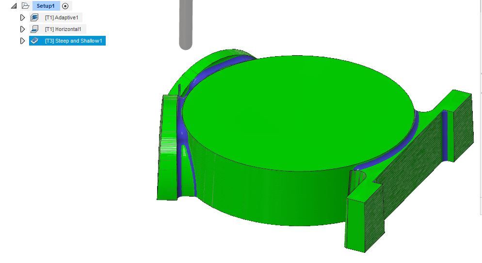
This image shows how F360's simulator will leave the finished part, the bright green areas are where it has cut to the drawn surface, the blue is material it has not removed which you can see is basically all the places where I wanted an internal fillet. This method works well on the easily cut wood but you do have to watch when doing it on metal as the percentage tool engagement can go up a lot and chatter is possible, in these cases it is better to try and draw in the fillets with a radius say 10% more than the radius left by the tool.
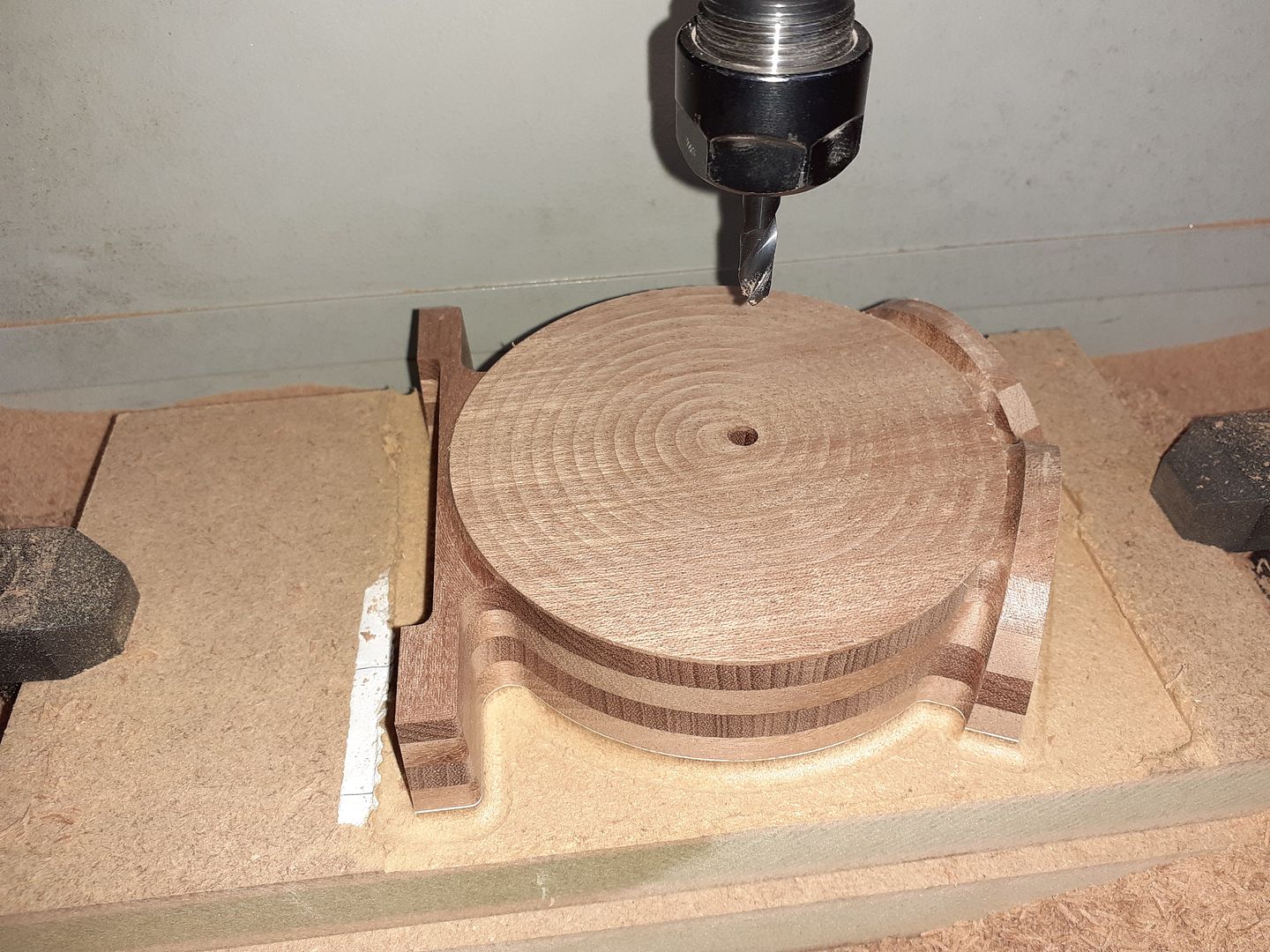
A couple of mouse clicks and the thousands of lines of G-code that F360 created were on a memory stick that could be transferred to the mill. It was now time to cut some brown stuff, however I was wary that the flanges and particularly the feet could be broken off easily if the grain was not in the right direction. So rather than cut from a solid block of timber I laminated some thin boards of Sapele together which would have a similar effect to using plywood with it's grain that runs in two directions. I glued my blank to a piece of MDF with Titebond placing a sheet of copy paper in the joint which makes it easy to separate afterwards. Sorry No video of the crankcase being machined but this is after the final cuts with the ball nose tool and I also added a 6mm hole for later alignment.
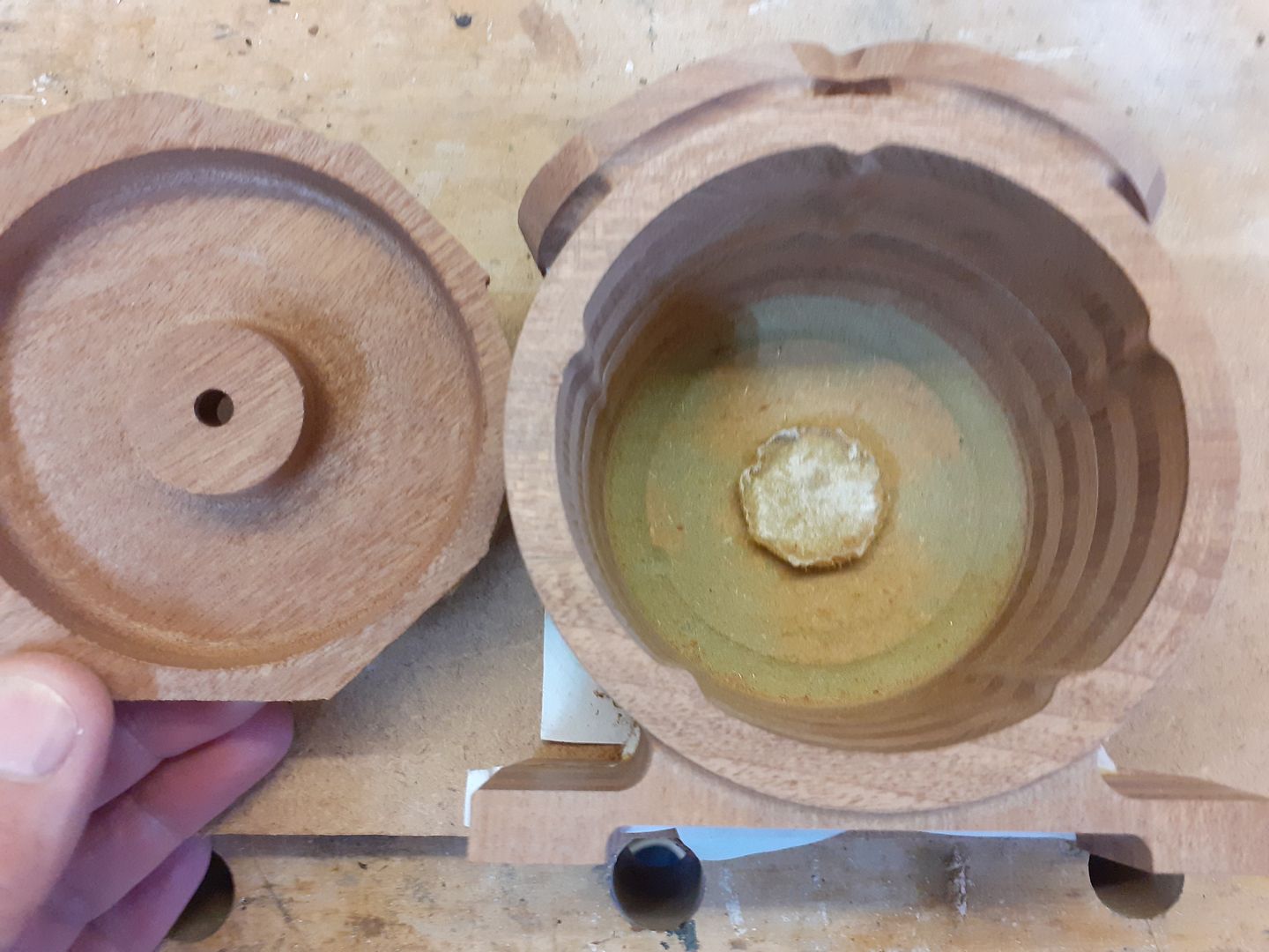
Early on Graham had suggested that the crankcase could be cast without the need for a core which would save me time having to make a core box and also keep casting costs from the foundry lower. By having the external draft angles going each way from the split line but the internal angle being constant through both haves from the open side of the crankcase this is possible. So the next thing to do was glue the outer face of one half to another MDF clamping board and then glue the two mating faces of the pattern together both again with the sheet of paper. The inner cavity could then be roughed out with a long shank 10mm cutter and finished with a long shank 10mm ball nose cutter working it's way around the inside in a steadily lowering spiral. I also used the same cutter to form the inside profile of the end plate.
After separating the case from the clamping board and shaping the outside of the end plate the two were glued together and a fillet of filler added and sanded smooth. The actual surface of the wood needed hardly any sanding at all and came out far smoother than any of the hobby 3D printers would have done.
|
| Colin Heseltine | 21/11/2020 21:10:33 |
| 744 forum posts 375 photos | Jason, That is fantastic work. Its interesting to see the various stages you have to go to to end up with a pattern. I guess at some time in the future this may have to get added to my casting pile. Colin
|
| JasonB | 22/11/2020 10:14:07 |
25215 forum posts 3105 photos 1 articles | Stages were slightlt different to the traditional way where the main body would likely have been turned then turned flanges and the feet added on before blending it all with fillets but it seems to have come out OK and the photos I have seen of the castings look good. I'm not sure if Graham will be making them available, if so it will probably just be a small batch for those interested so get your name on the list. At the moment there are just two sets of castings, one each for Graham and myself plus a few extra flywheels as they are a useful size for my 24mm bore engines. |
| Ron Laden | 23/11/2020 10:24:28 |
 2320 forum posts 452 photos | Great work Jason, unless I have missed it what size is the engine..? Ron |
| Michael Gilligan | 23/11/2020 10:31:59 |
 23121 forum posts 1360 photos | Posted by Colin Heseltine on 21/11/2020 21:10:33:
Jason, That is fantastic work. Its interesting to see the various stages you have to go to to end up with a pattern. […] . Agreed !! Please keep it coming, Jason MichaelG. |
| Alyn Foundry | 23/11/2020 11:43:37 |
 10 forum posts 6 photos | Good morning All. I would like to thank Jason publicly for turning a thought into a reality. CHUK was conceived for entry level machinists/modellers around 20 years ago when I was working for Chester UK. It's design is loosely based around the Victorian/Edwardian Vacuum engine toys made by Ernst Planck. CHUK 1 was a vertical, CHUK 2 an inverted vertical and CHUK 3 a horizontal. It's bore diameter can range from 30 mm to a maximum of 48 mm. The stroke is 50 mm. Up until CHUK " V " all engine kits were produced in Cast Iron with additional cast Brass embellishments. Here's a link to a recent video of CHUK 3 MK 2 with the new style rotary valve and " Chipmaster " exhaust. https://youtu.be/CyouJxF6dpI Cheers Graham. |
| JasonB | 23/11/2020 19:39:47 |
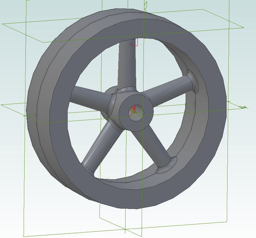
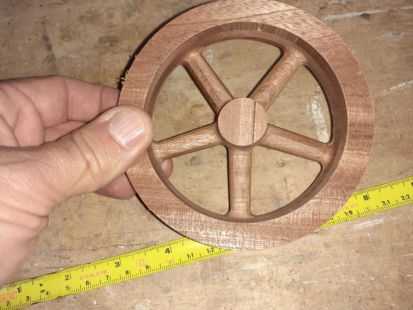
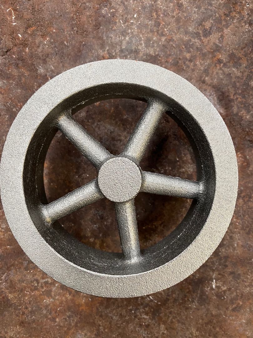
25215 forum posts 3105 photos 1 articles | Ron as well as the sizes Graham has given the whole crankcase would take up a block 135 x 115 x 65mm, completed engine will stand approx 240mm high x 210mm wide at the top of the heads. Thanks for the interest Michael, I was going to do a shorter post for the flywheel but have done it in a similar fashion to the crankcase plus a video. Needless to say the flywheel was always going to have 5 spokes right from the start although it was chopped and changed quite a few times, originally I thought that it would need something about 7" dia due to there being two cylinders which meant it would extend below the crankcase but Graham felt a smaller one would do so we settled on a of about 120mm dia with a wide rim and tapering oval section spokes. Like the crankcase the 3D model was enlarged to allow for shrinkage, draft angles and machining allowance added and a model of the half pattern exported to F360
First operation was to face the stock taking it down to the finished height of the edge of the rim. I've put the all the cutter details on the video so won't repeat them again here.
The bulk of the waste material was removed with a pocketing path leaving 0.5mm for finish cuts. While the 6mm tool was in the collet a finish cut was taken to bring the hub to height. As well as the blue and yellow paths mentioned in the last post there are some red ones which are where the tool ramps down into the work in a spiral which is kinder to the cutter than just plunging straight down.
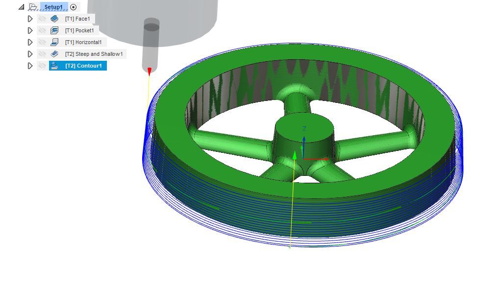
Changing to a ball nose cutter the inside was finished with a "steep and shallow" path
Finally the tapered outer edge was finished with a "ramp" cut which has the tool gradually dropping down as it follows the profile, in this case I had it drop 0.75mm over one rotation which was approx 400mm length of cut.
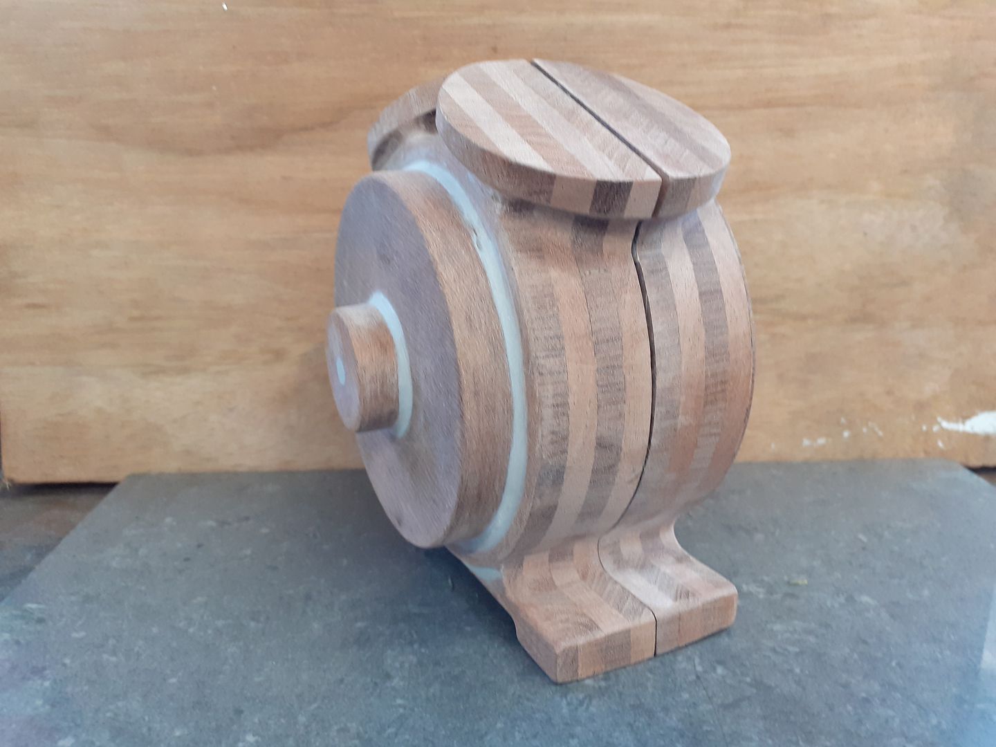
I'm pleased with how it turned out, there was a bit of splintering of the top edge that can be seen on the video as I had used up some offcuts of boards that had a bit of snipe at the ends so that left a slight void not helped by the top layer ending up about 0.5mm thick. Nothing a bit of Upol filler could not sort out. This is the finish straight off the mill which needs almost no sanding.
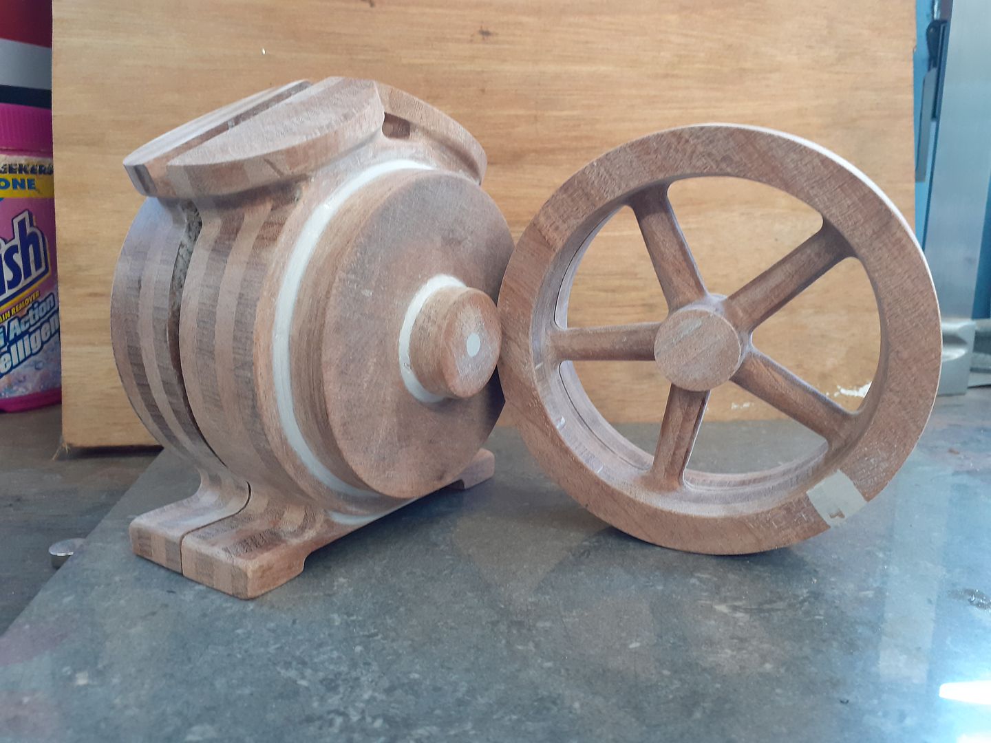
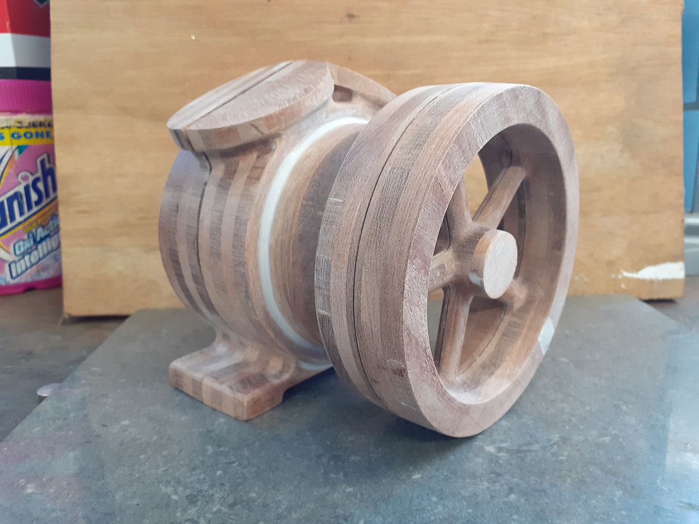
Here are the two halves together with the crankcase pattern.
For those that like their facts and figures, the total distance that all the cutters moved was 64.45m, time taken was 2hrs 5mins and I was left with 29.8mm of the original round disc. Luckily F360 spits out the G-code which I'm rather grateful for as the talk of writing the code had always put me off and I hate to think what it would have been like to write the 50,003 lines of code Fusion tells me it took to cut the part. Approx 50% of that was the internal finish and 40% the external ramp. |
| JasonB | 25/11/2020 19:11:20 |
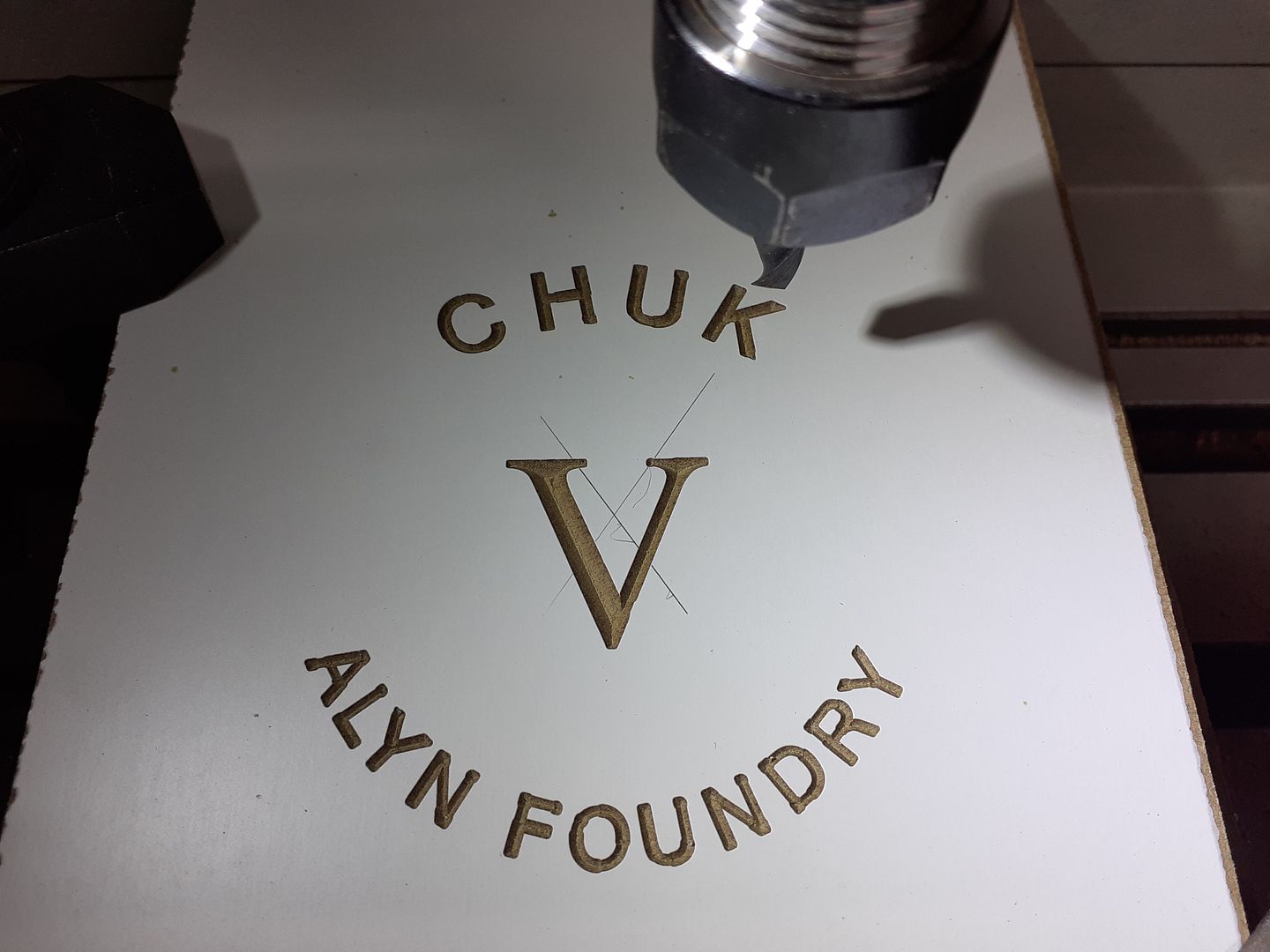
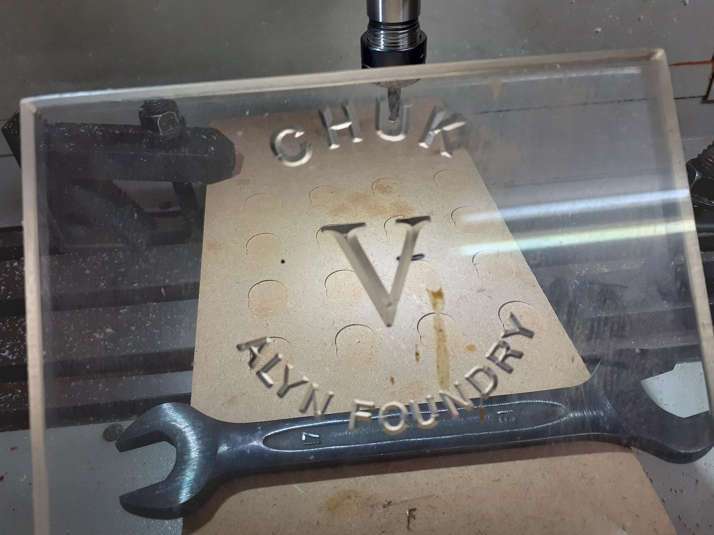
25215 forum posts 3105 photos 1 articles | The final pattern required was the cover plate to enclose the open side of the crankcase, Graham had said that it would be nice if the writing could be engraved allowing the builder to fill it with paint and buff up the surface if they wanted to rather than his usual raised "CHUK" that can be found on the other engines in the series. I have not found a way to get lettering in Alibre to follow a curve so ended up manually placing each letter using a couple of guide circles and tilting & spacing the letters so that they looked right. The 3D model was then exported to F360 which has an engrave function that produces some nice crisp corners to the letters rather than the rounded ends you would get if the a milling cutter just followed a single line. It does this by ramping the Vee shaped cutter down into the letter and up each of the corners. This video of part of the simulation shows it better than I can explain it. I thought I would do a test run first to see how the lettering looked so slipped an off cut of 6mm melamine faced MDF into the mill as this gives a good contrast.
A wooden pattern may have been prone to damage so I had some 10mm clear acrylic of some unknown parentage so decided to see how this cut. I was a bit worried that I may end up with a glob of molten plastic wrapped around the end of the tool but it cut nicely at 5000rpm and a feed of 200mm/min using a carbide chamfer mill. I actually ran the path twice giving an undersize tool height so that the second pass would cut slightly deeper but just leave a slight rounding to the corners of the letters so the sand would not get stuck.
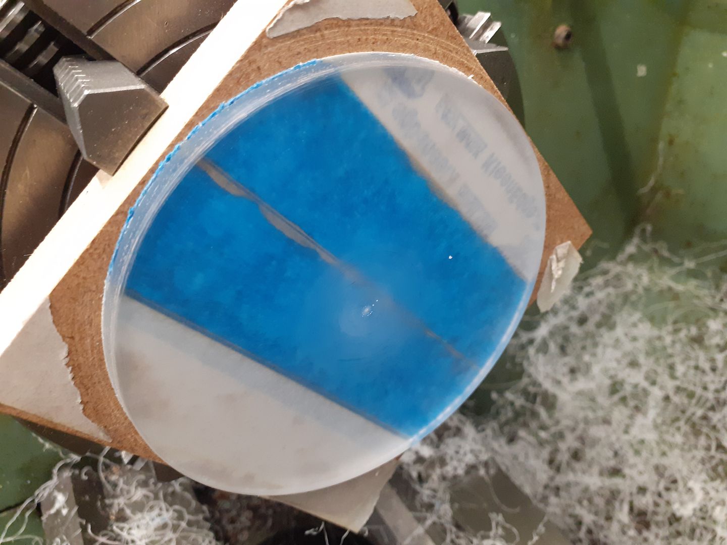
The 10mm material was too thick for the pattern so I cut out a rough circle on the vertical bandsaw and stuck it to some MDF using the two layers of easy peal tape and superglue sandwich method. The MDF was then held in the 4-jaw and the test letters turned off as the thickness was brought down to 6mm and the edge turned round with a slight draft angle.
It was then just a case of clamping the MDF to the mill table, locating the middle of the disc and running the cut again The tape separated quite easily and there was hardly a burr to be removed.
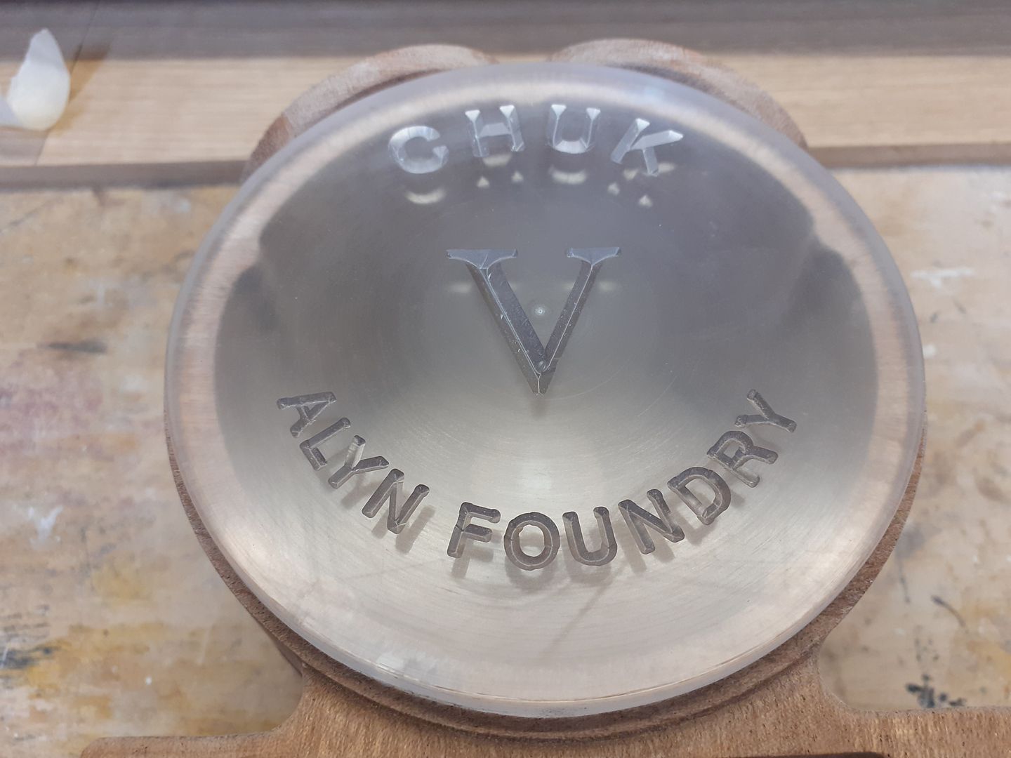
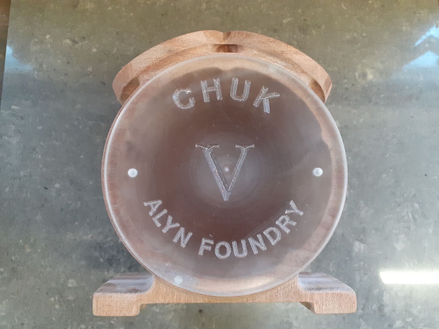
Here it is up against the crankcase, you may be able to see a couple of blind holes at 3 & 6 o'clock these were drilled in from the back so the pattern can be pulled from the mould with a couple of screws. And if you look really hard you can see two filled holes in the edge of the crankcase at 1 & 7 o'clock. These were holes drilled in past the joint line which had brass dowels located in one half to help line up the pattern halves when moulding them up.
Edited By JasonB on 25/11/2020 19:11:54 |
| Alyn Foundry | 26/11/2020 15:55:58 |
10 forum posts 6 photos | From the patterns.... To castings.... Errm, how do you attach a photo? |
| JasonB | 26/11/2020 16:05:13 |
25215 forum posts 3105 photos 1 articles | Allow me
|
| derek hall 1 | 26/11/2020 16:07:47 |
| 322 forum posts | Fantastic work .......(applauds).... |
| JasonB | 01/12/2020 12:31:40 |
25215 forum posts 3105 photos 1 articles | Get 'em while they are hot. First casting from the flywheel pattern looks to have come out OK.
|
| Ron Laden | 05/12/2020 07:25:22 |
2320 forum posts 452 photos | Morning Jason, the castings look good and the lettering to, the flywheel looks very clean also. I asked about the size of the engine which you told me but I should have asked what the bore size is. Ron |
| JasonB | 05/12/2020 07:36:32 |
25215 forum posts 3105 photos 1 articles | Morning Ron, the early CHUK engine drawings showed the bore as 1.5" but ones built recently have pushed that up to about 42mm which is the most that can safely be cut out of the casting as the larger the bore the better they run. Once I have my castings I'll mock up the engine and take a photo with a rule and can of drink in the shot to give an idea of size. Now that the first flywheel has been cast to prove the pattern the foundry are going to run off a batch and once Graham has those he will send my set as one package, I'm also buying a couple more flywheels as they are good size to go with my 24mm bore engines. Hopefully should get them this side of Xmas. |
| Ron Laden | 05/12/2020 07:52:16 |
2320 forum posts 452 photos | That's a decent size engine with twin 42mm bore, I guessed about 50mmm stroke which comes out at about 140 CC (I think) that's a good size. |
| Alyn Foundry | 05/12/2020 11:31:19 |
10 forum posts 6 photos | Posted by Ron Laden on 05/12/2020 07:52:16:
That's a decent size engine with twin 42mm bore, I guessed about 50mmm stroke which comes out at about 140 CC (I think) that's a good size. Good morning Ron. Perhaps you missed my earlier post on this thread? I'd also attached a link to a short video of CHUK 3 that uses my" improved " rotary valve arrangement. As Jason has pointed out the prototype had a rather small bore diameter but after meeting up with Bob Sier at an exhibition, he'd built one himself, he suggested a much bigger bore to get more power from the available atmospheric pressure. Cheers Graham.
|
| Alyn Foundry | 05/12/2020 11:53:01 |
10 forum posts 6 photos | For clarification the CHUK range of engines are Vacuum engines, or flame gulpers. Specifically designed for novice or entry level modellers. Here are some links to the engines running. https://youtu.be/S13wymzV0po https://youtu.be/wIM7pErrFCc https://youtu.be/CyouJxF6dpI Cheers Graham. |
| Ron Laden | 05/12/2020 17:22:51 |
2320 forum posts 452 photos | Sorry Jason/Graham I should have read the full thread which I now have. Ron |
.JPG)
.JPG)
.JPG)


.JPG)
.JPG)
.JPG)
Please login to post a reply.
Magazine Locator
Want the latest issue of Model Engineer or Model Engineers' Workshop? Use our magazine locator links to find your nearest stockist!
Sign up to our Newsletter
Sign up to our newsletter and get a free digital issue.
You can unsubscribe at anytime. View our privacy policy at www.mortons.co.uk/privacy
Latest Forum Posts
- *Oct 2023: FORUM MIGRATION TIMELINE*
05/10/2023 07:57:11 - Making ER11 collet chuck
05/10/2023 07:56:24 - What did you do today? 2023
05/10/2023 07:25:01 - Orrery
05/10/2023 06:00:41 - Wera hand-tools
05/10/2023 05:47:07 - New member
05/10/2023 04:40:11 - Problems with external pot on at1 vfd
05/10/2023 00:06:32 - Drain plug
04/10/2023 23:36:17 - digi phase converter for 10 machines.....
04/10/2023 23:13:48 - Winter Storage Of Locomotives
04/10/2023 21:02:11 - More Latest Posts...
- View All Topics
Support Our Partners


Shopping Partners
Subscription Offer

Latest "For Sale" Ads
- Reeves** - Rebuilt Royal Scot by Martin Evans
by John Broughton
£300.00 - BRITANNIA 5" GAUGE James Perrier
by Jon Seabright 1
£2,500.00 - Drill Grinder - for restoration
by Nigel Graham 2
£0.00 - WARCO WM18 MILLING MACHINE
by Alex Chudley
£1,200.00 - MYFORD SUPER 7 LATHE
by Alex Chudley
£2,000.00 - More "For Sale" Ads...
Latest "Wanted" Ads
- D1-3 backplate
by Michael Horley
Price Not Specified - fixed steady for a Colchester bantam mark1 800
by George Jervis
Price Not Specified - lbsc pansy
by JACK SIDEBOTHAM
Price Not Specified - Pratt Burnerd multifit chuck key.
by Tim Riome
Price Not Specified - BANDSAW BLADE WELDER
by HUGH
Price Not Specified - More "Wanted" Ads...
Get In Touch!
Do you want to contact the Model Engineer and Model Engineers' Workshop team?
You can contact us by phone, mail or email about the magazines including becoming a contributor, submitting reader's letters or making queries about articles. You can also get in touch about this website, advertising or other general issues.
Click THIS LINK for full contact details.
For subscription issues please see THIS LINK.
Digital Back Issues


Donate

 Register
 Log-in
Model Engineer Magazine
- Percival Marshall
- M.E. History
- LittleLEC
- M.E. Clock

ME Workshop
- An Adcock
- & Shipley
- Horizontal
- Mill

Subscribe Now
- Great savings
- Delivered to your door

Pre-order your copy!
- Delivered to your doorstep!
- Free UK delivery!
All Forum Topics > Miscellaneous models > CHUK V From Concept to Castings & Beyond