Forum sponsored by:

Beginner's engine build. Simplex 5"g.
| Iain Bachey | 16/05/2020 09:00:19 |
 13 forum posts 11 photos | Hello all I hope you are well. This is my first post as I've been lurking and learning from you all for a while now I have recently completed a Boll Aero 18 which took me 5 weeks on and off to build, and I'm happy to say runs rather well. Therefore I'm moving onto my next bigger project. As im a fan of steam, I have just received the drawings to start fabrication of a Simplex 5" gauge locomotive. I'm very much looking forward to get cracking on with the components but I've come across an issue already and I'm not sure if I'm blowing it out of proportion. I'm hoping to make the sheet metal parts myself without buying laser cut items, mainly the frames, but the drawing requires 1/8" BMS. Now, I'm assuming BMS is Bright Mild Steel. I've searched high and low and can't find any BMS in the required dimensions. Here's my dilemma, would it be ok the fabricate the frames from 3mm Mild Steel sheet? How would this effect strength and how would 3mm material implicate dimensions of other common parts? Any help/advise will be very much appreciated. Many thanks, Iain. |
| Bazyle | 16/05/2020 11:16:42 |
 6956 forum posts 229 photos | Welcome to the forum. Don't forget to put a few details in you profile like roughly where you are located as it sometimes helps when eg recommending a supplier. 3mm will be thick enough you just have to keep a careful eye on whether it affects the fit of any other component. ps sorry about the delay in giving you a response. Getting up at 9am on a Saturday? have enough of that on a weekday. Edited By Bazyle on 16/05/2020 11:19:03 |
| Simon Collier | 16/05/2020 11:27:44 |
 525 forum posts 65 photos | 3 mm plate will be fine Iain. I don't know about the UK but 1/8 plate has not been around in Australia for a long time. Most people use 3 mm plate, just ordinary black. Strength will not be an issue and Simplex frames aren't very long anyway. Just make the frame stretchers and anything else affected longer to suit. |
| Jon Cameron | 16/05/2020 11:30:36 |
| 368 forum posts 122 photos | Simplex has a lot of known errors in the drawings, there is a page which details all the known errors, for example the cutouts for the hornblocks are dimensioned incorrectly, if you look on the plans for the hornblocks and the frames you'll see what I mean however I'm not sure if your working from a bought set of plans or the articles themselves. As I think there are differences between the two. I don't have the link to hand but I'm sure someone here will be able to post it or I can have a search for it. As for frame steel 3mm bright steel is fine, 3mm black could be used but its more work involved in squaring the frame edges. You will have to adjust dimensions to suit the difference in frame material thickness, such as frame spacer and hornblocks, been an outside cylinder loco I suggest that you make the outside dimensions of the frames the same as the plans, adjusting the frame spacer width and the buffer angle width to suit, as well as making sure that the hornblocks sit the correct width. this will make setting up cylinders and valve motion brackets a lot simpler. Jon |
| Jon Cameron | 16/05/2020 11:45:18 |
| 368 forum posts 122 photos | Here's a link to the errors, solutions, and missing dimensions also. http://www.nlsme.co.uk/Simplex/simplexprobs.htm Jon Edited By Jon Cameron on 16/05/2020 11:45:42 |
| Andrew Johnston | 16/05/2020 11:46:28 |
 7061 forum posts 719 photos | Sheet and plate are one of the few forms of material that have gone exclusively metric. The hornplates on my traction engines were specified as 1/4" plate, but I had to use 6mm. I'd second the advice from Jon and keep the outside frame dimension the same. That's what I did on my traction engines, so all I had to adjust was the width of a couple of castings. I also slightly altered the crankshaft bearing housings to keep the crankshaft and valve gear in the same place relative to the engine centre line.. Andrew |
| Iain Bachey | 16/05/2020 12:55:38 |
13 forum posts 11 photos | Thanks for all the reply chaps. I appreciate all the good advice. As a newbie I'll need all the help I can get. I'll go for 3mm BMS or if not, Mild Steel as that seems to be readily available from many suppliers. Also good advice about keeping the outboard dimensions the same and adjust any inboard parts to suit, such as the frame stretchers and buffer beam angles. In my line of work I'm used to working to very close tolerances and not deviating from drawings what so ever, without approval from the OEM! I don't want to get too bogged down with imperial to metric sizes during this project as Simon mentioned, imperial material has dissapered almost. Thanks again for all the help so far, I'll keep you all posted on my progress and add photos as I go. First job, order some material. Regards, Iain. |
| Clive Brown 1 | 16/05/2020 13:12:23 |
| 1050 forum posts 56 photos | I built my Simplex over 25 years ago. The main error I remember in the drawings related to dimensioning of the motion plate brackets and / or the slide bar length. I needed to re-make some of these components. The error was acknowledged by Martin Evans in the ME series, but the drawings were never altered AFAIK. I can't now remember the exact detail. Was it that the 1 3/32" horizontal dimension should be 1 3/16"? Perhaps someone-else has a better memory. The other irritation was that the L/H main-frame drawing wasn't shown with a hole for the lubricator oil-pipe, so I had to drill one after assembly and painting. Other than those points, I found building to the design OK. TBH, I don't recall the hornblock errors mentioned above. Most of the points on the linked article seem to be lack of detail which can be dealt with as the build progresses. Not unusual with ME model loco designs perhaps. |
| Brian Baker 1 | 16/05/2020 14:08:11 |
 229 forum posts 40 photos | Greetings, I have seen and driven many Simplexs, and they have all been good performers, which left their owners with big grins. Yes, there are a few errors and this is to be expected on any design. I not sure if you know, but you can order many parts, laser cut, for this locomotive from Model Engineers Laser, and they will give reliably cut parts and show a considerable reduction in build time. Good luck regards Brian Baker |
| David Wasson | 23/05/2020 15:02:42 |
 149 forum posts 43 photos | I don't know how deep you are into your project, but, you might consider the Super Simplex. Evans corrected a few design errors on the Simplex and created the Super Simplex later on. Either design is a great first time locomotive and fun to drive. I have created a website dedicated just to the Super Simplex and has manys things in common with the Simplex. If you are building a "regular" Simplex you might still find some of the information useful. David |
| Iain Bachey | 23/05/2020 21:56:08 |
13 forum posts 11 photos | Hi all. I've cut the first bit if metal today! I'm still waiting for the frame material but I have material for the buffer beams, so that's where I've started First job was to fasten my vice to the bench and fabricate new aluminium jaws so I don't damage and steel parts! I have seen the Super Simplex David, but I've bought the drawings for the Simplex and got into the mindset of building that now, that was after plenty of research too! I will pop a picture on when I figure out how Iain. |
| Jon Cameron | 24/05/2020 16:46:09 |
| 368 forum posts 122 photos | Hi, To post pictures go to albums at the top of this page, create a gallery and click to add photos select from your device where there uploaded from and click upload once all are selected . Then when you post click the camera button and insert the photos from your album. Hope this helps. There is also a good build thread for the chassis can be found here. The error.on the axleboxes which may not apply to the drawings and only the magazine articles is with the height of the fabricated horns doesn't match the correct the height of the frame cut out. Use the frame dimension and build the horns to that size. Edited By Jon Cameron on 24/05/2020 17:03:46 |
| Iain Bachey | 24/05/2020 19:30:23 |
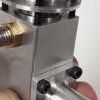
13 forum posts 11 photos | Thanks Jon. Good advice. I've not got round to fully explore the drawings yet. I've been fabricating the buffer beams again today. They are the correct size and the finish is good considering I don't have a milling machine, yet, so I used the lathe with a vertical slide and finished off shaping them by hand. Still waiting for the frame material, expecting it mid week.
I used the surface plate to check for a straight finish using a 0.0015" feeler gauge for accuracy
Regards, Iain. Edited By Iain Bachey on 24/05/2020 19:43:58 Edited By Iain Bachey on 24/05/2020 19:52:40 |
| Iain Bachey | 24/05/2020 19:50:41 |
13 forum posts 11 photos | As mentioned in an earlier post, and seeing how job helped me with the photo uploading, here's the vice jaws I made out of aluminium
Regards, Iain. Edited By Iain Bachey on 24/05/2020 19:51:09 |
| Iain Bachey | 26/05/2020 23:12:14 |
13 forum posts 11 photos | I've been having a look at the Simplex frame drawing, and as previously reported, there's a fault with the horn block dimensions. As I'm a newbie I would have just fabricated the parts as shown. Below is the area on the drawing where the reported error is. It shows the hornblock as 1 1/2" then the upper plate a s 1/8". The next photo shows the axlebox cut out as 1 5/8".
Is the top plate supposed to be flush with the axlebox upper cut out or slightly lower, 1/8" lower? Regards. Iain.
|
| David Wasson | 27/05/2020 00:20:41 |
149 forum posts 43 photos | The horn blocks should be made to match the frames. Hornblocks should be 1-5/8" , not 1-1/2". |
| Iain Bachey | 27/05/2020 00:43:38 |
13 forum posts 11 photos | Thanks David. I'll pencil it in on the drawing. Hoping to get both frames cut out to the correct rectangular dimensions tomorrow as the material arrived today |
| David Wasson | 27/05/2020 01:19:09 |
149 forum posts 43 photos | This dimension is confirmed in ME Dec 1968 for cast horn blocks also. The opening should be 1-5/8" by 1-1/4". |
| Jon Cameron | 27/05/2020 09:09:43 |
| 368 forum posts 122 photos | Hi, Yes as David says, it needs to be 1.5/8" to match the opening of the slot. the 1/8" top plate needs to have its lower edge flush with the top opening of the slot. Id also check the hole for the oil to the axle block as I remember something not aligning there quite right. But I may be mistaken on that one, and it was how Id drawn it in CAD that caused the issue??? Jon
|
| Derek Drover | 27/05/2020 10:38:16 |
| 90 forum posts | A couple of mods that are worth considering are sealed needle roller bearings on the axles (the axleboxes are very large), and instead of having an ashpan which drops as a whole and is difficult to seal to the boiler foundation ring, fabricate a fixed ashpan with a tipping grate. This I have done on mine and it works very well... so far virtually no ash landing on the rear axle/axleboxes. Also, split your running boards to allow valve timing adjustment without the need to remove the side tanks... saves ALOT of effort !!
Rgds Del. |


Please login to post a reply.
Magazine Locator
Want the latest issue of Model Engineer or Model Engineers' Workshop? Use our magazine locator links to find your nearest stockist!
Sign up to our Newsletter
Sign up to our newsletter and get a free digital issue.
You can unsubscribe at anytime. View our privacy policy at www.mortons.co.uk/privacy
Latest Forum Posts
- *Oct 2023: FORUM MIGRATION TIMELINE*
05/10/2023 07:57:11 - Making ER11 collet chuck
05/10/2023 07:56:24 - What did you do today? 2023
05/10/2023 07:25:01 - Orrery
05/10/2023 06:00:41 - Wera hand-tools
05/10/2023 05:47:07 - New member
05/10/2023 04:40:11 - Problems with external pot on at1 vfd
05/10/2023 00:06:32 - Drain plug
04/10/2023 23:36:17 - digi phase converter for 10 machines.....
04/10/2023 23:13:48 - Winter Storage Of Locomotives
04/10/2023 21:02:11 - More Latest Posts...
- View All Topics
Support Our Partners


Shopping Partners
Subscription Offer

Latest "For Sale" Ads
- Reeves** - Rebuilt Royal Scot by Martin Evans
by John Broughton
£300.00 - BRITANNIA 5" GAUGE James Perrier
by Jon Seabright 1
£2,500.00 - Drill Grinder - for restoration
by Nigel Graham 2
£0.00 - WARCO WM18 MILLING MACHINE
by Alex Chudley
£1,200.00 - MYFORD SUPER 7 LATHE
by Alex Chudley
£2,000.00 - More "For Sale" Ads...
Latest "Wanted" Ads
- D1-3 backplate
by Michael Horley
Price Not Specified - fixed steady for a Colchester bantam mark1 800
by George Jervis
Price Not Specified - lbsc pansy
by JACK SIDEBOTHAM
Price Not Specified - Pratt Burnerd multifit chuck key.
by Tim Riome
Price Not Specified - BANDSAW BLADE WELDER
by HUGH
Price Not Specified - More "Wanted" Ads...
Get In Touch!
Do you want to contact the Model Engineer and Model Engineers' Workshop team?
You can contact us by phone, mail or email about the magazines including becoming a contributor, submitting reader's letters or making queries about articles. You can also get in touch about this website, advertising or other general issues.
Click THIS LINK for full contact details.
For subscription issues please see THIS LINK.
Digital Back Issues


Donate

 Register
 Log-in
Model Engineer Magazine
- Percival Marshall
- M.E. History
- LittleLEC
- M.E. Clock

ME Workshop
- An Adcock
- & Shipley
- Horizontal
- Mill

Subscribe Now
- Great savings
- Delivered to your door

Pre-order your copy!
- Delivered to your doorstep!
- Free UK delivery!
All Forum Topics > Locomotives > Beginner's engine build. Simplex 5"g.