
Power feed for a VM32L mill
With full CNC later, maybe?
| Iain Downs | 18/04/2020 17:58:23 |
| 976 forum posts 805 photos | Hi, there. I recently took delivery of what for me is a BIG mill. VM32L which is pretty much the same size as WM18. Whilst, I love the size of the table and being able to have a couple of areas on it, it's quickly become obvious that a Y axis power feed would make life much easier. So I'm going to make one. But I need some help! As a background, I've already built a CNC system for my (much much) smaller CMD10 mill. Even to the point of writing my own CNC driver and controller (I'm a software keep by profession even if demoted to just talking to people in my old age). What I have in mind is to build the electronics (arduino) with 3 axis in mind, but only one motor for now. I have some TB6600 drivers a 24V 20A supply and a bunch or arduinos. I expect I will control it from an old android tablet with a Xamarin program. So arduino (Iain's Code) to drive the driver and a simple app to pick speed and stuff on the tablet. So what am I missing? I thought this would be a decent motor. I think it's overkill but it's not much more expensive than a smaller one and maybe the Z would need it. I'm thinking that I either want to have a clutch which can disconnect the motor from the leadscrew when I want to be manual, or to have a relay or similar which can disconnect power to the motor. In this case I would arrange it so that when the power was turned off, the relay would disconnect the connections to the motor (after a second or so). I kind of prefer the mechanical approach, but have no idea how to go about it. I'm thinking some kind of clutch, I'm thinking something with splines. I'm thinking it sounds very complex and hard to make. I'm thinking I could do with some advice! The second think that would be useful is a drawing or model of the endcap (if that's the right word) that the handle is connected to. I can take it off and measure it up, of course, but I doubt my accuracy and it would be irritating to make a frame and find that it doesn't fit. Any advice or pointers would be much appreciated.
Iain |
| Martin Connelly | 18/04/2020 18:18:46 |
 2549 forum posts 235 photos | If you are going to create a controller program on the Android tablet why not emulate one of the pendants used on a CNC machine. These give fast motion or jog. Jog is selectable for steps such as 1mm, 0.1mm, 0.01mm and 0.001mm. With a manual pulse generator (mpg) there is also an option for a slower motion with speed controlled by the rate the mpg is turned. It may be easier than designing a clutch if the programming is possible. There is a software version in Mach3 that you could look at for ideas as well. Martin C |
| Iain Downs | 19/04/2020 10:52:39 |
| 976 forum posts 805 photos | I probably will put a jog option on it, but I feel I need to be able to move by hand for somethings where I need to 'feel' my way into a piece and back off if things look like they are going west. One thing which confuses me is that the the motor referenced above claims 4.2A and 2.96V. Why, therefore, am I considering a 24V power supply?
Iain |
| Iain Downs | 20/04/2020 20:37:26 |
| 976 forum posts 805 photos | This is the sort of thing I had in mind..
The idea is that the motor moves forward on the bars and engages the pins. You'd need a lock of some kind and I don't know if pins would be better than a wedge or bar. Youu can't see it, but the two timing pulleys aren't quite in line (imagine the belt, that's beyond my 3d skills!), so it still needs a bit of fettling.
Iain |
| SillyOldDuffer | 20/04/2020 22:20:22 |
| 10668 forum posts 2415 photos | Hi Iain, Gremlins got at the motor link in your first post and doubled the URL. Should be. 2.96V is the DC voltage needed to maintain the current (4.2A) in order to produce the motor's rated holding torque, ie ability to resist turning when stopped. The watts expended on holding won't overheat the motor within these limits. Normally though stepper motors are turned by pulsing the windings rather than held stopped with a constant current. Best step performance is achieved by getting the motor up up to rated current as quickly as possible. As the edge of a pulse rises faster with increased voltage it's usual to run the controller distinctly higher than the motors holding voltage and, because this could cause overheating, to keep the motor within ratings by managing the current. So the T6600 controller uses DIP switches to clamp the maximum current it will deliver irrespective of the input voltage. With stepper motors amps and pulse rates matter more than volts and they work better when the controller has plenty of volts so the amps can be delivered quickly. Rather than slide the whole motor, how about fitting a dog clutch between the motor and mill? Could a pair of contrate gears where one is slid to engage the other by a lever, or just a pair of bolted discs that the operator unscrews manually. Dave
|
| John P | 21/04/2020 09:52:42 |
| 451 forum posts 268 photos | I have two similar disconnects on stepper motor drives to go from John
|
| Alan Jackson | 21/04/2020 10:43:32 |
 276 forum posts 149 photos | Hi Iain, This approach might solve your problem; the worm attached to the stepper motor shaft can be rotated on its eccentric mounting to engage or disengage with the worm wheel on the feed screw. You also get a good reduction drive (say 20 :1) to give a slow speed and high torque. The stepper motor speed seems to be just about right. Alan
Edited By Alan Jackson on 21/04/2020 10:44:03 |
| Martin Connelly | 21/04/2020 11:29:13 |
2549 forum posts 235 photos | Iain, I think tentatively milling is a good way to get an uneven finish and rapidly worn, chipped and blunted cutters. One of the thing CNC milling encourages you to do is learn about feeding at the correct rate to get good cutting processes and avoid rubbing or undersized chips that mean you are not using cutters as they were designed to be used. Look at what Jason is doing with his build logs, no feeling his way in to the material there. Martin C |
| Bazyle | 29/05/2020 13:27:23 |
 6956 forum posts 229 photos | I know this thread is a little old but I came across it looking for something else. Looked at the picture above by Alan. |
| JasonB | 29/05/2020 13:32:12 |
 25215 forum posts 3105 photos 1 articles | Have a look in Alan's album, there are a couple of his "Stepperhead" machine with swarf on it |
| Iain Downs | 29/05/2020 15:39:18 |
| 976 forum posts 805 photos | Hi, all. Prompted by Bazyle's post, I thought I'd tell you where I'm up to with this. This is what I plan to build
I'll replace the Y axis handle with a timing pulley, which will have a new handle bolted to it. I'm going to lose the graduations I think, but I've had news that my DRO kit may not be far off - and there's still the right hand handle. The timing belt (not shown) connects to a timing pulley held on a bearing. On the outside (left hand side) there is a 3 fingered dog clutch (three clawed?). The motor has a 3mm keyway with the other half of the dog clutch on.To engage I slide it forward and tighten a lock screw. To disengage move it back. I now have all the parts. I've built the electronics and the driver software on the arduino (well, I still have to include an acceleration profile and the code which stops when an end stop is reached). Even more I've tested it with a smaller stepper and it works! The big stepper arrived today. I've also got the pulleys, timing belt and the bearing. And probably enough stock metal to make the bracket. I'll post up a photo of the bits this weekend and of any progress I'm not too embarrassed about! Who knows, it may even work! I think the biggest challenge is going to be to get the motor lined up with the pulley so that the clutch engages correctly. Iain |
| Iain Downs | 29/05/2020 15:42:59 |
| 976 forum posts 805 photos | Oh! I forgot to ask if it is worth using shielded cable for the motor to reduce noise (which could affect the DRO when it arrives). If so is there any obvious source? This on ebay looks like the right stuff, though I'm not keen on cable with 3 black wires and one green. Iain |
| John Hinkley | 29/05/2020 16:09:16 |
 1545 forum posts 484 photos | Iain, You say you are motorising the Y-axis but refer to the "right hand handle". Do I take it that it's actually the X-axis that's getting the motor upgrade - i.e. left to right? I'd be inclined to do that one first, anyway. Much more useful in my opinion and experience, limited though that is. John
|
| Iain Downs | 29/05/2020 17:32:20 |
| 976 forum posts 805 photos | Yes, John. Left to Right I got the naming wrong here.
Iain |
| duncan webster | 29/05/2020 23:33:16 |
| 5307 forum posts 83 photos | If you're driving it with a direct (1:1) stepper motor you don't need to declutch to manual wind. I have a stepper on the X travel on my Centec, 0.1" pitch leadscrew. The motor makes it 'notch' at 0.0005" increments, but I'll live with that. |
| ChrisB | 30/05/2020 06:55:07 |
| 671 forum posts 212 photos | I think a clutch would be a good idea Duncan. Although as you said, if the motor is a direct drive the resistance will be low, there still is a noticable resistance and worse than that, when you turn the handwheel you are feeding back some kind of voltage as I can see all the lights on the control box flickering. I chose to make a simple friction disk clutch which serves a dual purpose, apart from decoupling the motor, it will slip if the load is too much or the end stop is reached. |
| Iain Downs | 02/06/2020 20:53:26 |
| 976 forum posts 805 photos | So I've got my design and I've started off. The first step was the electronics, which looks like this
The motor on the far left is a much smaller test motor. The bigger beast next to it is the real deal. Two oddities are the switch which appears to light up when off. Hadn't expected that (or have any idea where it cam from) and the motor drive socket is too high, the switch interferes with the eject button. it still seems to work with a bit of a wiggle, though.
And the working bits. On the left an arduino nano on some veroboard. I'm afraid I've never got to grips with making PCBs so it's old school. At the bottom a 24V 15A power supply and the black box claims to be a TB6600 drive. One thing I forgot when designing the front panel was indicators, so I'll be drilling more holes soon. Incidentally, the way I made this was to do a design in OnShape, make a drawing, stick it to a piece of aluminium plate and drill, file and whatever against the template. Some of my filing's a bit rough, but it's hidden by the DB9. All of these bits (apart from the motor I already had. Next the hardware side
The flat bits are for the mounts, the wide round steel bar for the dog clutch, the thin bar for the axle, the aluminium bit (probably) for the new handle and the pulleys, belt and bearing are obvious. The plans are shown below
Obviously the timing belt is missing between the two pulleys. THe first thing to make is the backplate
And the rest of the frame. The dog clutch is the only other difficult part (I hope)
Iain |
| Iain Downs | 02/06/2020 21:04:11 |
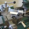
| 976 forum posts 805 photos | And I've already started The big bit of 12mm hot rolled plate needs to be cut down, faced and then further machined. FIrst cut on the Femi bandsaw (I love this machine!)
Which is all very well for cutting to length, but it's still too wide. So I dragged out my franken-grinder. I build this before I had a chop saw (which melted) or finally invested in the femi, It wasn't a whole-hearted success on thicker items, but it was designed to be able to cut long pieces.
This is an action photo. For the sake of those with weak stomachs let me say it was hot and I was wearing shorts. Sorry about the legs...
I got better sparks at the top of the cut and it's only by chance that the wife came in and was persuaded to take this (not very flattering) photo. Next to thin down to 10mm
Mark out
And cut the slots and corner relief.
Although I've marked out the hole for the bearing, I was really worried about how I could make sure it lined up with the motor spindle. I eventually thought that the best approach was to hold the backplate and motor plate together and drill through both to provide an accurate hole to work from. Lets see how well that works. Finally to cut out the un-needed L part. This was on my recently made bandsaw table which worked rather better than I expected (in fact I tend to be quite pleased when things I make work at all! Perhaps I'm improving).
and the result (so far)
I've cut it a bit oversize so I can clean up on the mill and match this to the motor plate. So far so good!
Iain |
| Iain Downs | 10/06/2020 20:11:12 |
| 976 forum posts 805 photos | Rightio. A bit intermittent over the last week, but progress has been made. Here's the backplate (as above) plus the motor mount. I got the motor mount trimmed to match the backplate and then clamped them together to drill holes for bolts and, more importantly as pilots so to speak for the bearing and motor itself.
The motor plate motor recess was done on the lathe - spending (much) more time centering the 4 jaw than actually machining.
I swear that I get the direction to move the piece wrong at least one time in three! The hole for the bearing in the backplate was done with a boring head, the new mill being a MUCH more pleasant instrument to use it on than the tiny CMD10. One thing which was less good was that my (fairly) new co-axial indicator seems to be positioning the head a bit to the right of the actual centre. I can't even imagine a mechanism for this, but checking with a dial test indicator seems to suggest this. For now, I'm ignoring this issue, but I will need to review sometime soon I've also cut the axle to size, bored out the pulleys and started work on the dog chucks. The idea is to cut them on the mill in a hex ER32 collet, so I've cut a 40mm x 18mm cylinder as the support for a 40x10 cylinder. One done so far. I can't really take a cut bigger than 0.5mm on my lathe so it takes quite a while to reduce from 40 to 18, You can see the first one in the bottom right Here are most of the bits.
Tomorrow, with some luck, complete the preparations for the dug chuck. Not sure I'll get to cut the faces though.
Iain |
| Iain Downs | 14/06/2020 15:19:39 |
| 976 forum posts 805 photos | The more recent work for this has been mainly on the dog clutch. Sadly this turned out to be more of a dog's dinner as you will see. The idea was to make a long stem for the dog clutch which could be held in an E32 collet for cutting the faces. You can just see one of the in the last photo in the previous post. Here is the face of the dog clutch being reduced (the clutch is 10mm high, 1 5mm plate and then 5 mm of doggy bits).
Here are the 2 parts with the Hex ER32 collet holder in the background.
And this is a complete mess.
The one on the right was my first attempt. It's not going to win any canine awards, I can tell you. The stupid thing I did was to rotate the holder by 6 degrees not 120, which doesn't work. I missed that in the otherwise rather good You Tube video which told me what to do. The second mess up ( on the left) was just because I didn't tighten the chuck enough and it span. However, the second shot worked rather better.
I had to do a bit of trimming with a file, as the lands were a littl bite too big, but better that than too small where it would rattle. The parts fit nicely together in all three orientations (after a little fettling) and there is only a barely perceptible slack. Here's all the bits I've made so far and you can start to see how it fits together.
The only major thing left to do is to cut keyways for the leadscrew and the motor clutch. I've decided to leave this for now as, although I've made the keyway cutters, I want to make a spindle lock for the mill before I cut the keyways. Then the terrifying part - put it all together and see if the bits line up without too much 'help'.
Iain |


Please login to post a reply.
Want the latest issue of Model Engineer or Model Engineers' Workshop? Use our magazine locator links to find your nearest stockist!
Sign up to our newsletter and get a free digital issue.
You can unsubscribe at anytime. View our privacy policy at www.mortons.co.uk/privacy
- hemingway ball turner
04/07/2025 14:40:26 - *Oct 2023: FORUM MIGRATION TIMELINE*
05/10/2023 07:57:11 - Making ER11 collet chuck
05/10/2023 07:56:24 - What did you do today? 2023
05/10/2023 07:25:01 - Orrery
05/10/2023 06:00:41 - Wera hand-tools
05/10/2023 05:47:07 - New member
05/10/2023 04:40:11 - Problems with external pot on at1 vfd
05/10/2023 00:06:32 - Drain plug
04/10/2023 23:36:17 - digi phase converter for 10 machines.....
04/10/2023 23:13:48 - More Latest Posts...
- View All Topics


- Reeves** - Rebuilt Royal Scot by Martin Evans
by John Broughton
£300.00 - BRITANNIA 5" GAUGE James Perrier
by Jon Seabright 1
£2,500.00 - Drill Grinder - for restoration
by Nigel Graham 2
£0.00 - WARCO WM18 MILLING MACHINE
by Alex Chudley
£1,200.00 - MYFORD SUPER 7 LATHE
by Alex Chudley
£2,000.00 - More "For Sale" Ads...
- D1-3 backplate
by Michael Horley
Price Not Specified - fixed steady for a Colchester bantam mark1 800
by George Jervis
Price Not Specified - lbsc pansy
by JACK SIDEBOTHAM
Price Not Specified - Pratt Burnerd multifit chuck key.
by Tim Riome
Price Not Specified - BANDSAW BLADE WELDER
by HUGH
Price Not Specified - More "Wanted" Ads...
Do you want to contact the Model Engineer and Model Engineers' Workshop team?
You can contact us by phone, mail or email about the magazines including becoming a contributor, submitting reader's letters or making queries about articles. You can also get in touch about this website, advertising or other general issues.
Click THIS LINK for full contact details.
For subscription issues please see THIS LINK.


 Register
 Log-in
Model Engineer Magazine
- Percival Marshall
- M.E. History
- LittleLEC
- M.E. Clock

ME Workshop
- An Adcock
- & Shipley
- Horizontal
- Mill

Subscribe Now
- Great savings
- Delivered to your door

Pre-order your copy!
- Delivered to your doorstep!
- Free UK delivery!