Forum sponsored by:

milling crankshaft on cnc mill using A axis
| geoff adams | 02/02/2020 15:54:35 |
| 214 forum posts 207 photos | .jpg")  |
| JasonB | 02/02/2020 16:46:10 |
 25215 forum posts 3105 photos 1 articles | That is better than the usual thump, thump, thump of turning from the solid. I wonder if a flat ended ctr cutting bit would work better than the rounded one you were using as the cutting speed at the edge of the tool should be faster. For those interested the program is one the late John S wrote and used to demo the Sieg CNC machines at shows. Works straight out of the box for machines like the Sieg that have their 4th axis on the right but needs a slight tweak if it is on the left. |
| fizzy | 02/02/2020 17:28:52 |
 1860 forum posts 121 photos | that would make life simple...if only I ever dared to fit my 4th axis. Why not go the whole way and cut to size with a flat tool? Surely a good finish is possible? My cnc computer got filled with dust and went pop earlier in the week so had to drill 300 holes by hand, awful job! Time to build a decent enclosure for the pc and driver box so it doesnt happen again. Theyre great when they work!
|
| geoff adams | 02/02/2020 17:43:59 |
| 214 forum posts 207 photos | the cutter is an 8mm flat slot drill i think its the video gives the impression its a rad cutter Geoff |
| Emgee | 02/02/2020 17:45:46 |
| 2610 forum posts 312 photos | Jason Is the crankshaft program available from your Dropbox with a link please ? Emgee |
| JasonB | 02/02/2020 17:50:08 |
25215 forum posts 3105 photos 1 articles | Can be copied from the first post in this thread, also a Linux version further on, JS's was for Mach3 |
| Martin Connelly | 02/02/2020 18:32:13 |
 2549 forum posts 235 photos | F50 G19 G01 X0 Y0 Z10 A0 G060 A360 Y0 Z10 K10 G17 M30 Try this. Gives the required motion. Simple to understand. I could add parameters to allow for throw and pin radius and offset for subsequent pins. This will currently give a zero diameter pin with stroke of 20 if the bottom of the cutter is on the a axis centre line when z=0. Bottom of the cutter 3mm above a axis centre line at z=0 gives a 6mm diameter pin. Martin C
Edited By Martin Connelly on 02/02/2020 18:34:52 |
| Andrew Johnston | 02/02/2020 18:49:39 |
 7061 forum posts 719 photos | Posted by fizzy on 02/02/2020 17:28:52:
Why not go the whole way and cut to size with a flat tool? Surely a good finish is possible? Standard endmills and slotdrills are not flat on the end. They're slightly hollow ground, so you end up with a barrel shaped crankpin not a cylindrical one. The problem can be ameliorated, but not eliminated, by offsetting the cutter. Andrew |
| Martin Connelly | 02/02/2020 19:12:41 |
2549 forum posts 235 photos | F50 G19 G01 X0 Y0 Z10 A0 G02 A360 Y0 Z10 K10 G17 M30 Fixed the G02 line. Didn't see the corruption caused by editing the line. Martin C |
| Martin Connelly | 02/02/2020 19:57:49 |
2549 forum posts 235 photos | F50 G19 G01 X0 Y0 Z10 A0 G02 A360 Y0 Z10 K-10 G17 M30 Added the minus sign in K-10 This is what happens when you type it in here before checking it in Mach3. Martin C Another thought, G02 may need to be G03 depending on the a axis positive direction. Edited By Martin Connelly on 02/02/2020 20:06:26 |
| Ian Johnson 1 | 02/02/2020 21:33:15 |
| 381 forum posts 102 photos | Great to see some 4th axis CNC and using a John Stevenson program too! Turned out nice. I use Vectric Vcarve which uses the Z axis as the A axis when rotary milling, bit of a cheat really because it is still only three axis milling not 4 axis. So I had to start writing my own programs for true 4 axis milling, nothing as ambitious as this though! I need to get my 4th axis plugged in, not used it for a while, I also need a tail stock support like yours before attempting something like a crank. Is it an optical illusion or is the cutter slightly off centre to the journal? Ian |
| old mart | 02/02/2020 21:50:21 |
| 4655 forum posts 304 photos | I take it that the finishing cuts after the photographs were taken were by resetting the Y axis two or three times to get the journals cylindrical. |
| Emgee | 02/02/2020 23:41:52 |
| 2610 forum posts 312 photos | Jason. Having read all posts on the MEM forum am I correct in thinking the first Mach3 posted code is functioning correctly provided direction of the A axis is correct ? Emgee |
| JasonB | 03/02/2020 06:57:18 |
25215 forum posts 3105 photos 1 articles | Emgee, Yes, that is the one Geoff used. Old Mart, no the middle of the pin is slightly raised due to the shape of the end teeth of a typical cutter as already mentioned by Andrew as the cutter always stays directly above the pin's ctr line by moving in the Y axis. Should also say that it was mostly written by Adam, John's son. |
| old mart | 03/02/2020 19:20:54 |
| 4655 forum posts 304 photos | No, Jason, if the cutter stayed above the pin centre line the centre of the pin would be larger. Clearly the cutter centreline was offset as the machining marks confirm, making the pin smaller in the centre. |
| JasonB | 03/02/2020 19:46:20 |
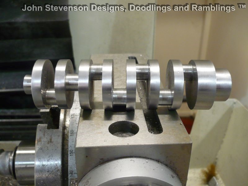
25215 forum posts 3105 photos 1 articles | I agree that the one Geoff has shown does appear to have fillets in the internal corners which suggests something is off, which is why I thought a ball nose cutter was being used. This is how one done by JS looks with no additional passes after running the code.
Originally posted by JS in this thread with sketches by Andrew of how Y follows the pin |
| old mart | 03/02/2020 20:34:02 |
| 4655 forum posts 304 photos | Is that a 7 cylinder engine with only 2 main bearings or what is it? |
| JasonB | 03/02/2020 20:48:23 |
25215 forum posts 3105 photos 1 articles | Read the thread. |
| old mart | 03/02/2020 22:17:14 |
| 4655 forum posts 304 photos | Found it eventually after the usual ramblings, just a demo. |
| geoff adams | 04/02/2020 06:33:09 |
| 214 forum posts 207 photos | Morning all from the replies it seems that i have the y axis off creating a fillet in the corner the a axis is left on the mill all the time i will check the set up this morning. mach 3 does lose it self, i relied on it remembering the y offset anyway off to specsaves this morning to pick up new glasses that might help will let you all know how i get after resetting and checking the setup and running another test piece thanks Geoff
|
Please login to post a reply.
Magazine Locator
Want the latest issue of Model Engineer or Model Engineers' Workshop? Use our magazine locator links to find your nearest stockist!
Sign up to our Newsletter
Sign up to our newsletter and get a free digital issue.
You can unsubscribe at anytime. View our privacy policy at www.mortons.co.uk/privacy
Latest Forum Posts
- *Oct 2023: FORUM MIGRATION TIMELINE*
05/10/2023 07:57:11 - Making ER11 collet chuck
05/10/2023 07:56:24 - What did you do today? 2023
05/10/2023 07:25:01 - Orrery
05/10/2023 06:00:41 - Wera hand-tools
05/10/2023 05:47:07 - New member
05/10/2023 04:40:11 - Problems with external pot on at1 vfd
05/10/2023 00:06:32 - Drain plug
04/10/2023 23:36:17 - digi phase converter for 10 machines.....
04/10/2023 23:13:48 - Winter Storage Of Locomotives
04/10/2023 21:02:11 - More Latest Posts...
- View All Topics
Support Our Partners


Shopping Partners
Subscription Offer

Latest "For Sale" Ads
- Reeves** - Rebuilt Royal Scot by Martin Evans
by John Broughton
£300.00 - BRITANNIA 5" GAUGE James Perrier
by Jon Seabright 1
£2,500.00 - Drill Grinder - for restoration
by Nigel Graham 2
£0.00 - WARCO WM18 MILLING MACHINE
by Alex Chudley
£1,200.00 - MYFORD SUPER 7 LATHE
by Alex Chudley
£2,000.00 - More "For Sale" Ads...
Latest "Wanted" Ads
- D1-3 backplate
by Michael Horley
Price Not Specified - fixed steady for a Colchester bantam mark1 800
by George Jervis
Price Not Specified - lbsc pansy
by JACK SIDEBOTHAM
Price Not Specified - Pratt Burnerd multifit chuck key.
by Tim Riome
Price Not Specified - BANDSAW BLADE WELDER
by HUGH
Price Not Specified - More "Wanted" Ads...
Get In Touch!
Do you want to contact the Model Engineer and Model Engineers' Workshop team?
You can contact us by phone, mail or email about the magazines including becoming a contributor, submitting reader's letters or making queries about articles. You can also get in touch about this website, advertising or other general issues.
Click THIS LINK for full contact details.
For subscription issues please see THIS LINK.
Digital Back Issues


Donate

 Register
 Log-in
Model Engineer Magazine
- Percival Marshall
- M.E. History
- LittleLEC
- M.E. Clock

ME Workshop
- An Adcock
- & Shipley
- Horizontal
- Mill

Subscribe Now
- Great savings
- Delivered to your door

Pre-order your copy!
- Delivered to your doorstep!
- Free UK delivery!
All Forum Topics > CNC machines, Home builds, Conversions, ELS, automation, software, etc tools > milling crankshaft on cnc mill using A axis