Forum sponsored by:

RMC Type-B Engine Build
| JasonB | 15/12/2019 07:48:29 |
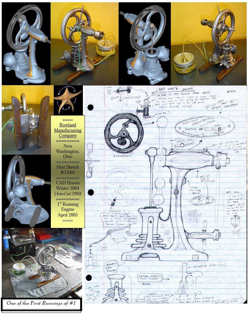
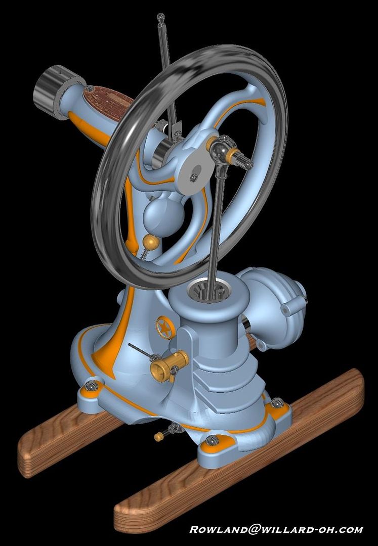
 25215 forum posts 3105 photos 1 articles | I have liked the look of the engines from RMC designed by Nick Rowland for a long time but they went through a period of being hard to get. About 18 months ago I managed to pick up a Type-A from a collector who was reducing his stash, then earlier this year I saw a link to an e-bay listing where Nick was selling a small batch of the Type-B castings. Unfortunately they were all gone but I decided to e-mail him and luckily some more were available so i snapped one up as they are on my small list of Casting sets that I would like to make. Nick's Website could probably do with an update but I'll post a link to his various designs for those interested. A couple of weeks later the box arrived and as well as the castings and individual numbered name plate it contained one of the most comprehensive drawing/construction packages you are likely to get together with a CD with several hundred images ranging from some of the original hand drawn sketches, through CAD models to patterns and mould making then machining and finally finished engines. Nick has said it is OK to share a few here, this one gives a good mix of whats on the CD
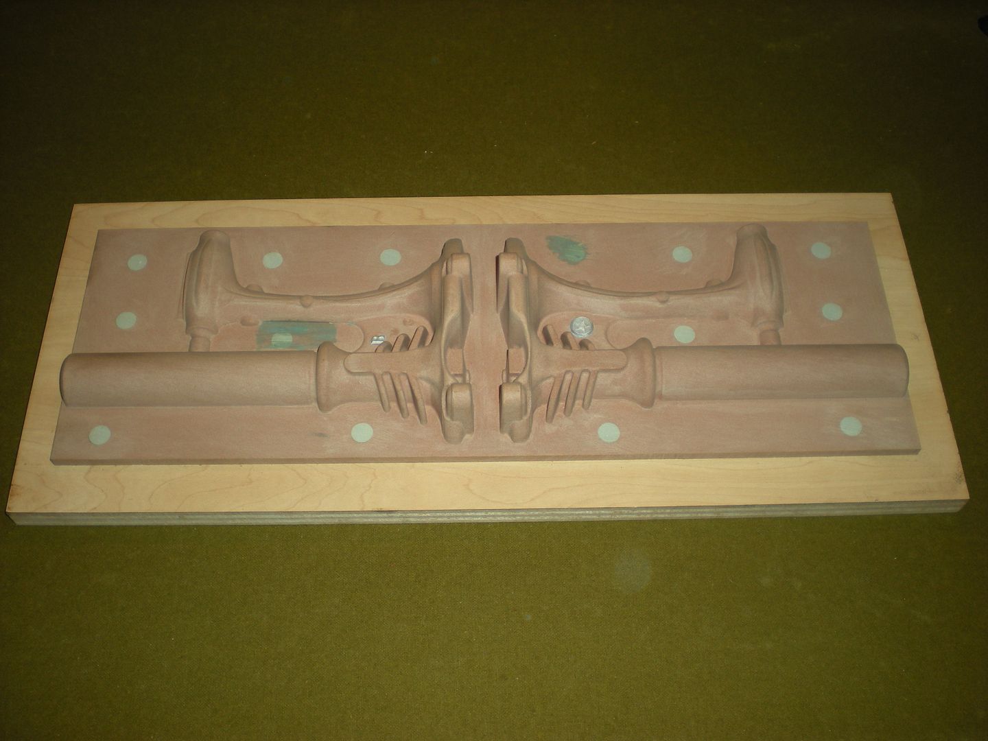
As you can't have quality castings without quality patterns these bode well for good parts. Although Nick does use traditional patterns this one looks to be done with CNC cut PU board.
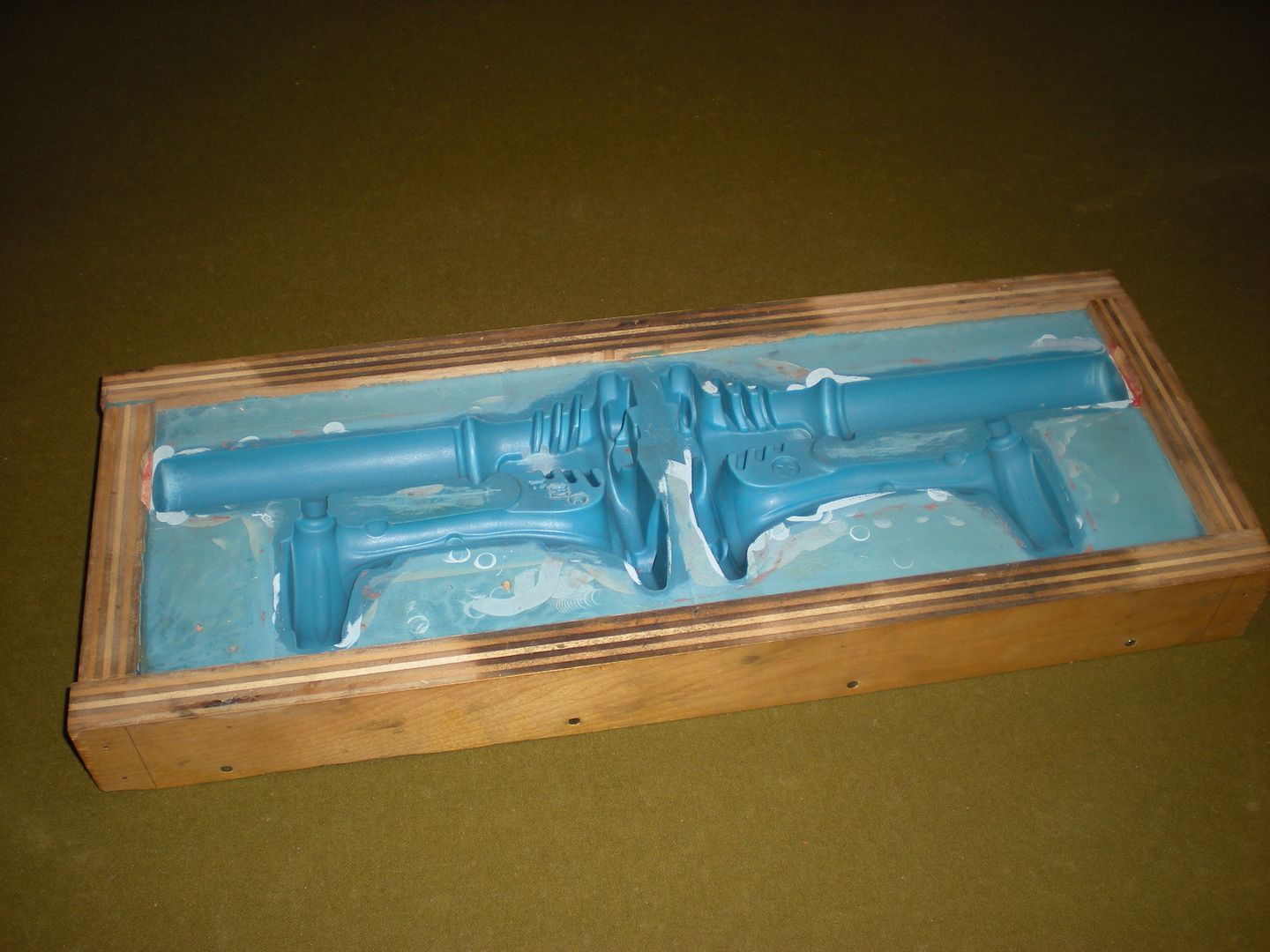
A rubber mould is then taken
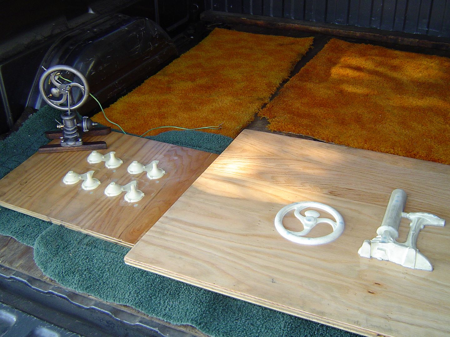
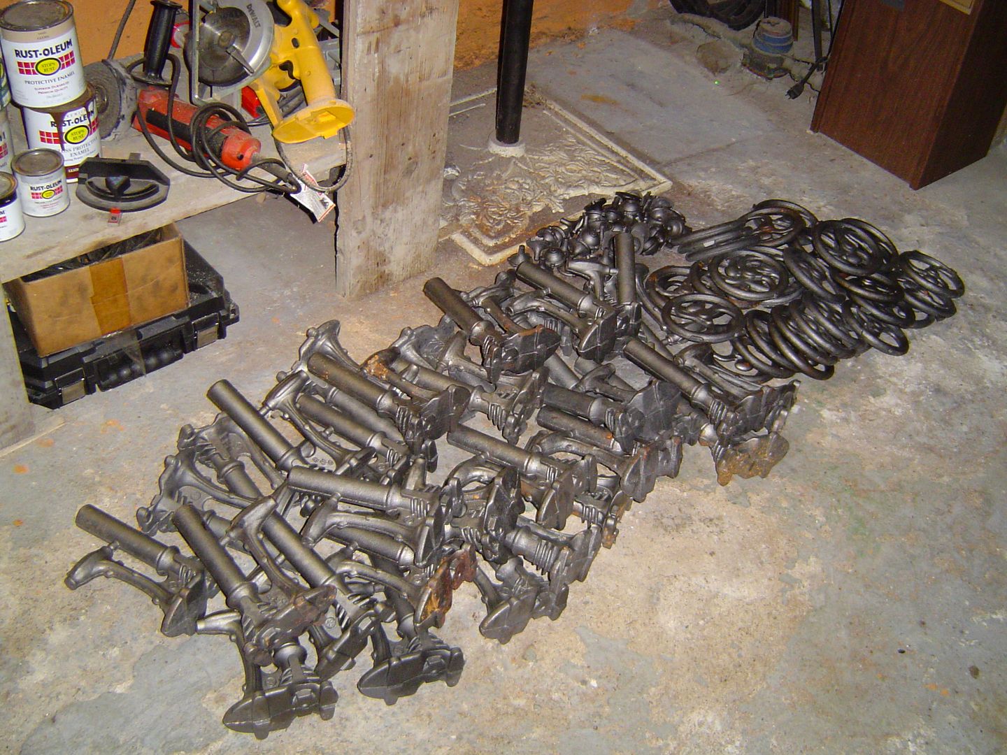
Then from that resin copies are cast and mounted onto the boards to go to the foundry
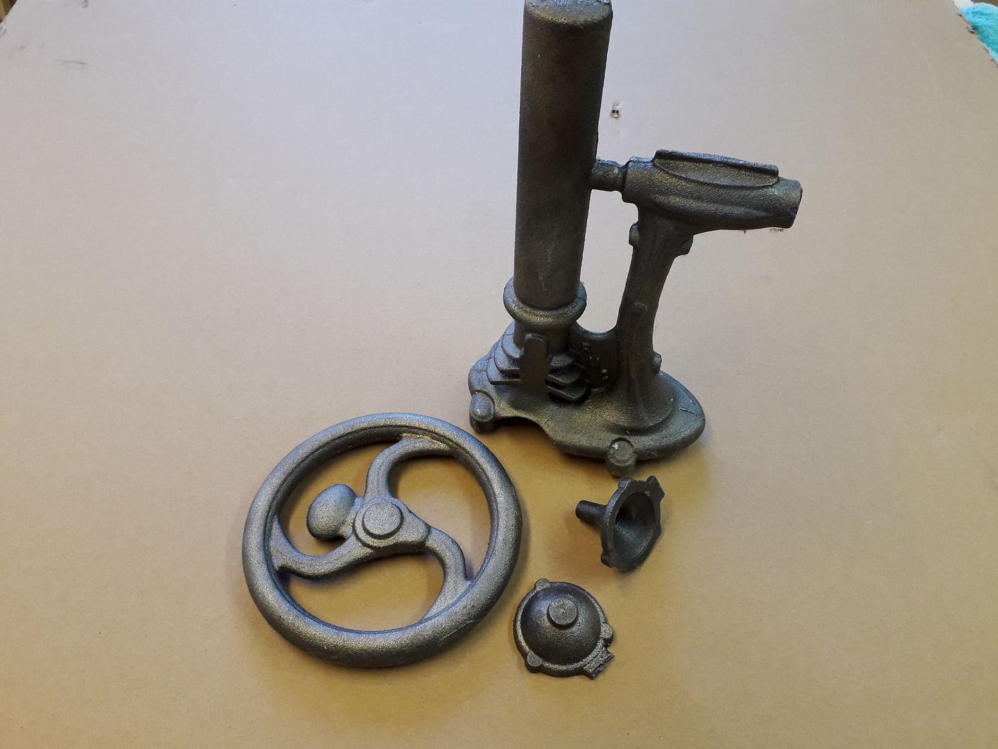
You then say the magic words and hand over some cash and come away with a few castings!
Though this is all you get when buying the quite reasonably priced set of castings, in next post I'll make a start on them and see how that very generous chucking spigot is used to hold the casting for machining
Edited By JasonB on 15/12/2019 07:49:08 |
| Ron Laden | 15/12/2019 08:13:58 |
 2320 forum posts 452 photos | I,ve said before Jason they certainly are different and it sounds as if the drawings/construction package and CD is more than one could wish for. When you say you have the type A is it a finished engine from the collector or is it a casting set, it looks interesting. |
| JasonB | 15/12/2019 10:12:29 |
25215 forum posts 3105 photos 1 articles | I got it as a casting set, I have made it but not got it to run. Swapping a few e-mails wtih Nck Roland and it was designed to run on the original MAPP gas but as that is not made any more hard to get going as a flame ignition engine on anything else as the alternatives don't have much Hydrogen in them. I have tried camping gas and will give it a go on propane, if that does not work then will more than likely convert to 4-stroke and run on Colemans fuel, propane with a hot tube would be nice but it's quite a small bore to fit everything into the cylinder head. The drawings do have a couple of general arrangement drawings of a 4-stroke layout but I may try something a bit different. Watch this |
| Ron Laden | 16/12/2019 08:12:53 |
2320 forum posts 452 photos | I cant remember Jason, did you mention previously that you have the kit for the D type engine, I think the D looks superb. p.s., watching the videos it looks to be a really good runner with decent power as well. Edited By Ron Laden on 16/12/2019 08:24:16 |
| JasonB | 16/12/2019 10:05:41 |
25215 forum posts 3105 photos 1 articles | Yes, the D castings arrived a weeks or so ago. also asked him to put my down for a type E when available and also drawings for the SB2c |
| Ron Laden | 17/12/2019 07:17:40 |
2320 forum posts 452 photos | Have you any images of the type E Jason, I cant see it one the website unless I missed it. |
| fizzy | 17/12/2019 07:24:10 |
 1860 forum posts 121 photos | Jason.....ive worked with quite a few gas variants with our burners and for off the shelf reliability the Coleman extreme is about asa good as it gets **LINK** |
| JasonB | 17/12/2019 07:27:31 |
25215 forum posts 3105 photos 1 articles | It can be done as a vertical or horizontal |
| JasonB | 17/12/2019 07:33:49 |
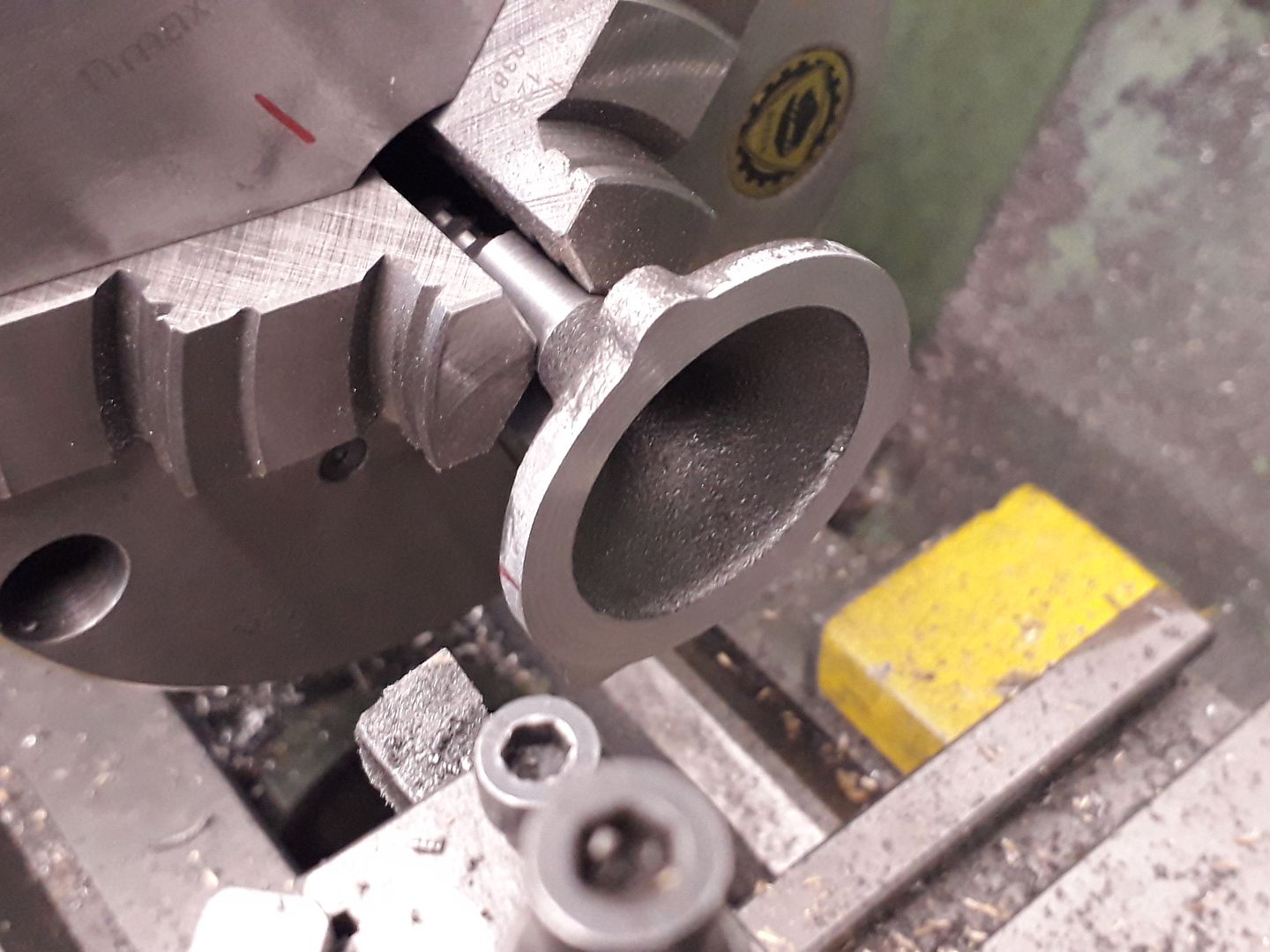
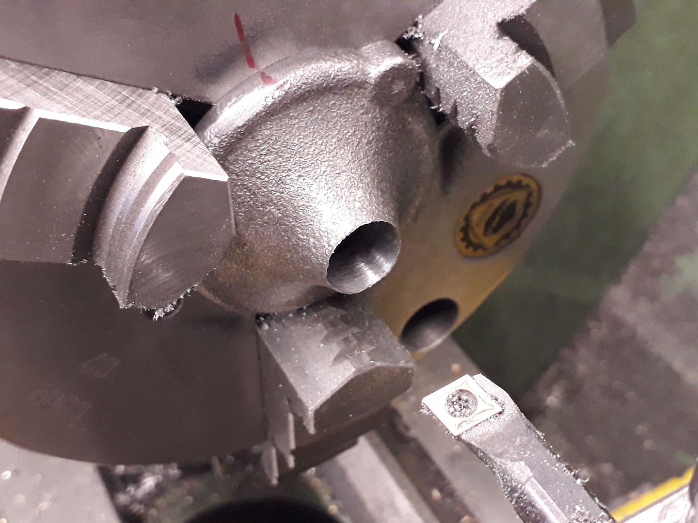
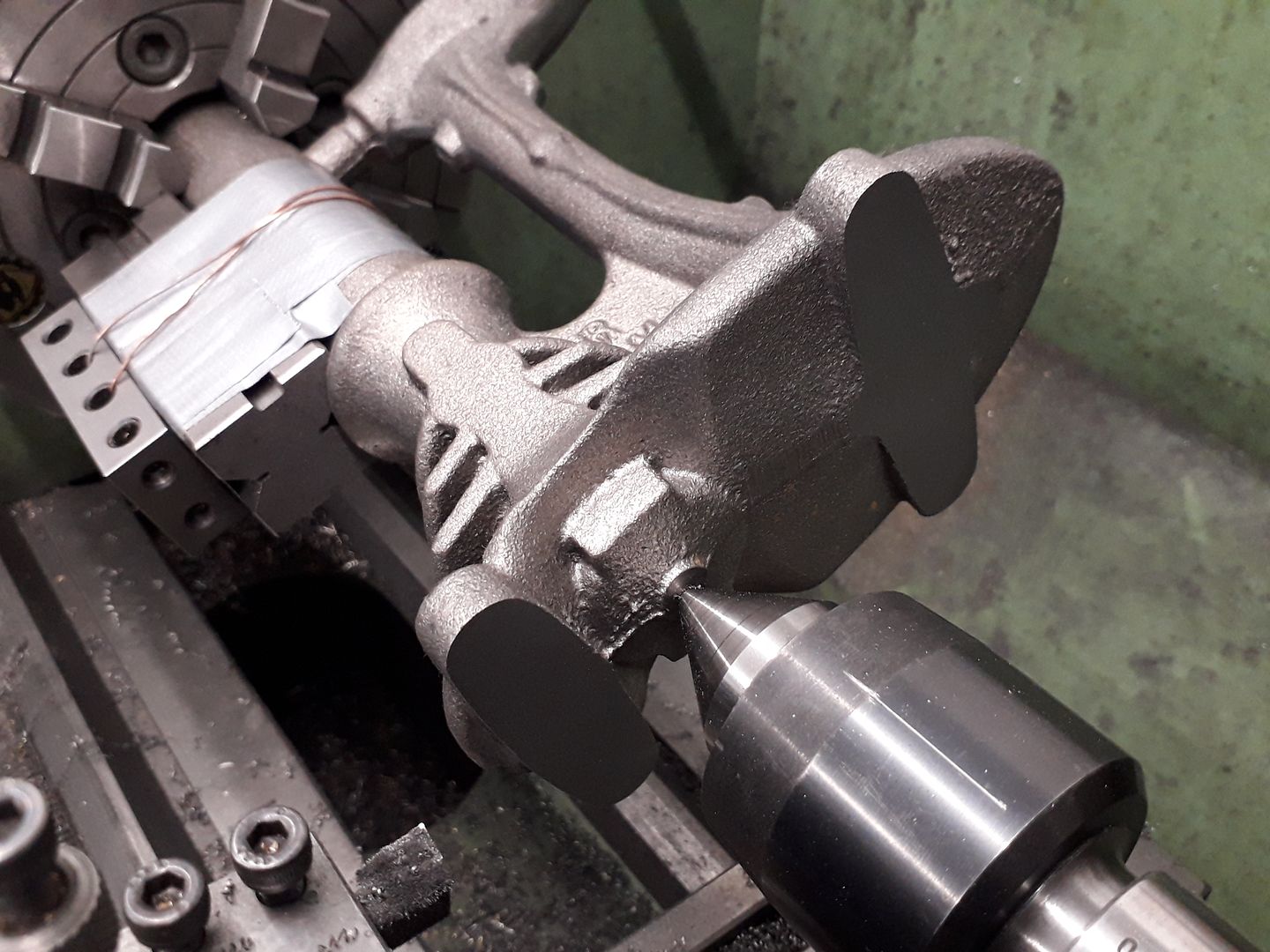
25215 forum posts 3105 photos 1 articles | I often seem to start an engine by working on the silencer (muffler) and this was no exception, I think it is because they are reasonably simple parts and can be fitted in while the previous engine is being test run or painted. I started with the half that goes towards the engine first holding by the edge of the flange to true up the chucking spigot, in fact it ran amazingly true maybe a thou or two run out but still needed skimming to remove the draft angle. I then had a parallel surface to hold in the 3-jaw chuck to skim the flange which even though it's not much more than 1/8" think machined easily - no chilled thin sections here.
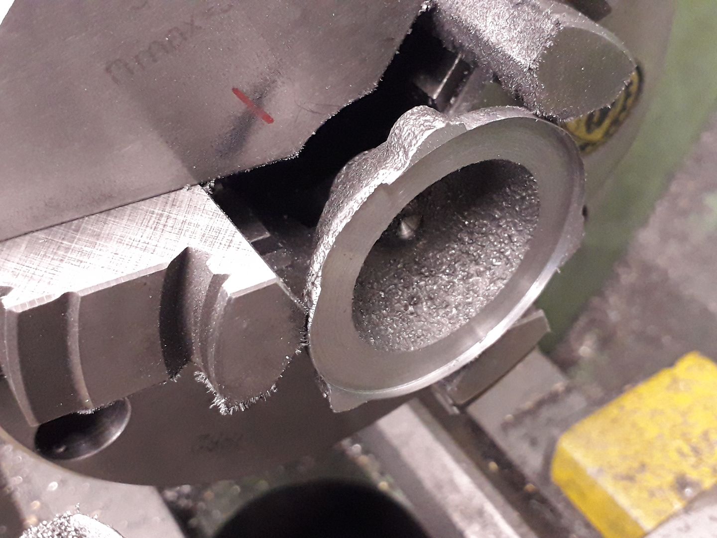
The casting was then turned around and held by the flange again, I had added the Sharpie marks when doing the spigot so it could be replaced in the same position. The spigot was cut off and a hole drilled and then bored to a firm fit on some 1/2" steel rod.
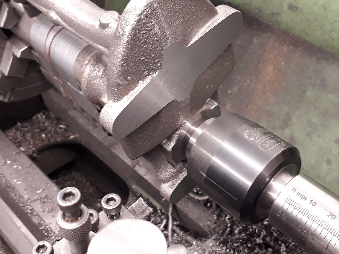
The other half was then skimmed across the flange before reducing the thickness to leave the three bosses full depth which act to space the two halves apart unlike a lot of silencers that have simple turned spacers. I cut until the edge was just breaking through as any more would have risked cutting into the chuck jaws, what little remained was easily files off.
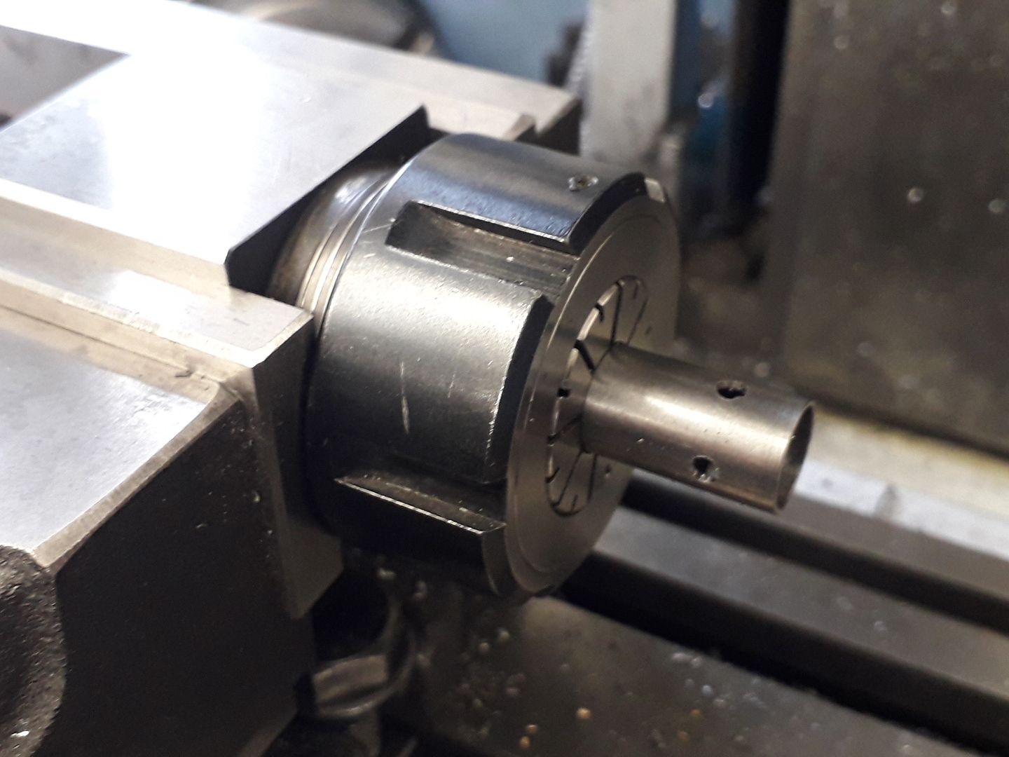
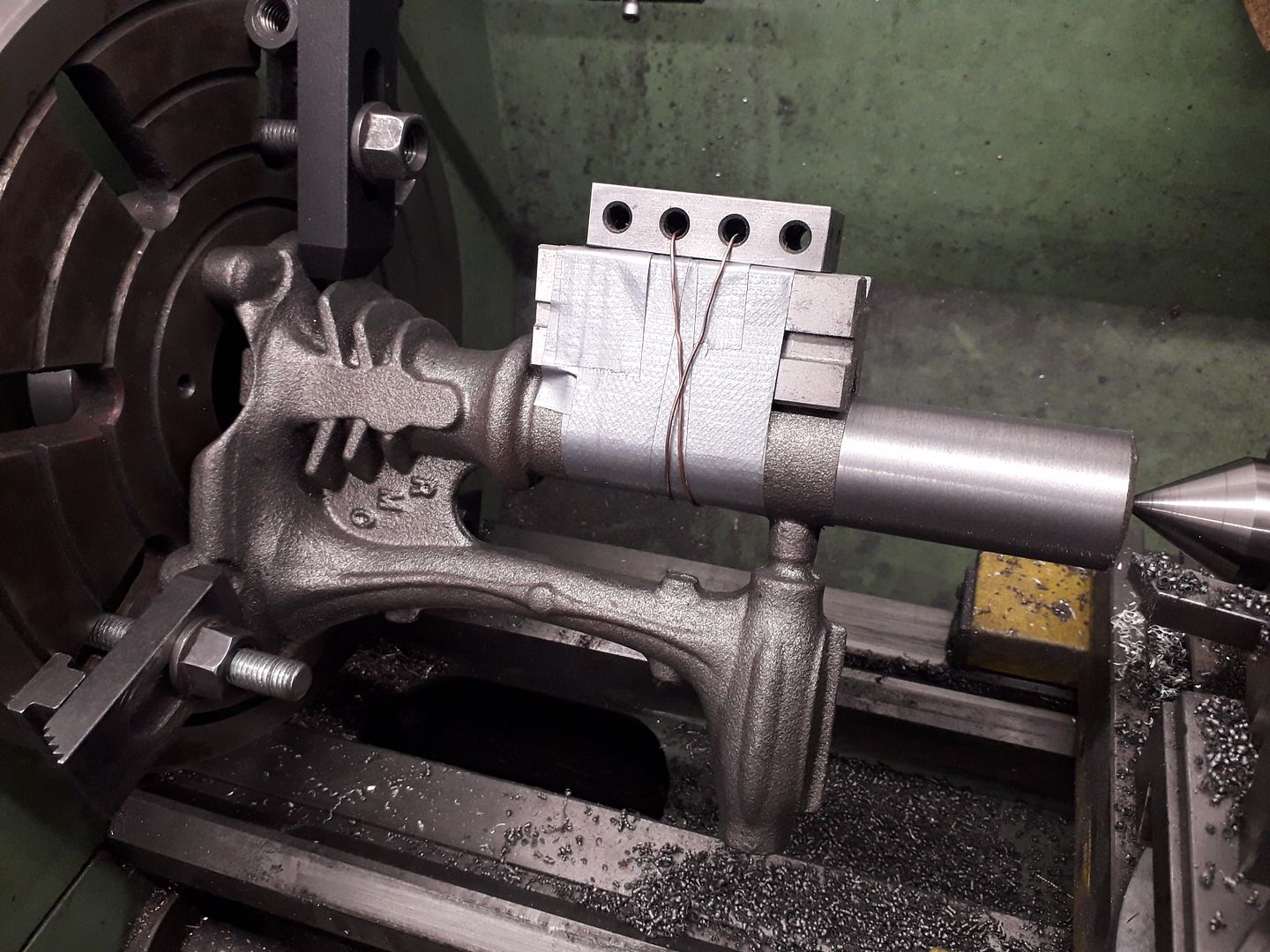
The small stub pipe is simply a piece of 1/2" steel drilled out and then cross drilled for some additional holes, I just used a square ER collet block to index the 4 holes with the back of the nut against the vice jaws to locate the block in the X-axis.
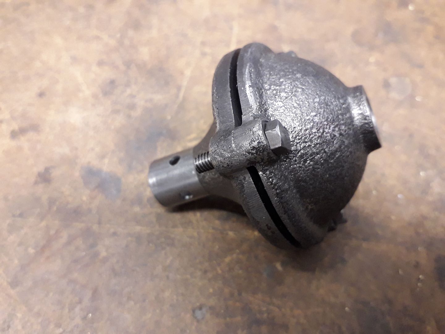
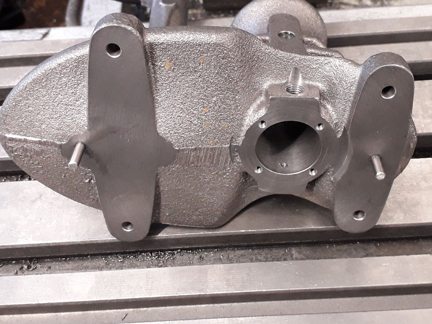
All that is left is to drill clearance holes in one half and tap the other, I opted to use BA fixings on this engine rather than UN so in this case 4BA rather than #6-32, the hex head fixings are temporary and I will turn up some fillister heads screws for the finished engine. The pipe is retained with high temp Loctite 648.
|
| Brian H | 17/12/2019 07:46:04 |
 2312 forum posts 112 photos | Thanks Jason, that looks like another nice engine. I must admit that I find the term 'gas engine' a bit confusing because my first job involved building gas engines at a company that started life as"The Premier Gas Engine Company". The gas in question was town gas, also known as coal gas and there was also producer gas made in special units for use in areas where coal gas was not available, It took me a long time to realise that the American 'gas engine' was actually a gasoline (petrol to we English) engine. Brian Edited By Brian H on 17/12/2019 08:06:57 |
| JasonB | 17/12/2019 07:48:33 |
25215 forum posts 3105 photos 1 articles | Thank's Fizzy but Nick the designer says that the camping type mixes won't work, it is not just the flame but more importantly the percentage of hydrogen that made the old MAPP the best option unless you want to get into mixing your own illuminating gas. He has said that the replacement MAP Pro can work and even Propane but they are a lot harder to get the engine running on these. Being a non compression engine it is hard to get other gasses to ignite. I'm going to give them both a try over christmas and if no luck look at the 4-stroke option. Nick is working on a new version of that engine that will run on the available gasses but it won't be for a while as he will also need to rework the patterns and alter drawings as although very good CAD has moved on a lot since 2005 when the engine was available. |
| Ron Laden | 17/12/2019 08:17:18 |
2320 forum posts 452 photos | Wow, the top speed of the type E is amazing, didnt expect that from these type of engines. |
| JasonB | 17/12/2019 10:04:13 |
25215 forum posts 3105 photos 1 articles | Should be able to get close to that when I have this one running right. |
| JasonB | 22/12/2019 19:08:52 |
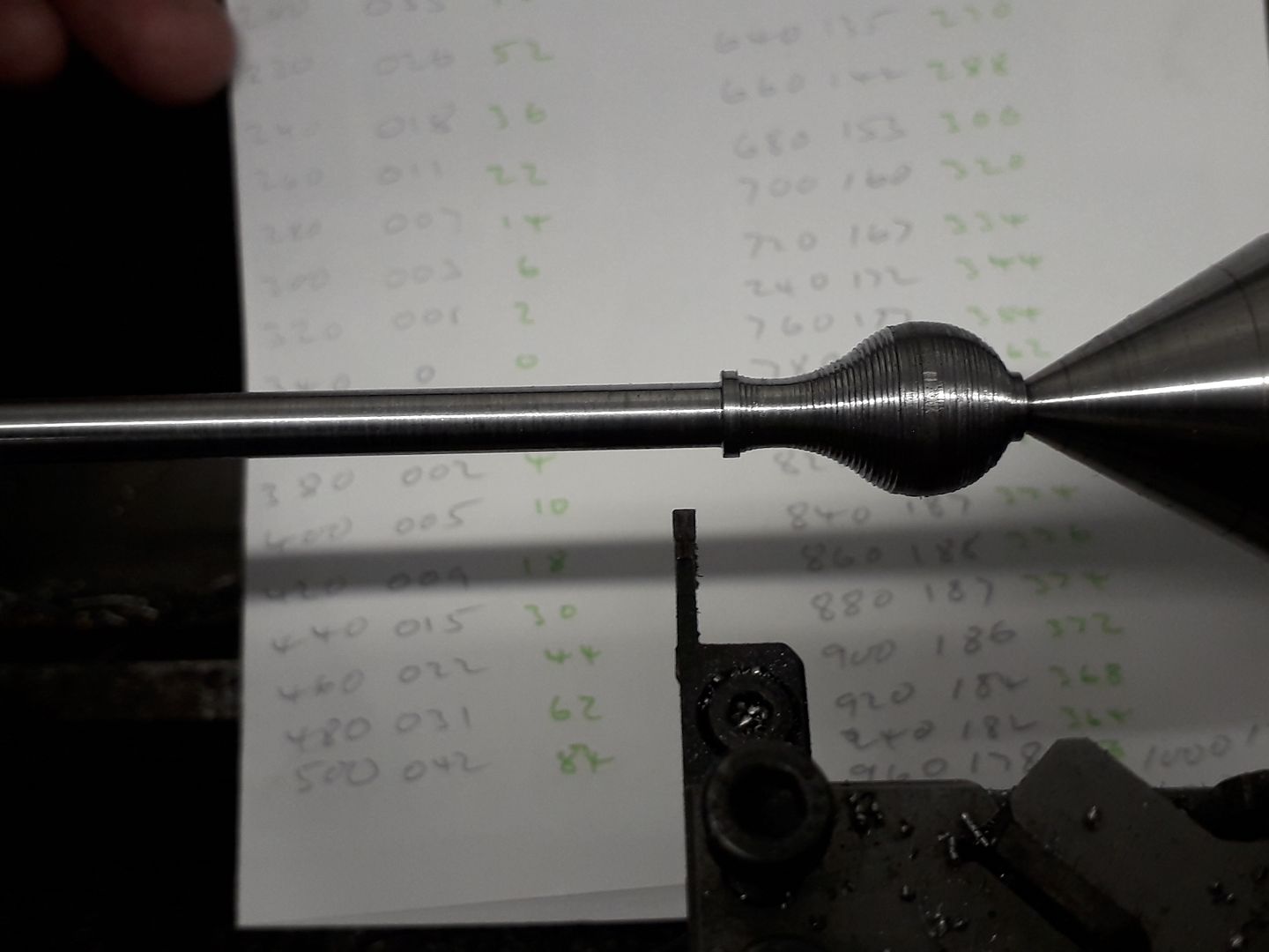
25215 forum posts 3105 photos 1 articles | Taking a break from the castings I thought I would do the conrod next, this was roughed out from a piece of 5/8" steel. To produce the shapely big end I drew it out in Alibre and used that to produce a series of co-ordinates at 0.020" spacing which were cut with an insert parting tool
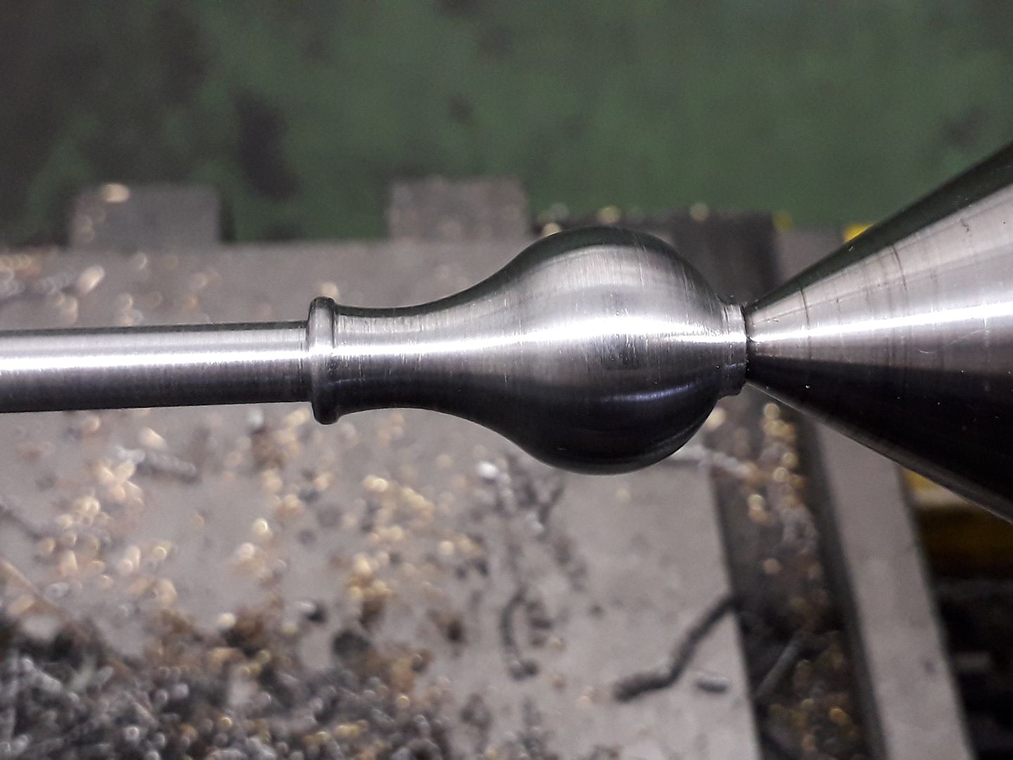
The stepped cut was then blended with files until a pleasing shape was produced.
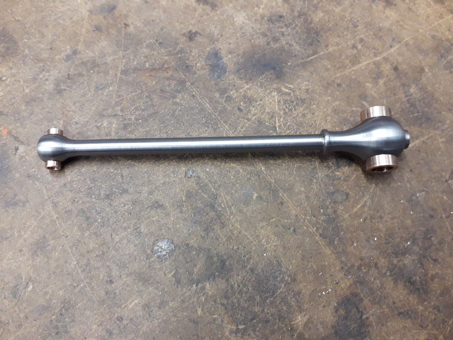
As the distance between big and little ends was less than the width of my vice jaws I used a couple of 15-30-60 blocks as packing to hold the rod for drilling and reaming the ends, I also supported the big end with a make shift jack from some clamping nuts and a stud to make sure it did not deflect.
A couple of bronze bearings were turned up and fixed with 648 Loctite and the drilling for the oiler in teh big end carried through the bearing.
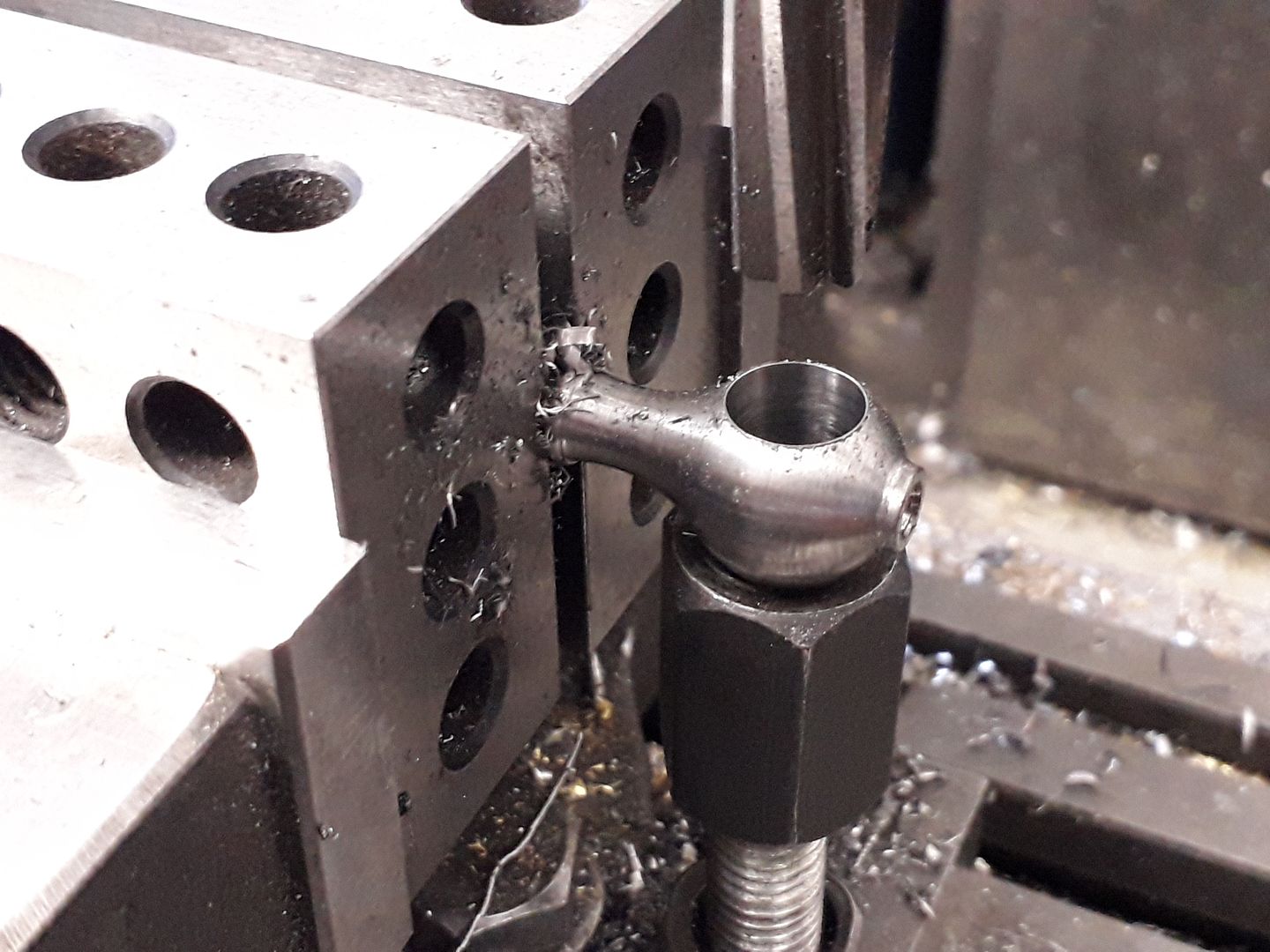
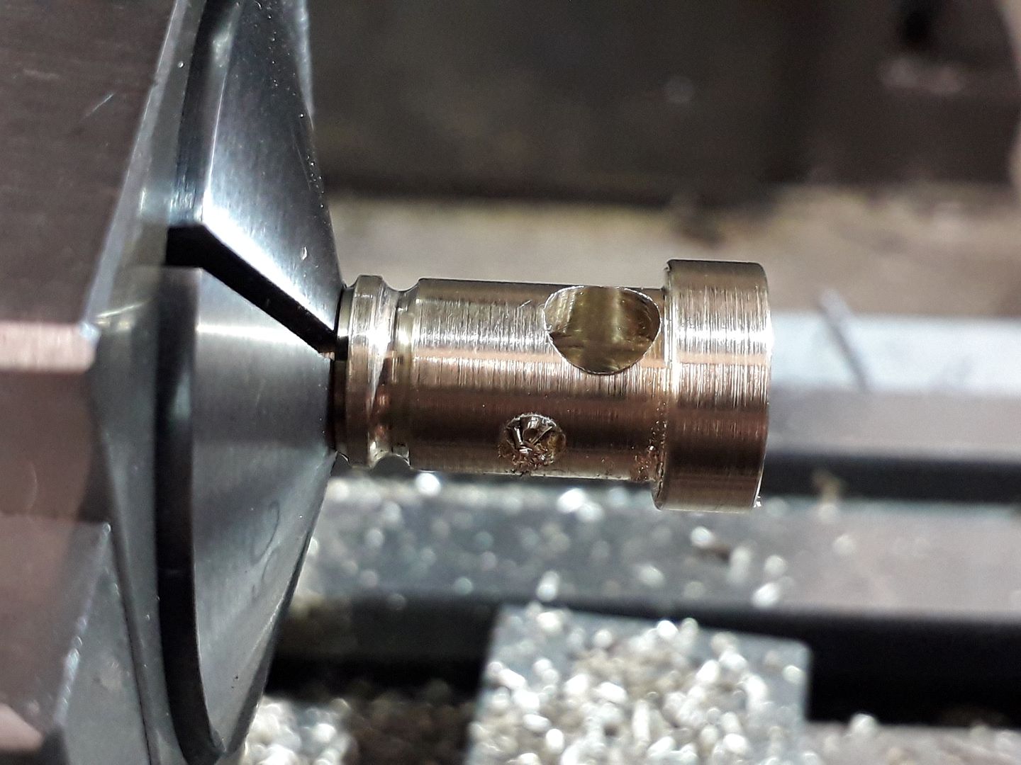
The carb is a fairly simple turning job with a few decorative beads that was then transfered to a 5C collet block to drill the cross hole for the choke and one half way in at 90deg for the fuel line nipple. I must stop taking such close up shots as it make sthe surface look rough!
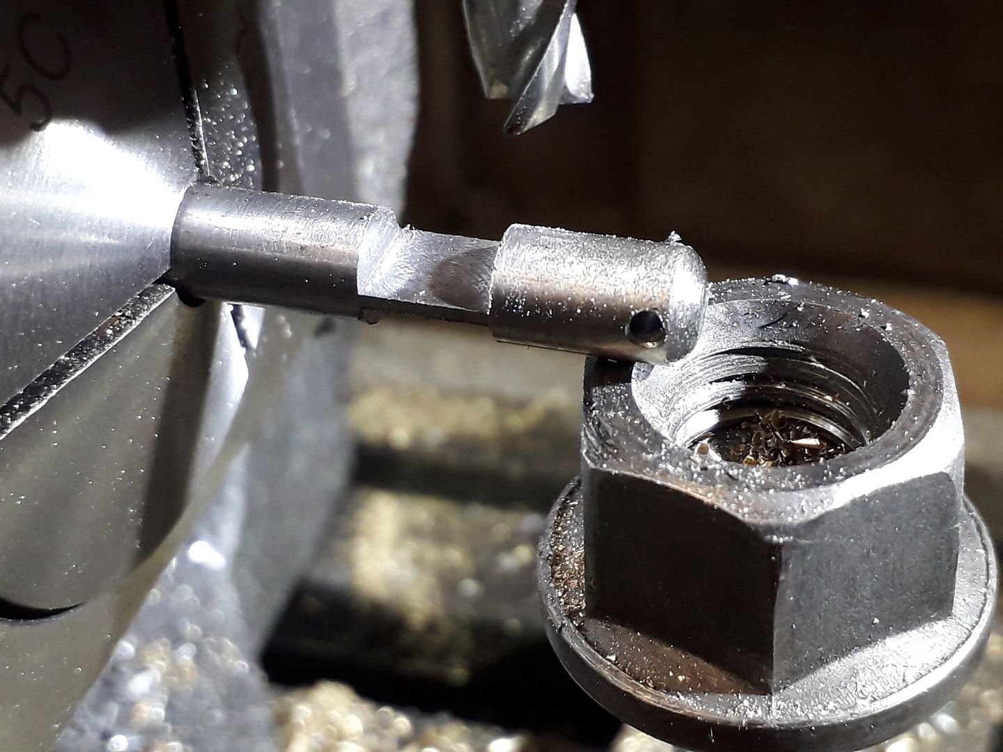
The choke is just a spindle with a hole for the control lever at the end and then milled away either side to form a butterfly, not much metal left so a jack was used again.
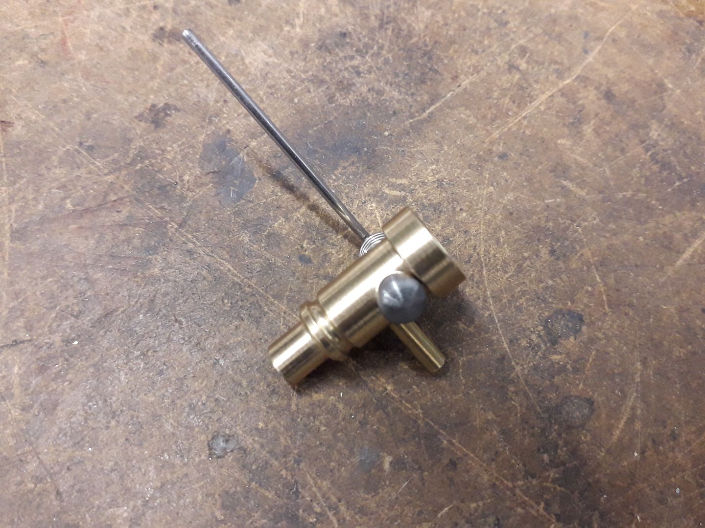
The completed carb which looks a lot better from this distance, it's just a press fit into the hole in the cylinder side.
J |
| Ron Laden | 23/12/2019 07:09:11 |
2320 forum posts 452 photos | The great thing about your threads Jason is you showing the set up in making the parts I for one have learnt such a lot from them. Making the conrod is a good example and the end result excellent.
|
| JasonB | 26/12/2019 19:10:01 |
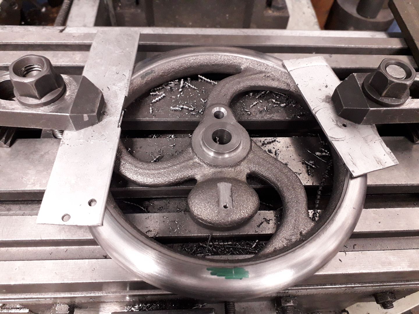
25215 forum posts 3105 photos 1 articles | Thank's Ron good to know someone is finding it useful. I was just able to fit the jaws of the 3-jaw chuck between the spokes and counter weight of the flywheel casting which ran reasonably true and this enabled me to work on both sides and the edge all at once. The curved finished surface extends around about 220 degrees around the rim before stepping in slightly to the rest of the cast surface. I started by just taking off enough from front, back and edge to get a cleaned up ring and then measured the width. Armed with this size I worked out co-ordinates and machined the rim in 20 thou steps before blending these together with graver, files and finally some Emery.
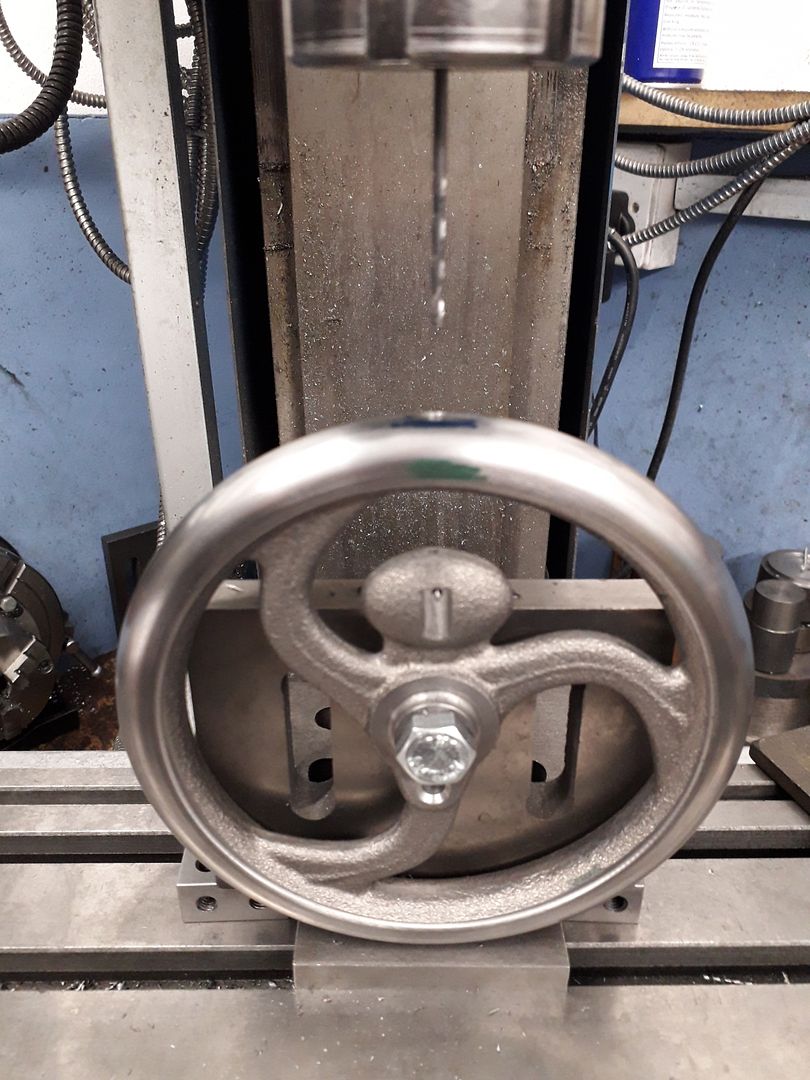
I also took a light cut to define where the machined surface meets the cast and later blended that in with the Dremel. Hub was also machined and hole drilled and finish bored to a firm push fit on the PGMS that I used for the shaft. The flywheel was then clamped to the mill table to have the crankpin hole drilled and reamed as well as a slot milled for the governor bracket and a tapped hole to hole said bracket in place. You may also just be able to see the mark on the rim to indicate where the governor pin hole needs to be drilled which was marked with a carbide point held in the mill chuck.
This mark made it easier to line things up when it came to drill the pin hole which is also counter bored and threaded so the threaded pin can be turned to alter the governor spring pressure.
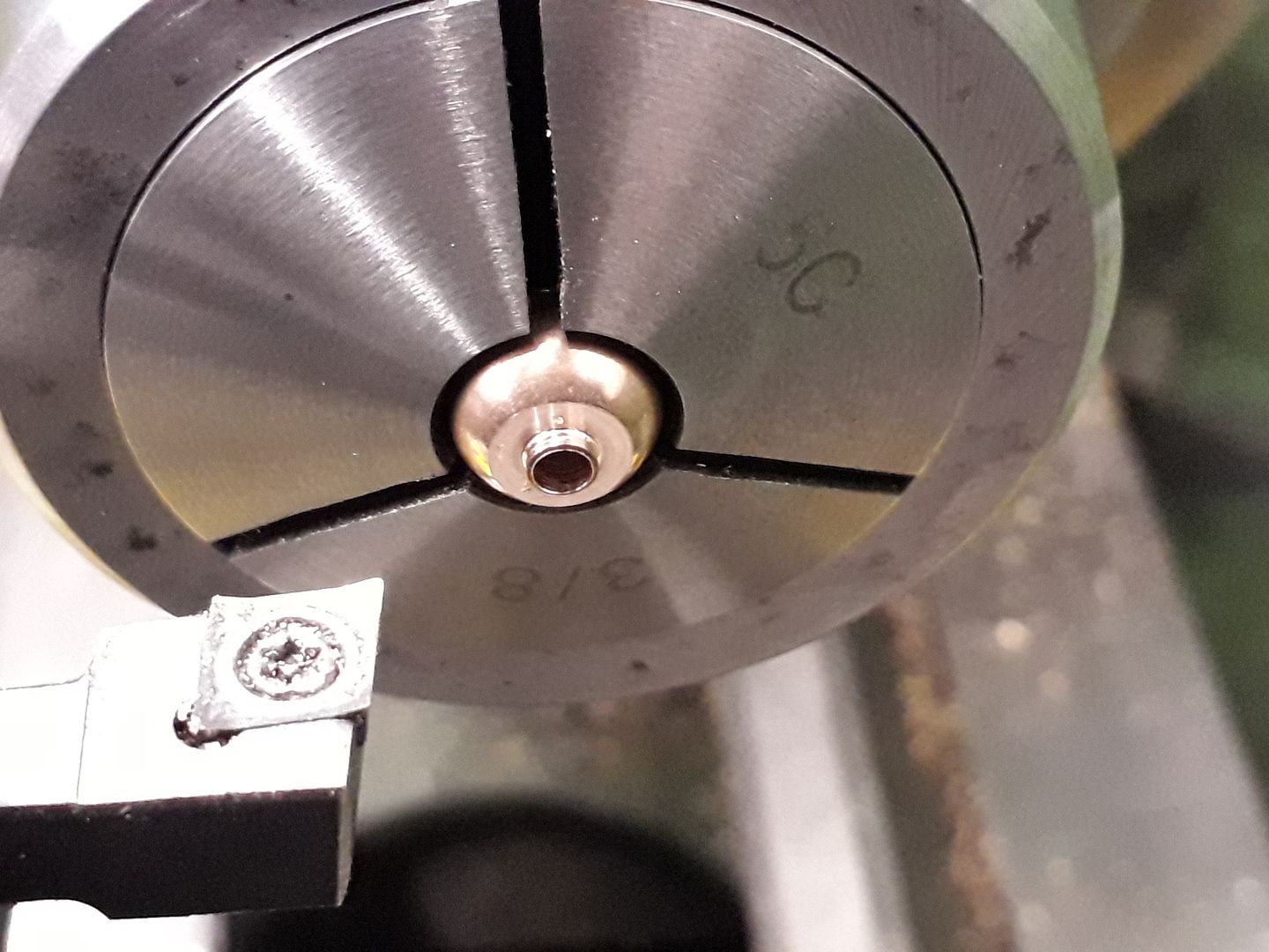
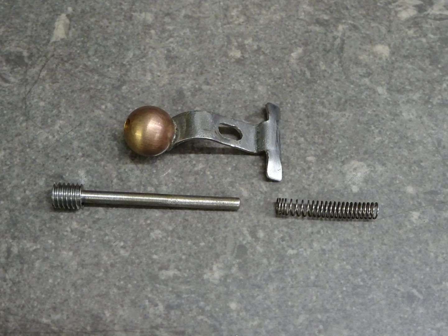
The governor weight is made by modifying a 3/8" diameter bronze ball by adding a hole and turning a small shoulder.
The shoulder is used to locate the ball in the governor bracket while it is soldered in place. In use when running as in hit and miss mode the ball and bracket are thrown out by the force of the rotating flywheel which causes it to move away from the isolated ignition contact so the engine will miss, as things slow back down the bracket will again come into contact with the isolated point and it will hit (fire). governed speed can be adjusted by screwing the long pin in and out which alters the spring tension. To run as a throttler the nut retaining the bracket is simply tightened so it can't move outwards.
J |
| Ron Laden | 27/12/2019 06:44:28 |
2320 forum posts 452 photos | Some nice work Jason, easy to overlook small parts but I bet the governor bracket took a bit of making looking at the shape of it. I had to look up graver files, never heard that term before. |
| JasonB | 27/12/2019 07:10:19 |
25215 forum posts 3105 photos 1 articles | A graver is a hand held turning tool often used for small work but I actuually use a couple of woodworking "scrapers" for this sort of thing. The bulk of the filing was done with one of the Tome Long Angle Lathe files that ARC sell which shift a lot more metal than a standard file, would be nice if they did a smaller size say 6" long. This is the fine swarf that it takes off, in this case from a similar size and shape steel part.
Edited By JasonB on 27/12/2019 07:10:33 |
| Ron Laden | 27/12/2019 07:21:49 |
2320 forum posts 452 photos | Thanks Jason will have to get myself one of the long angle files. |
| JasonB | 28/12/2019 20:20:18 |
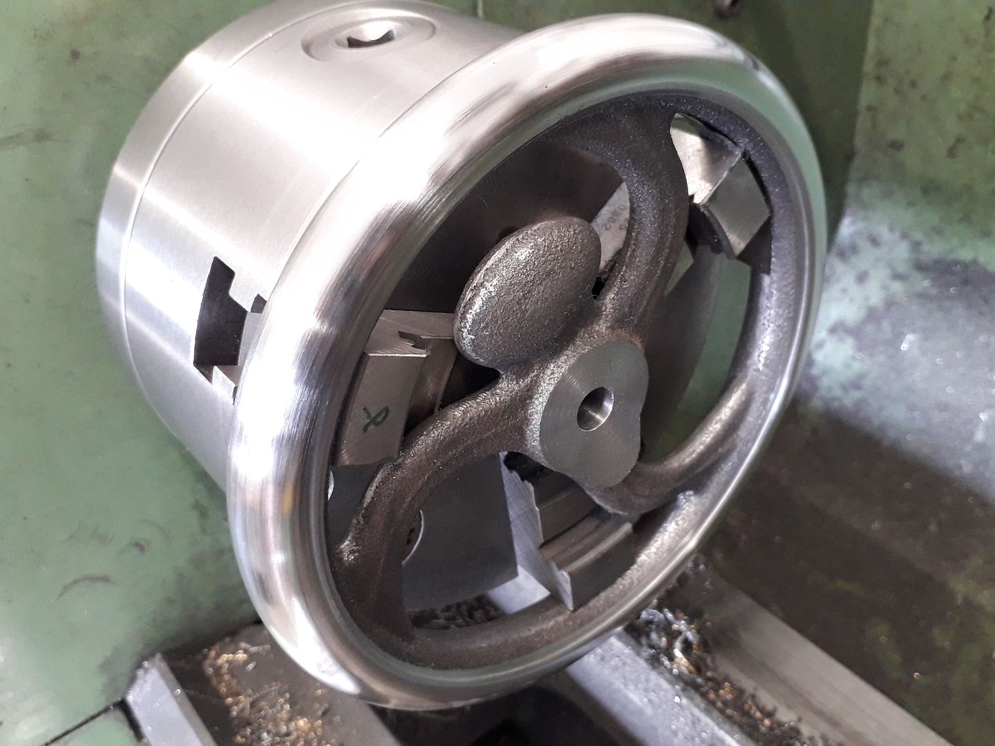
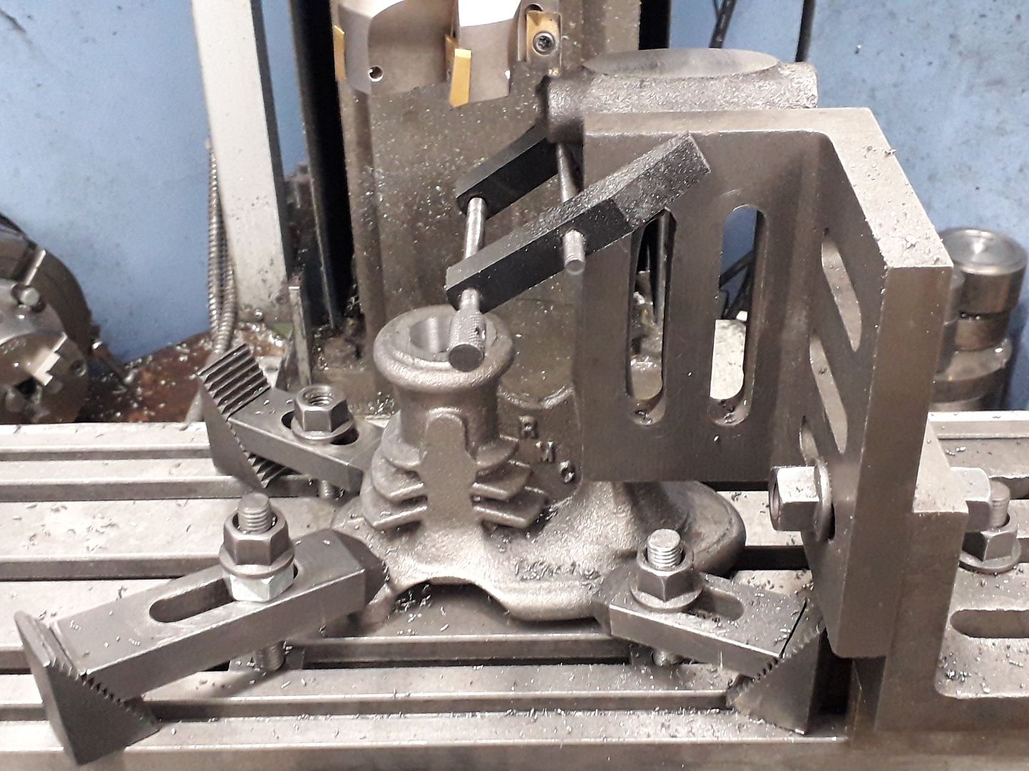
25215 forum posts 3105 photos 1 articles | Those that take MEW will have seen most of these photos although text is different, I'll post it here anyway so the whole engine build is covered. The main bed casting looks quite a challenge at first but each operation is listed out in the build instructions and was actually not too hard to do. First item is to hold in the 4-jaw by the chucking spigot and turn the small pip on the end flat and drill a ctr hole. I added some balance weights in the form of a couple of vee blocks and a 15-30-60 block taped and wired on which enabled me to run at about 400rpm before the lathe wanted to start dancing down the workshop. Once the tailstock ctr is brought up for additional support the feet can be skimmed flat.
The next suggested thing is to bore the cylinder but I could sense a little bit of movement when facing the pip so did not want to do the bore like this, I think is was due to the chucking spigot being slightly larger at the far end so it could not be gripped really firmly. So I flipped the casting around and clamped it to the faceplate so that I could true up the end of the chucking spigot to give me something even to hold.
With the bore and cylinder head mating face now machined I brought up the tailstock again and took the slightest skim off the feet to make sure they were true to the completed bore as that would be my ref surface for what followed.
One advantage of the imported lathes with their flange mount is that the studs can quickly be removed from the backplate gicing a large flat area so the chuck can be clamped to the mill table which is how I held the casting to drill the holes for the feet, cylinder head and I also added two holes for 3mm dowel pins front to back as I decided not to use a machining plate and the dowels would help with lining things up.
So with two bits of 3mm drill rod in the holes resting against the side of a tee slot the casting was set up to machine the top of the bearing housing that takes the oval shaped name plate, I added an angle plate against the side to resist the force of the cutter as I did not want to bend or break the casting.
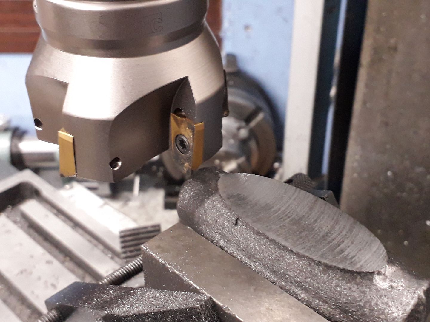
While setup like this I also cleaned up the top of the cylinder, the 80mm new indexable shell mill from ARC allowing me to get close enough without the quill hitting the overhanging bearing housing.
The instructions suggest using a 1" CSK to chamfer the top of the cylinder but as I don't have one that big I just managed with a boring head and tool ground at 45degrees.
To be continued |


Please login to post a reply.
Magazine Locator
Want the latest issue of Model Engineer or Model Engineers' Workshop? Use our magazine locator links to find your nearest stockist!
Sign up to our Newsletter
Sign up to our newsletter and get a free digital issue.
You can unsubscribe at anytime. View our privacy policy at www.mortons.co.uk/privacy
Latest Forum Posts
- *Oct 2023: FORUM MIGRATION TIMELINE*
05/10/2023 07:57:11 - Making ER11 collet chuck
05/10/2023 07:56:24 - What did you do today? 2023
05/10/2023 07:25:01 - Orrery
05/10/2023 06:00:41 - Wera hand-tools
05/10/2023 05:47:07 - New member
05/10/2023 04:40:11 - Problems with external pot on at1 vfd
05/10/2023 00:06:32 - Drain plug
04/10/2023 23:36:17 - digi phase converter for 10 machines.....
04/10/2023 23:13:48 - Winter Storage Of Locomotives
04/10/2023 21:02:11 - More Latest Posts...
- View All Topics
Support Our Partners


Shopping Partners
Subscription Offer

Latest "For Sale" Ads
- Reeves** - Rebuilt Royal Scot by Martin Evans
by John Broughton
£300.00 - BRITANNIA 5" GAUGE James Perrier
by Jon Seabright 1
£2,500.00 - Drill Grinder - for restoration
by Nigel Graham 2
£0.00 - WARCO WM18 MILLING MACHINE
by Alex Chudley
£1,200.00 - MYFORD SUPER 7 LATHE
by Alex Chudley
£2,000.00 - More "For Sale" Ads...
Latest "Wanted" Ads
- D1-3 backplate
by Michael Horley
Price Not Specified - fixed steady for a Colchester bantam mark1 800
by George Jervis
Price Not Specified - lbsc pansy
by JACK SIDEBOTHAM
Price Not Specified - Pratt Burnerd multifit chuck key.
by Tim Riome
Price Not Specified - BANDSAW BLADE WELDER
by HUGH
Price Not Specified - More "Wanted" Ads...
Get In Touch!
Do you want to contact the Model Engineer and Model Engineers' Workshop team?
You can contact us by phone, mail or email about the magazines including becoming a contributor, submitting reader's letters or making queries about articles. You can also get in touch about this website, advertising or other general issues.
Click THIS LINK for full contact details.
For subscription issues please see THIS LINK.
Digital Back Issues


Donate

 Register
 Log-in
Model Engineer Magazine
- Percival Marshall
- M.E. History
- LittleLEC
- M.E. Clock

ME Workshop
- An Adcock
- & Shipley
- Horizontal
- Mill

Subscribe Now
- Great savings
- Delivered to your door

Pre-order your copy!
- Delivered to your doorstep!
- Free UK delivery!
All Forum Topics > I/C Engines > RMC Type-B Engine Build