Forum sponsored by:

Little '36 Midget Build
| JasonB | 14/10/2019 18:57:09 |
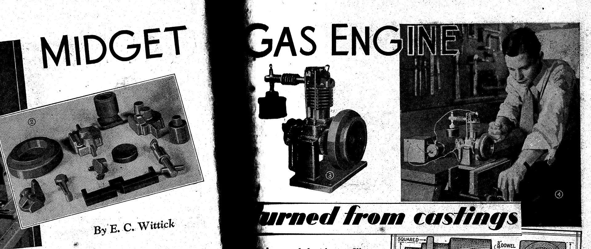
 25215 forum posts 3105 photos 1 articles | I first became aware of this engine when one popped up as a suggested video on You-tube and I quite liked the look of it. The Video said that the design was in a 1936 issue of Popular Mechanics which detailed making the patterns and a second issue had the working drawings and machining description. After a bit of googling I found the first part on the web but not the second, however the two parts were also published in Popular Mechanics "Shop Notes" from 1938 which I managed to buy an old copy of.
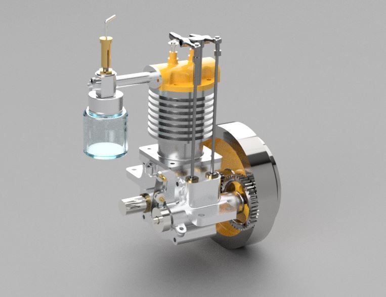
Now you know how I feel about some castings and that combined with a newly acquired CNC mill made the decision to cut from solid an obvious choice and while I was at it a reduction in size from the original 1 1/4" bore down to my usual 24mm bore and a complete metric design. As shown in the magazine there were some rather crude details and lack of refinement so I also set about changing just about every part yet still staying true to the original layout and the look of an old engine not a clunky barstock engine. A few evenings work in Alibre and the basic design was ready.
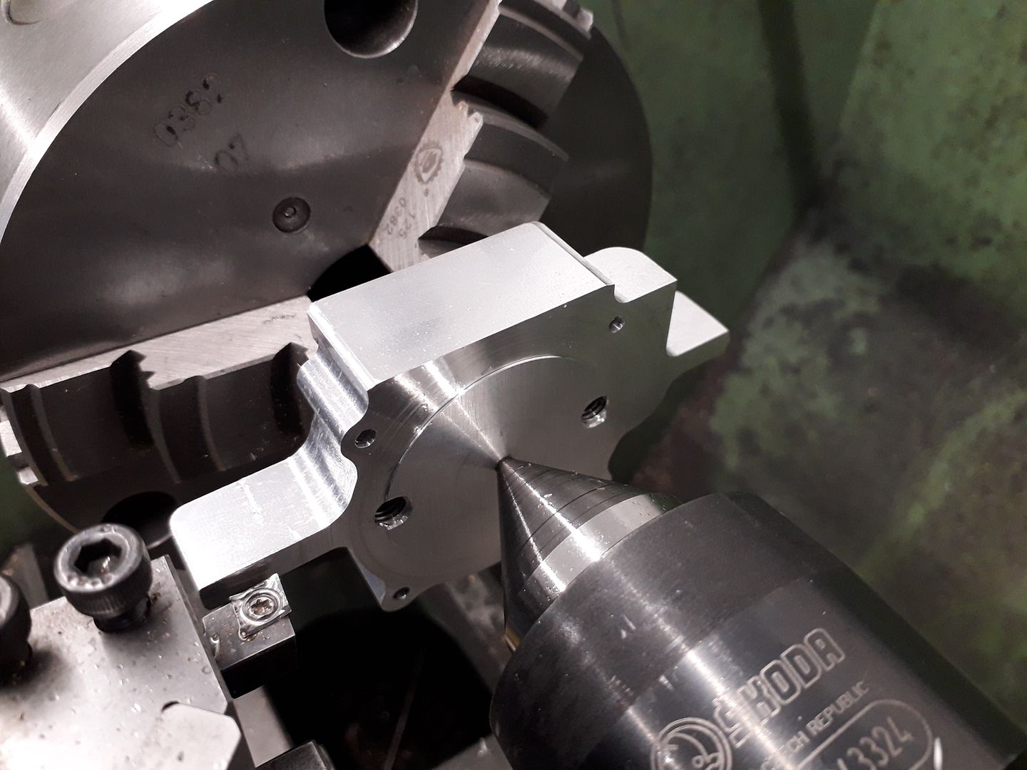
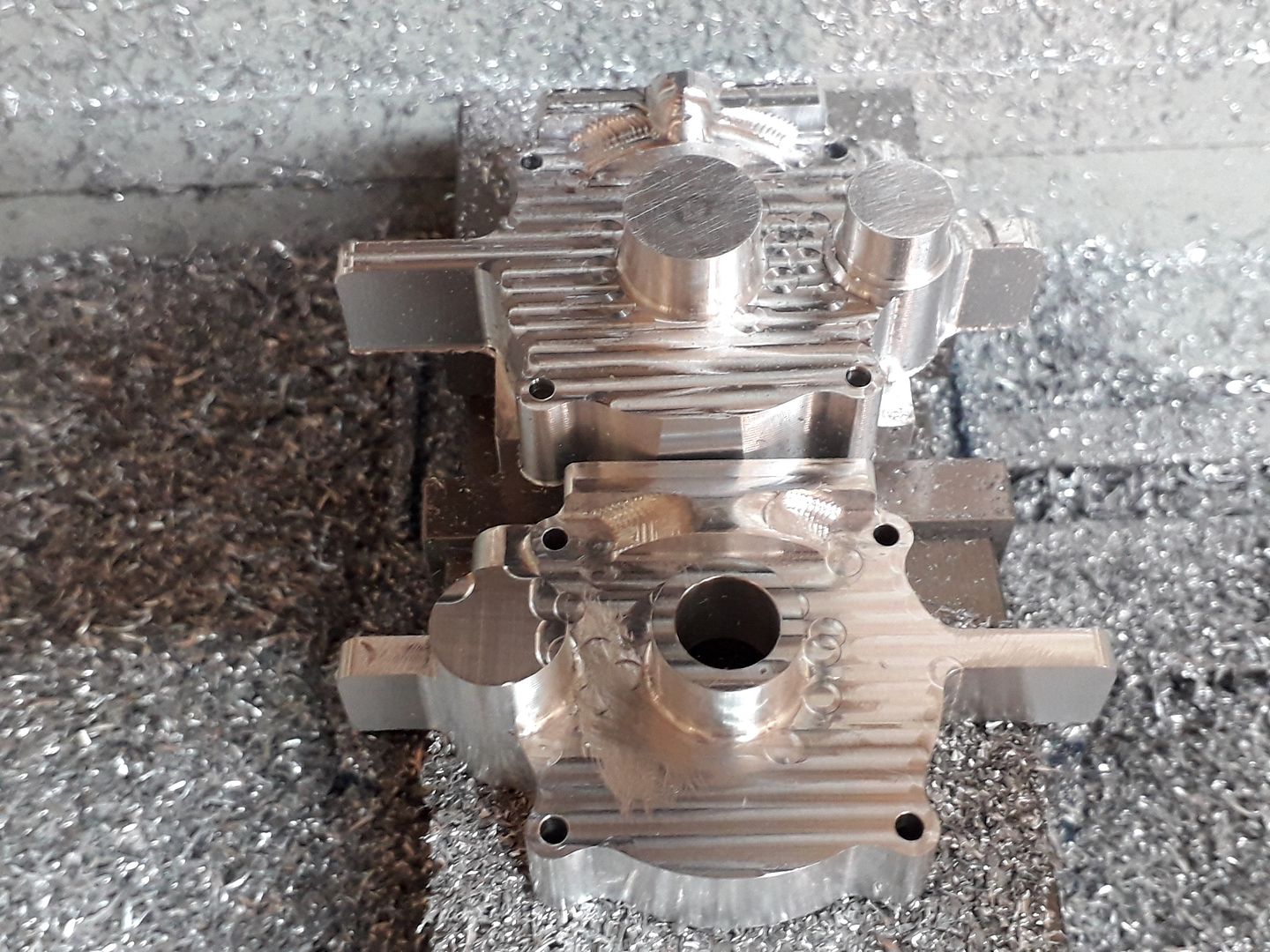
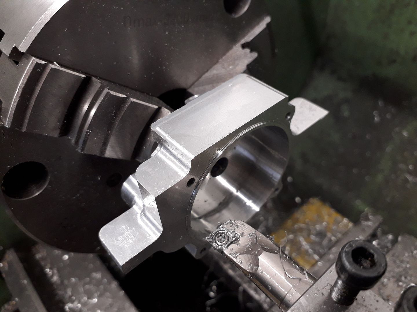
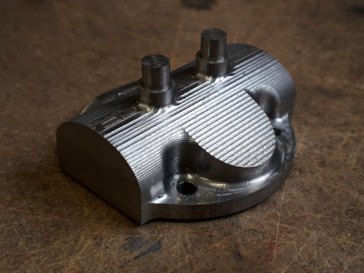
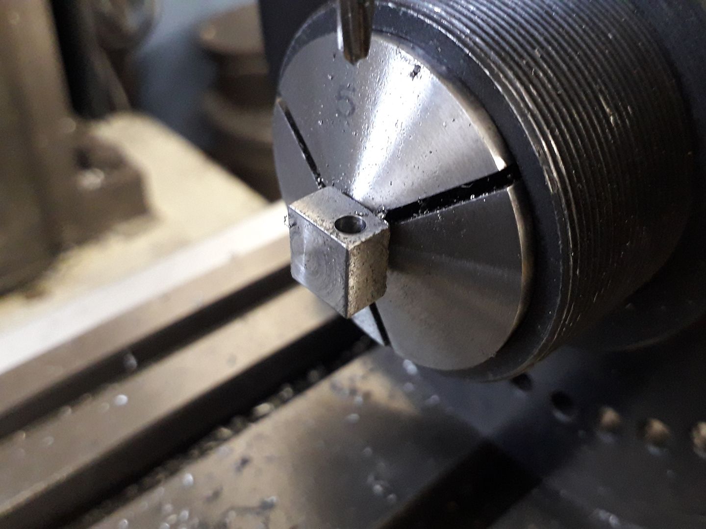
The parts that needed the most work and that would make or break the project were the two crankcase halves so I started with them by exporting my design from Alibre to F360 where I used the CAM to create the codes for cutting the crankcases. Rather than make nesting jaws to mill the inside I decided to use the lathe, firstly bringing the case down to thickness with the tailstock giving support as there was not much to hold during the interrupted cuts.
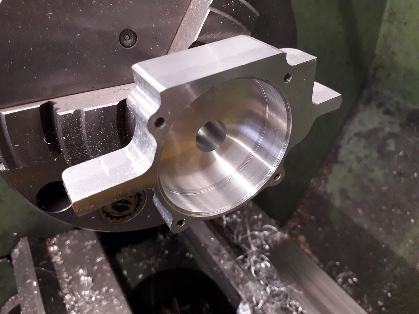
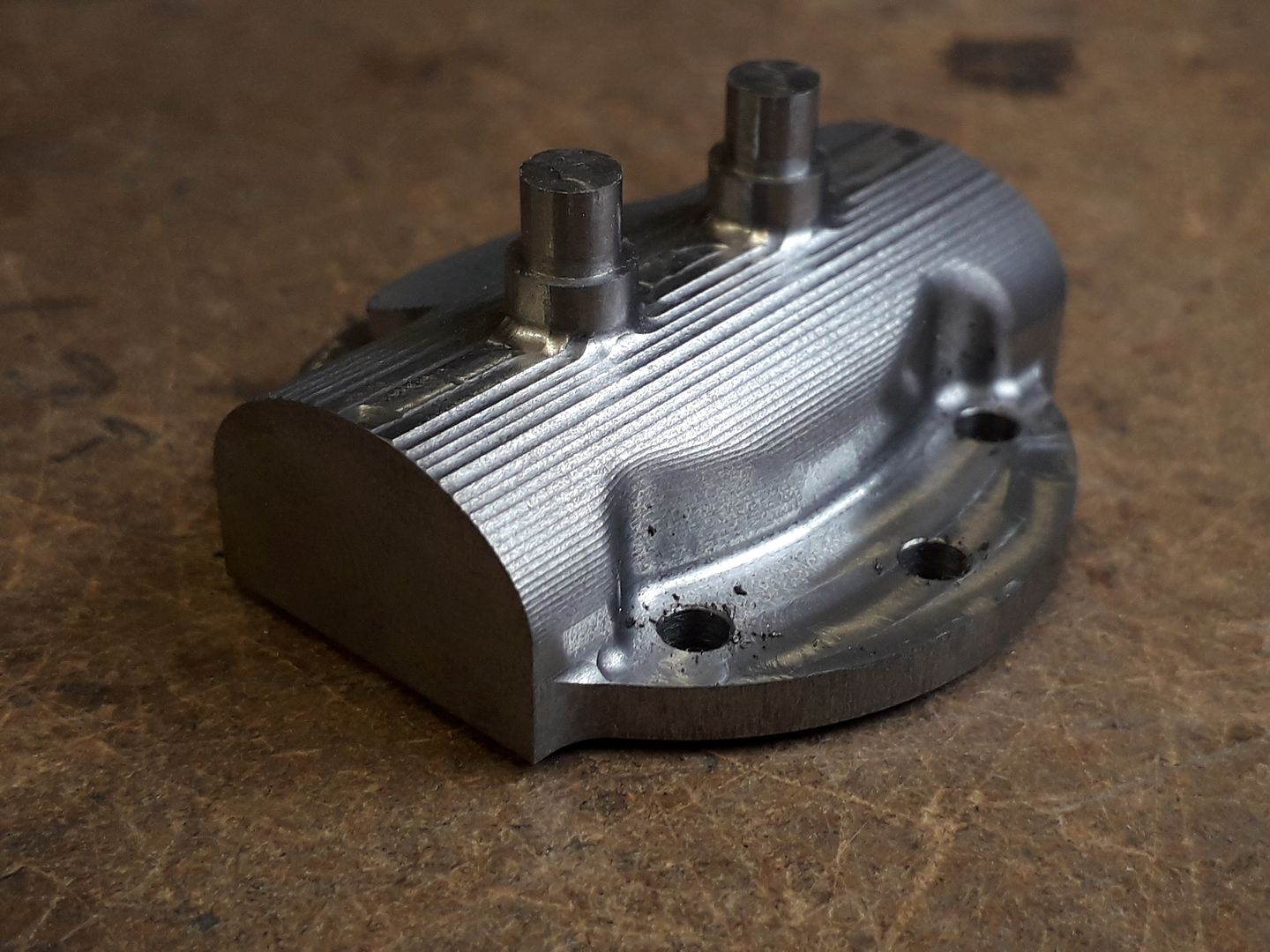
Followed by boring out the space for the crank and an undersize bearing housing. You can just see that I also included a small locating recess for a spigot on the other half, the original did not have this but I felt it would help keep the two halves lined up.
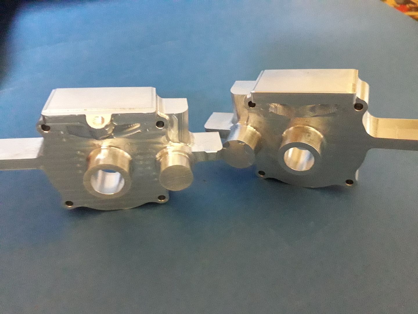
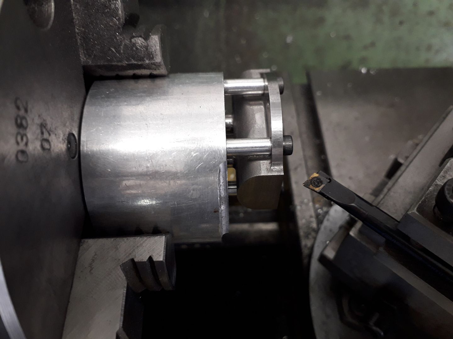
The rear half was milled out with a few changes to the CAM to take into account what I had learnt doing the front half, it is basically a mirror image with the addition of a boss for the vent.
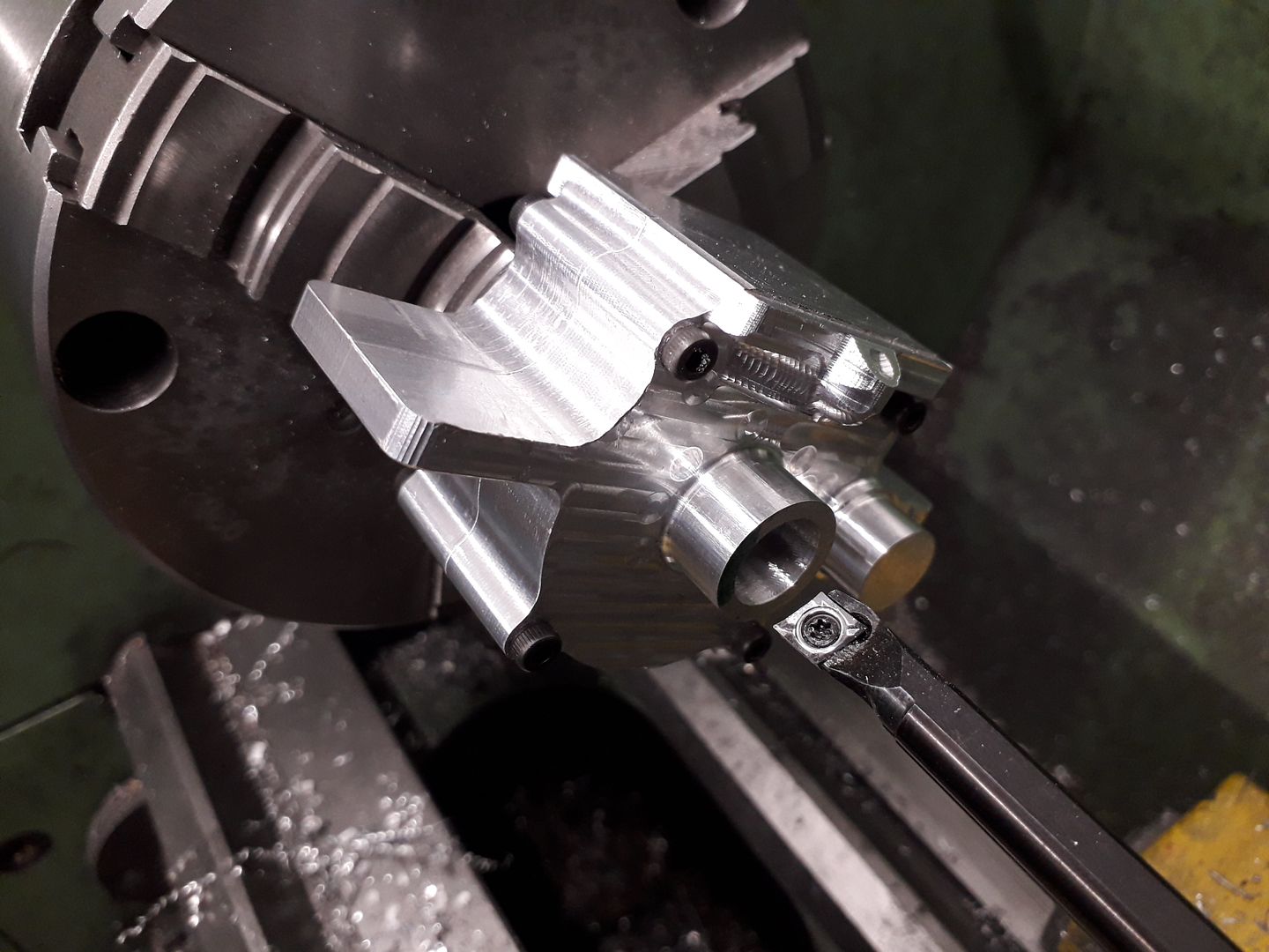
This was then turned in much the same way except a spigot was left rather than the recess.
I also started cleaning up the machining marks with needle & reiffer files and Emery cloth.
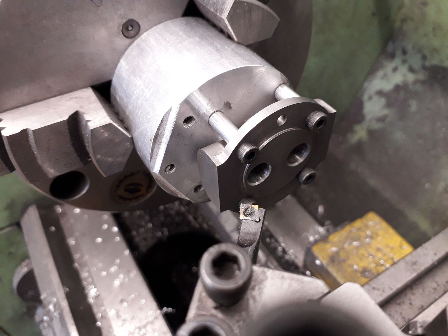
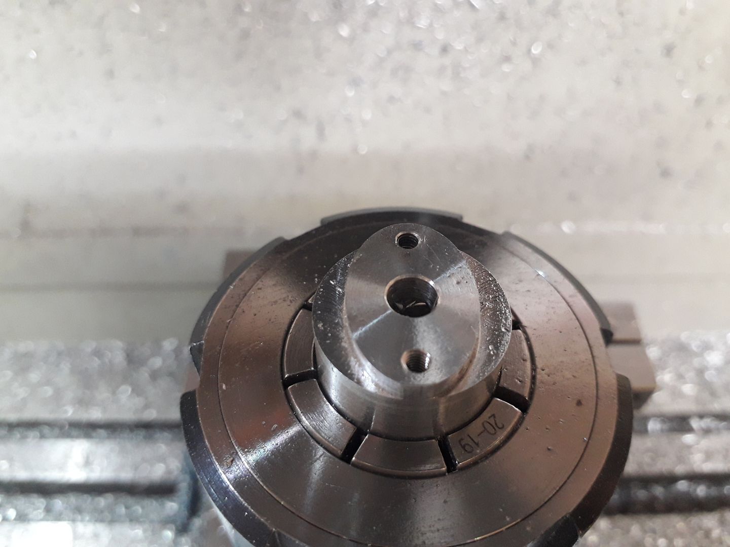
The screw holes were reamed to 4mm and some dowels made with M3 tapped holes each end. These also help keep the two halves lined up and are again another feature of my own. It was now possible to hold both halves in the lathe to bore both bearing housings at one setting to ensure perfect alignment.
|
| john brown 17 | 14/10/2019 19:07:49 |
| 135 forum posts 3 photos | That is very good work jason ,well done will follow along. john |
| JasonB | 15/10/2019 17:41:17 |
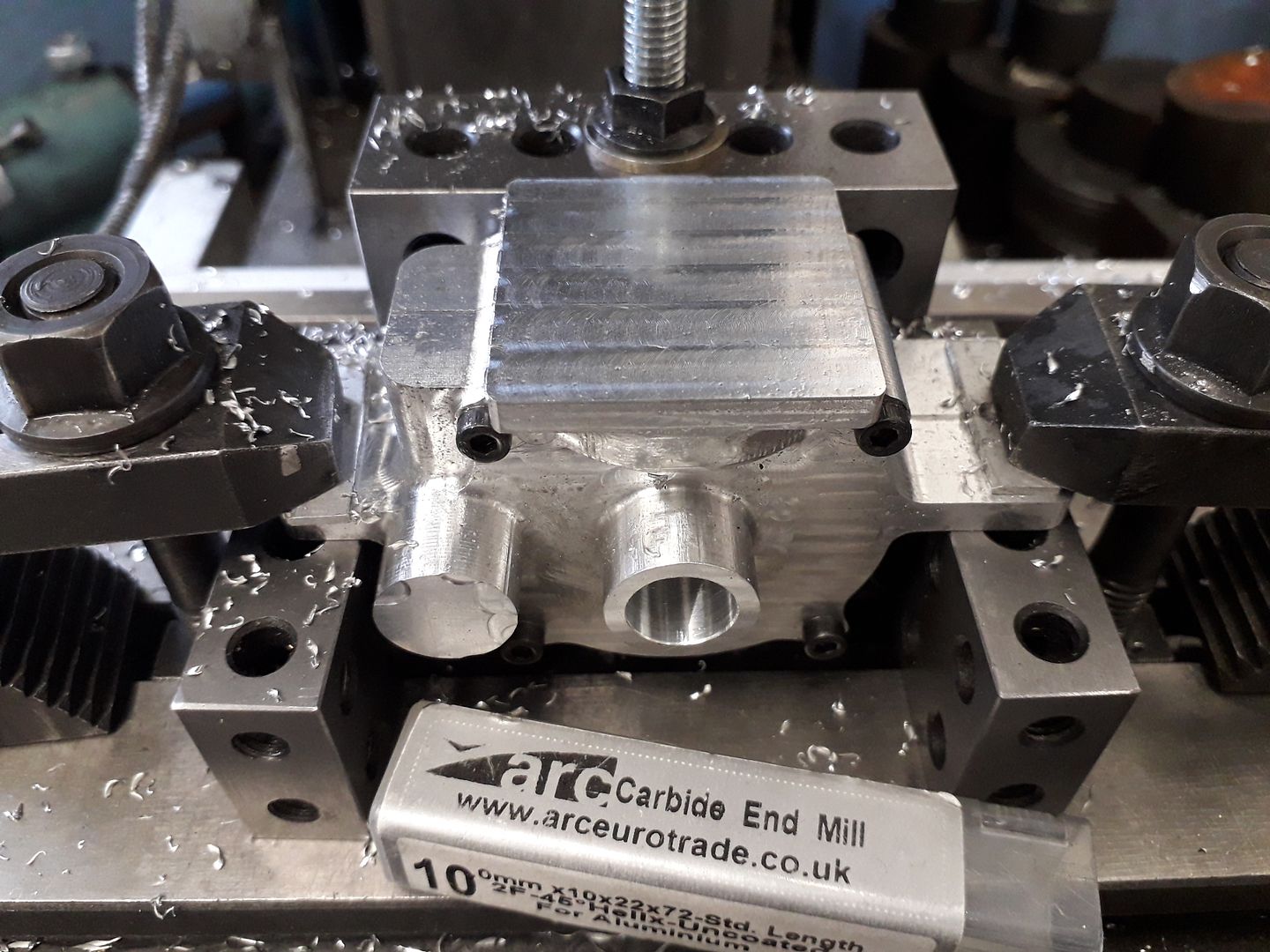
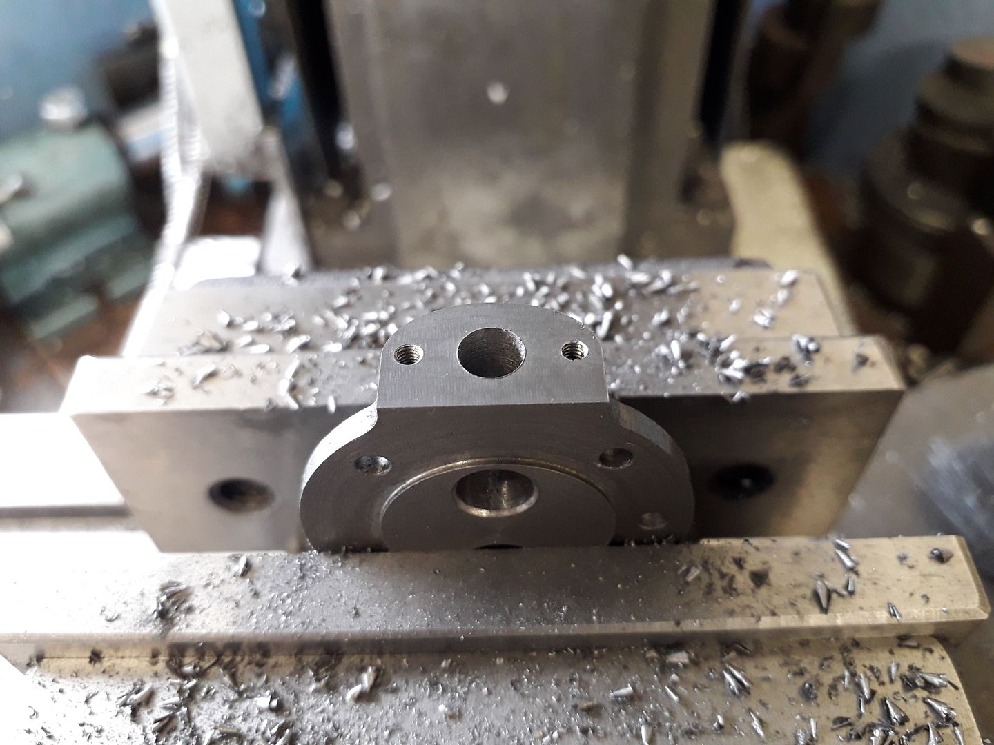
25215 forum posts 3105 photos 1 articles | Thank's John. The next job on the crankcases was to mill off the last 0.5mm that I had left on the cylinder flange. To get things lined up I bolted a 20-40-80 block along the X-axis and clocked that true and with the ends of the main bearing and cam bearing housings against that the case was true in X&Y. A couple of 15-30-60 blocks supported the two mounting lugs.
The top was then opened up by drilling and then taken to final diameter and depth with the boring head. The four cylinder screw holes were also drilled and tapped M3 at the same setting.
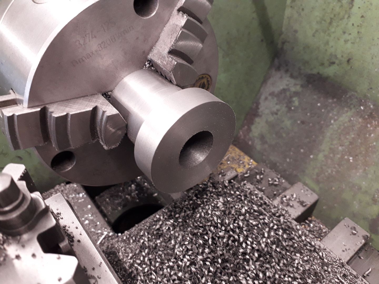
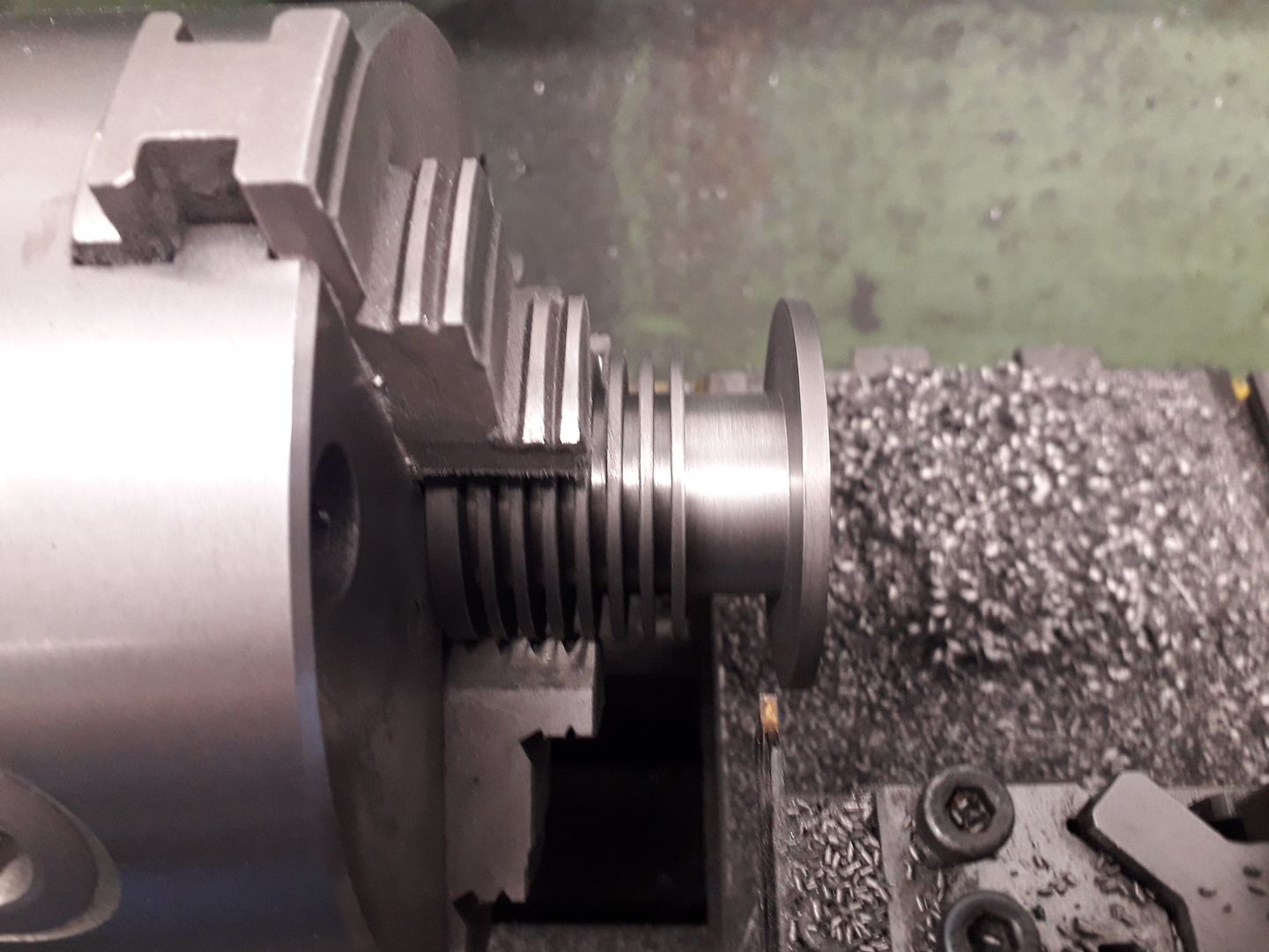
Leaving the crankcases for the moment A piece of cast iron for the cylinder was turned down to the diameter of the fins and then held by this reduced diameter to face the end and bore out to 24mm
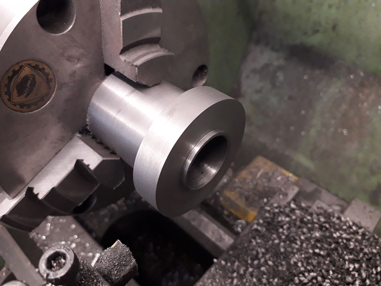
Before cutting a spigot on the end to locate in the crankcase.
Like a lot of parts I make one was used to gauge the size of the other, I think this fit is about right.
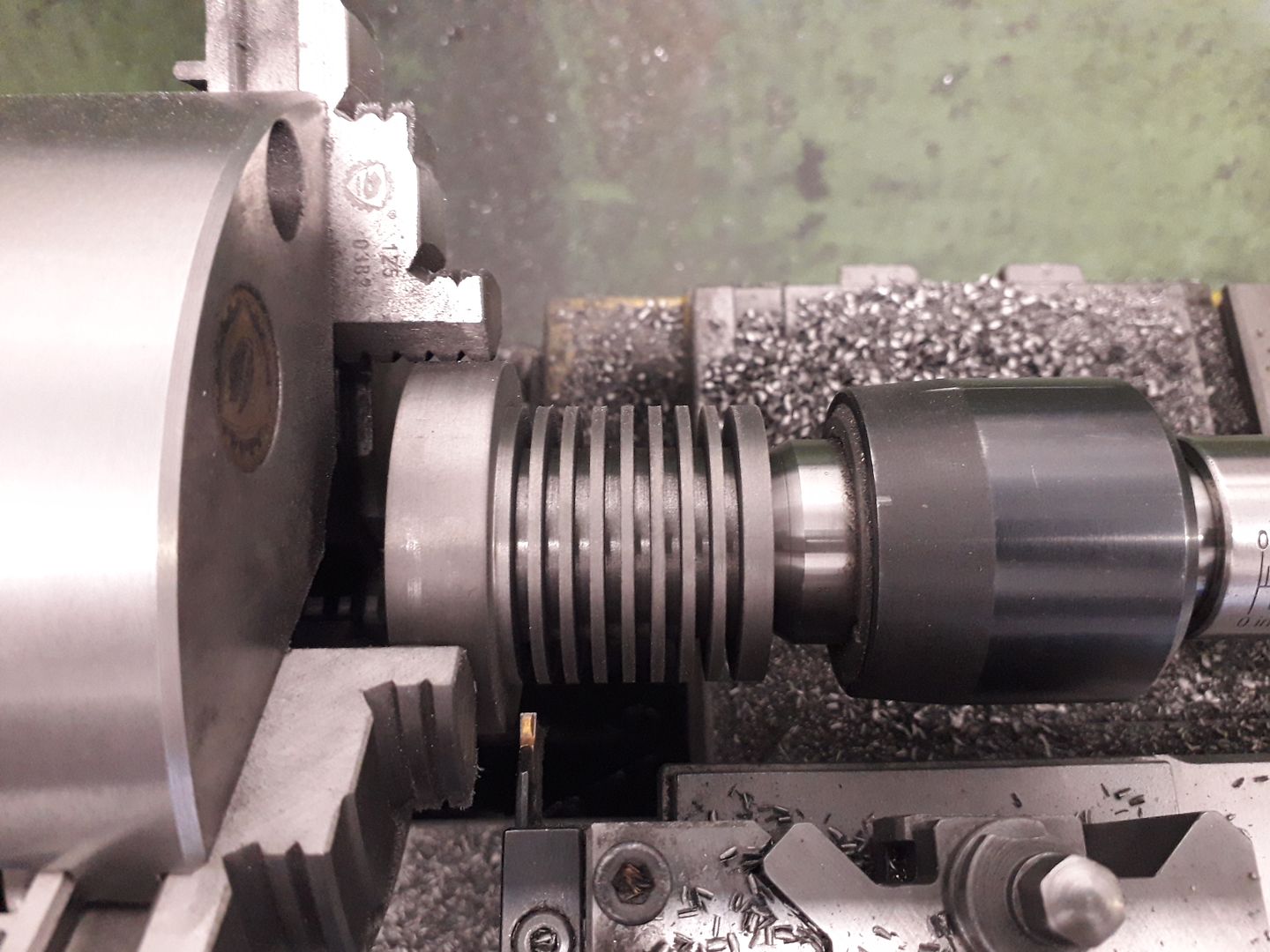
The cylinder was again reversed in the chuck and with tailstock support the slots between the fins were added with an insert parting tool
The last turning job now that I did not need anything too solid to hold by was to machine the waist between fins and mounting flange
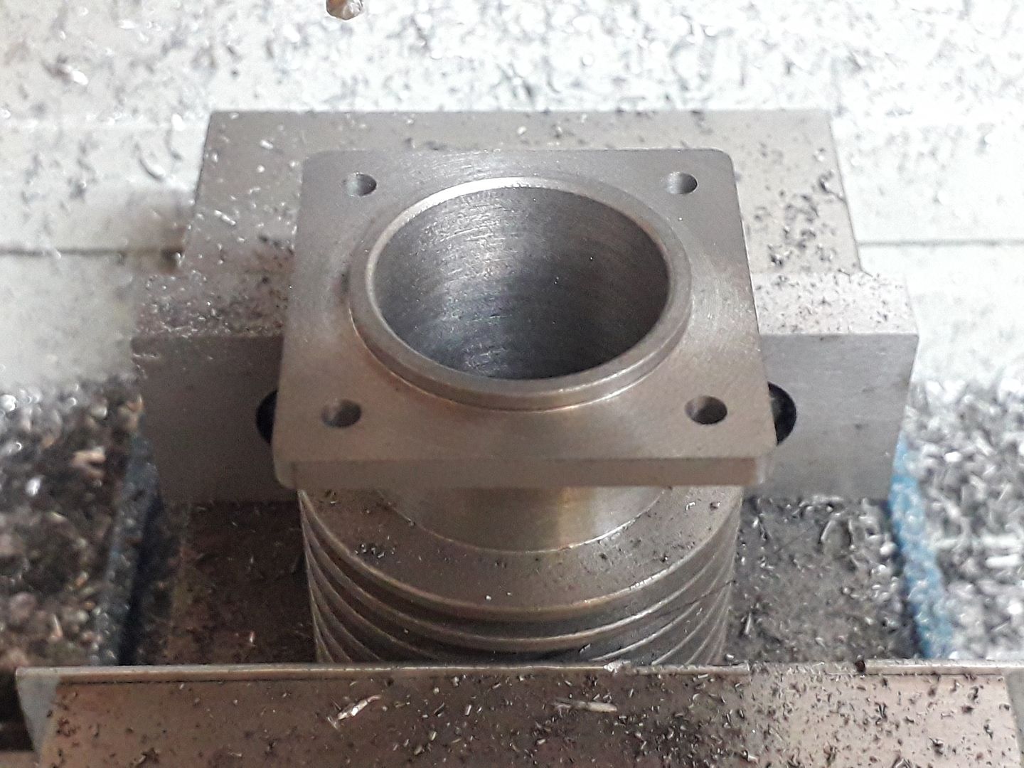
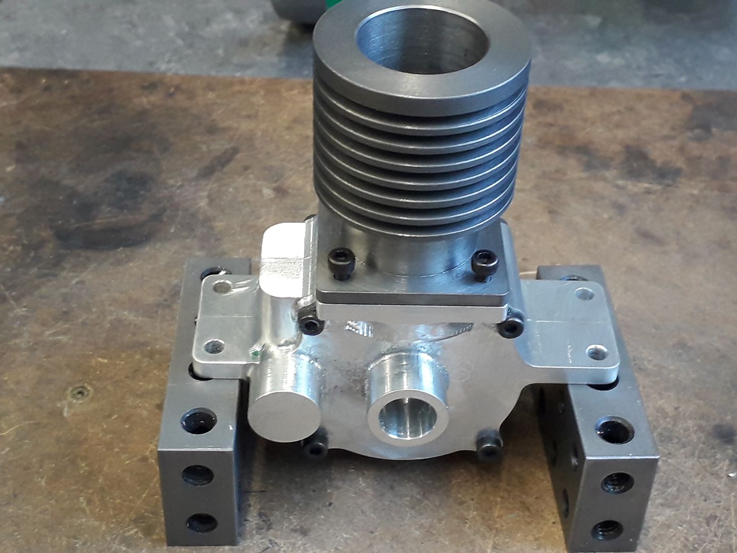
As I wanted the practice on the CNC I used that to give the flange it's square shape with rounded corners and also drill the mounting holes.
That gave me an excuse for a test fit.
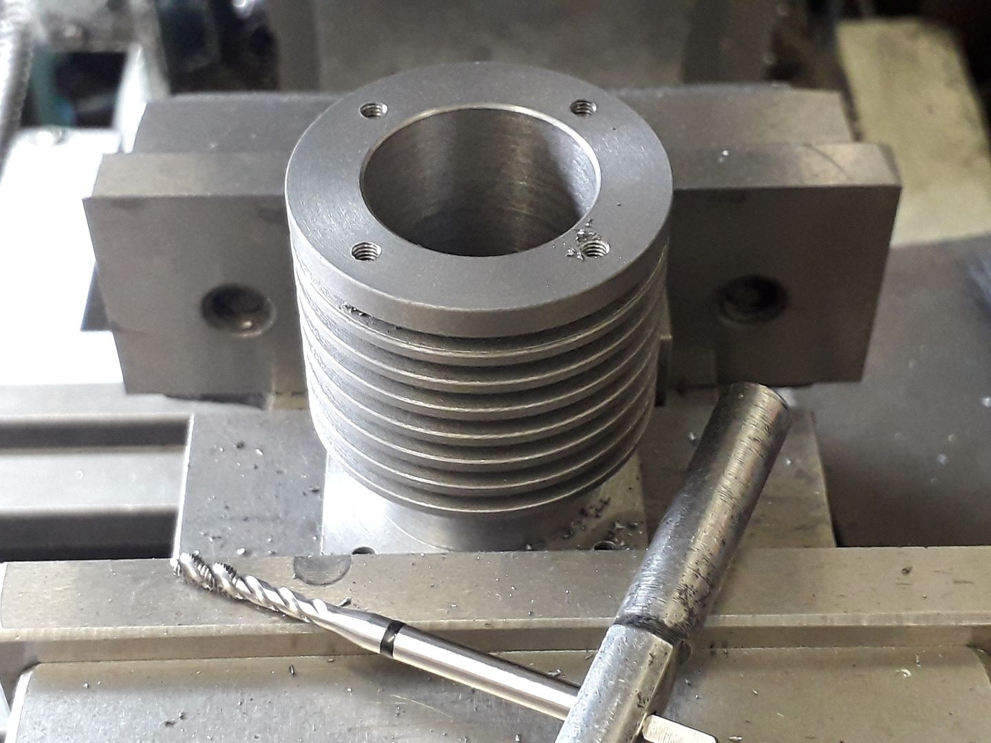
The last machining job on the cylinder was drilling and tapping for the head fixings, the spiral flute taps work just as well on crumbly materials as those that produce long swarf. Just needs a bit of honing to complete.
|
| Ron Laden | 16/10/2019 17:30:37 |
 2320 forum posts 452 photos | Excellent Jason, I do enjoy your build threads mainly because I usually learn something from them as well as admiring your work of course. Great stuff. |
| JasonB | 16/10/2019 19:18:19 |
25215 forum posts 3105 photos 1 articles | Thanks for the interest Ron.
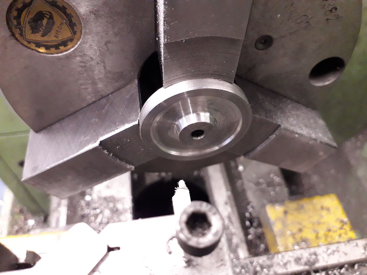
Luckily I was able to keep the same 21/42 tooth count on the timing gears by using MOD0.8 which gave a suitable PCD distance. So first job was to machine the blanks, this is the larger gear that has had the faces recessed.
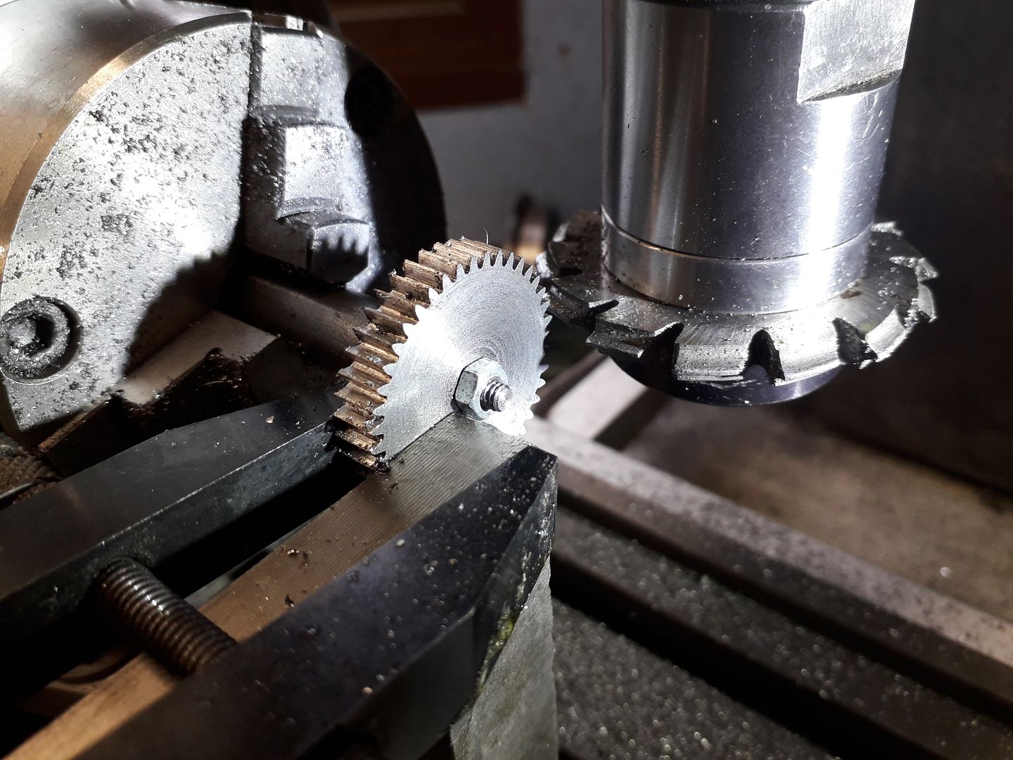
Unfortunately when cutting the teeth on this one the 4mm central hole was not upto holding it still and the gear crept on thearbor, it was also quite chattery. So another blank was cut but this time left flat faced and an angle plate placed against the blank so it could also be clamped to that with a toolmakers clamp and all went well. I also used 32DP cutters but cut to the MOD0.8 dimensions as there is so little difference between the two and I had the 32DP cutters.
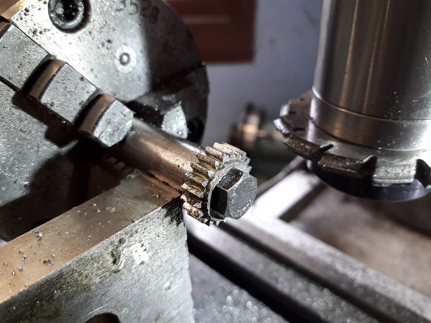
The smaller 21T gear was not a problem having a 10mm hole though I did butt the angle plate up against the arbor to stop any deflection.
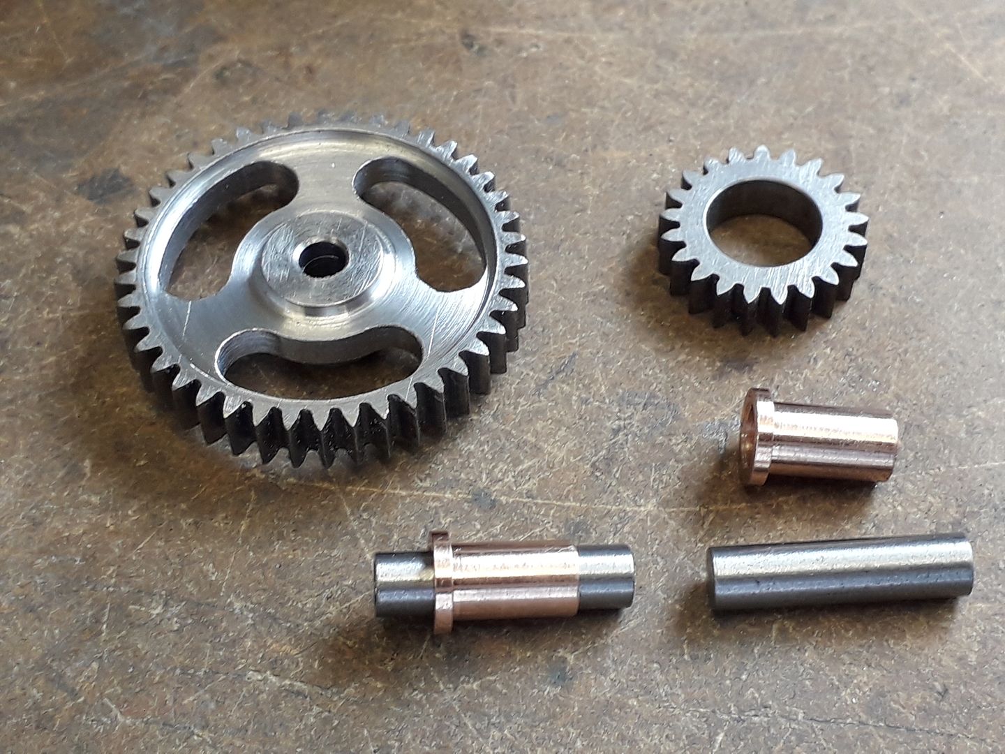
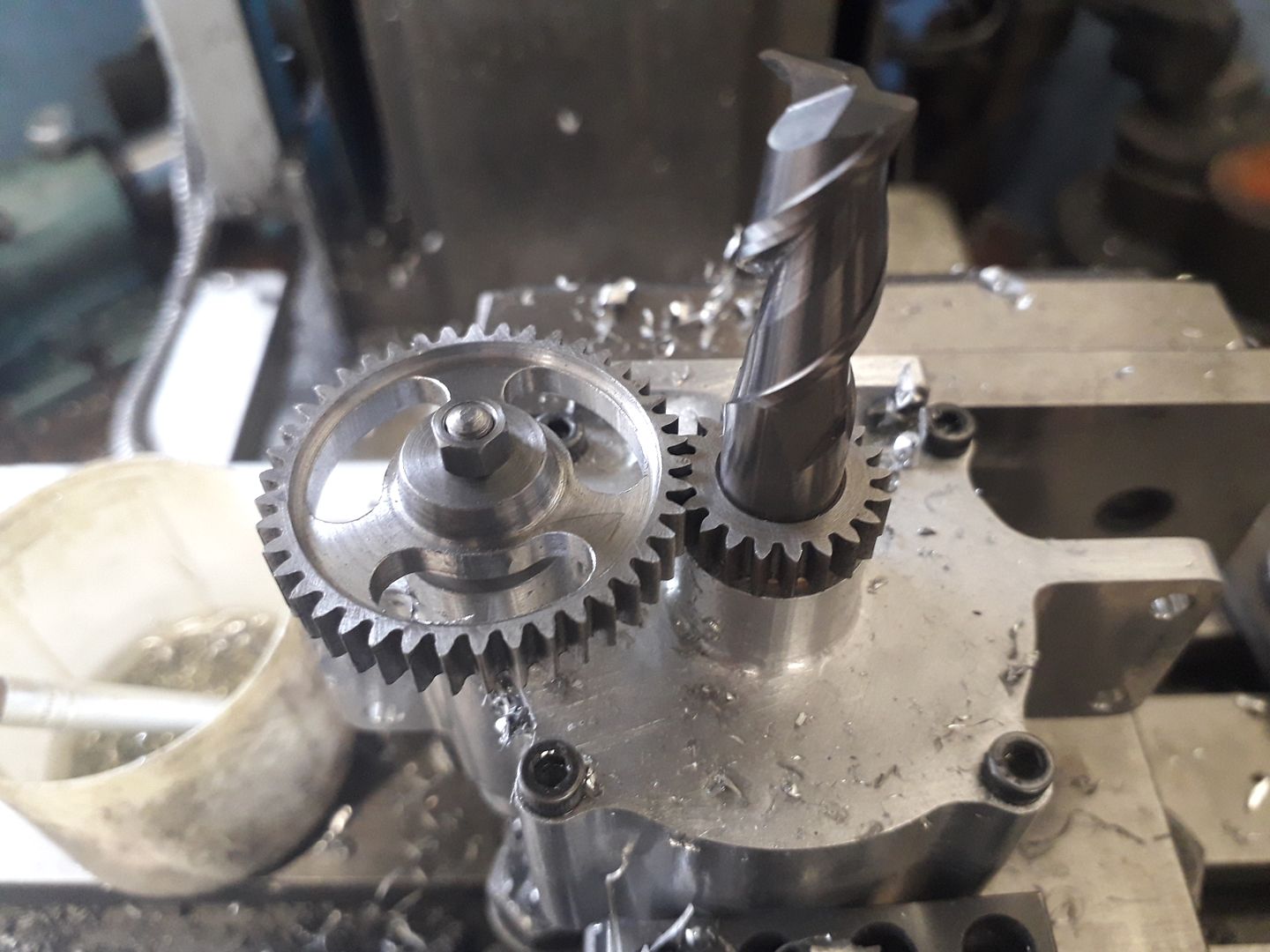
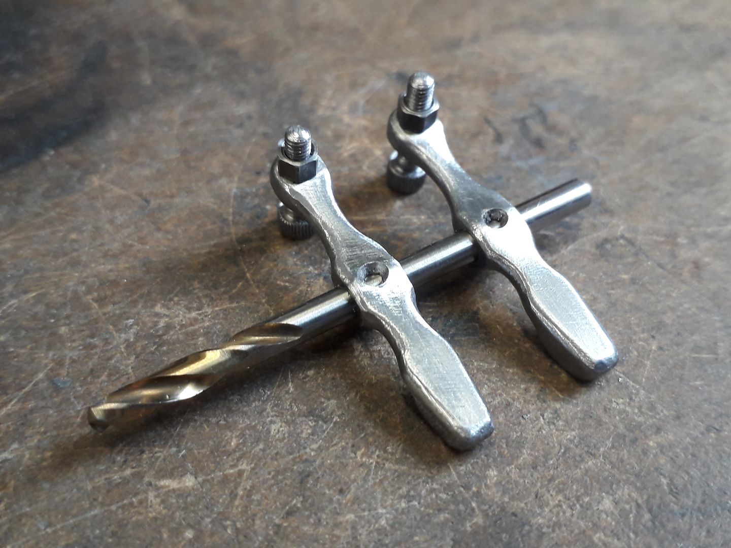
The large gear was then recessed and some weight reducing slots added more for looks than performance. Also in the photo are the two silver steel (drill rod) tappets and some bronze guides that I decided to include rather than having them run in the plain crankcase holes as shown on the original design.
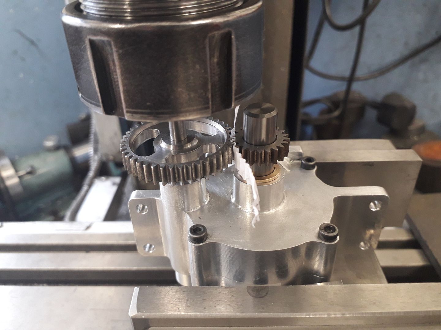
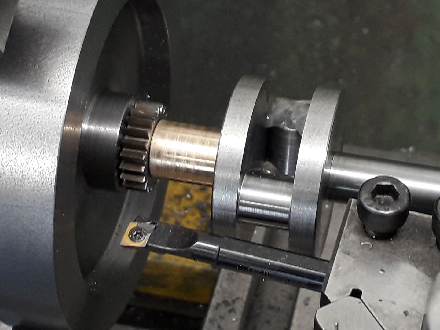
The crankcases were then held in the mill vice and with a 10mm dia carbide cutter shank in the main bearings to support the small gear and the large gear mounted on the camshaft blank held in a collet the backlash was set and the DRO zeroed so that the holes for the camshaft bearings could be reamed in the exact position required.
All seemed to run smoothly enough .
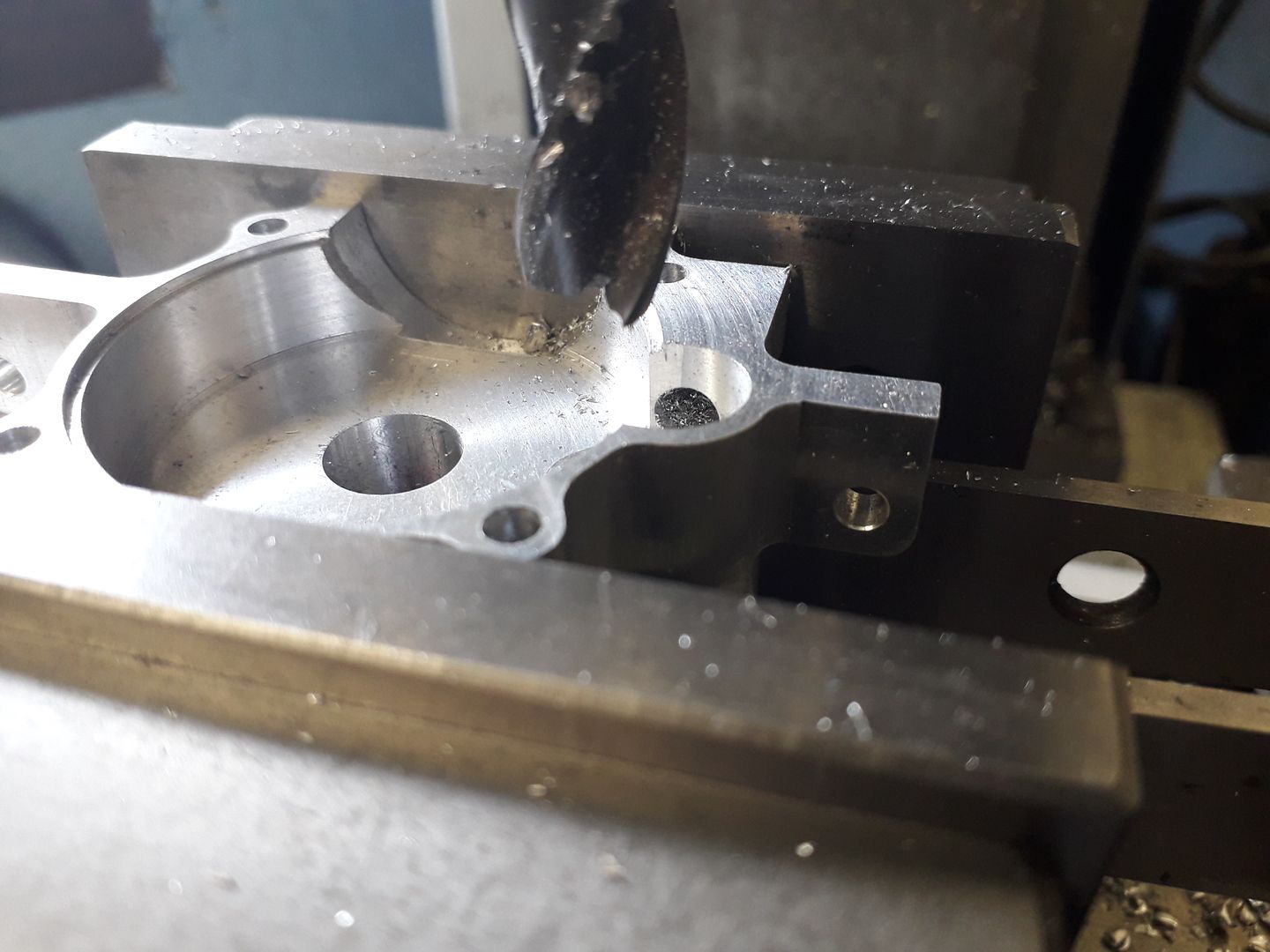
With the holes done I split the crankcase halves so that the hole could be located on the mill and a recess opened up to give clearance for the cams.
|
| Ron Laden | 17/10/2019 16:28:43 |
2320 forum posts 452 photos | Jason, out of interest what material are the timing gears cut from, also do you cut each position to full depth before moving to the next or do you work around the gear gradually increasing the depth. |
| JasonB | 17/10/2019 16:58:51 |
25215 forum posts 3105 photos 1 articles | Just a bit of EN1A for those as they don't really take any load and I'm not going to be running it for hours on end. Each tooth cut in one pass then move on to the next, Andrew would slap my wrists if I did any different |
| JasonB | 18/10/2019 20:06:02 |
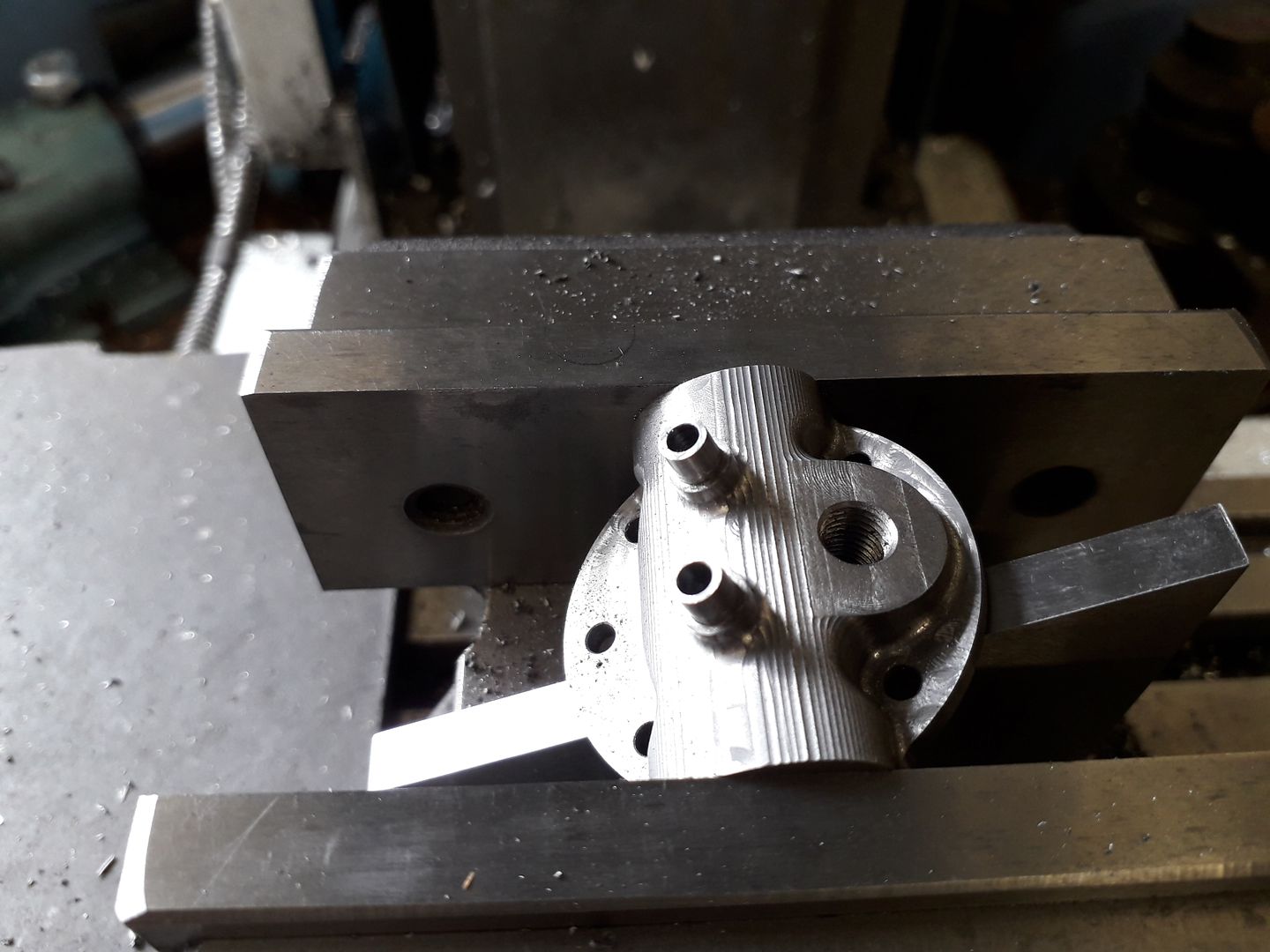
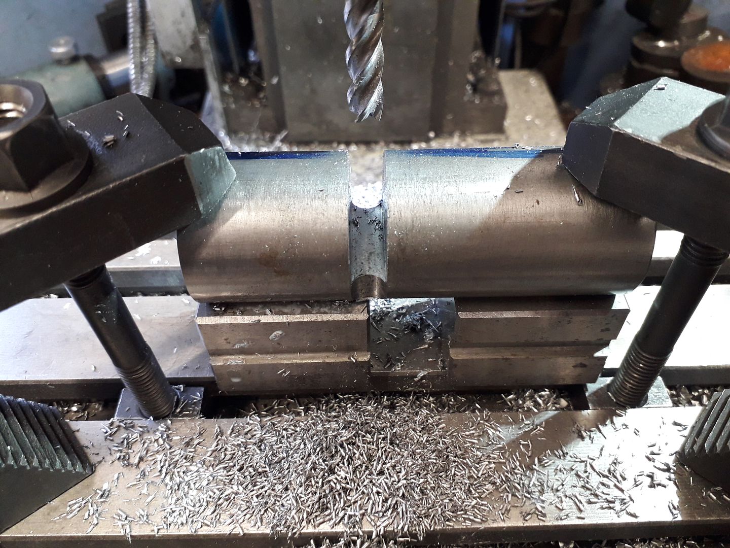
25215 forum posts 3105 photos 1 articles | I made a couple of changes to the cylinder head, the most obvious is a separate post for the rockers to pivot on rather than one cast integral to the head. The other difference was to omit the way that the valve guide extends into the valve chambers and to retain the length of guide these were extended further above the head which also meant I could machine a step to help locate the valve spring. I started by facing some cast iron bar in the lathe and forming a shallow spigot to locate in the bore. Then over to the mill and two holes were drilled and tapped into the valve cavities which allowed me to screw the head to a block that could easily be held in the CNC mill's vice. I could have set a finer step down on the contouring cuts which would have needed a bit less finishing but was happy to need a bit more filing as that would give a bit more variance that gives a more "cast" look.
I always prefer to bore my valve cavities, ream the guides and machine the seats with a boring bar all at one setting and find this needs very little lapping and results in a good sealing valve. To do this a simple jig was made up consisting of a bit of bar with 4 offset tapped holes and 4 standoffs, it was then just a case of screwing the head to this to do one valve and then taking it off, rotating 180deg and screwing back on to do the other.
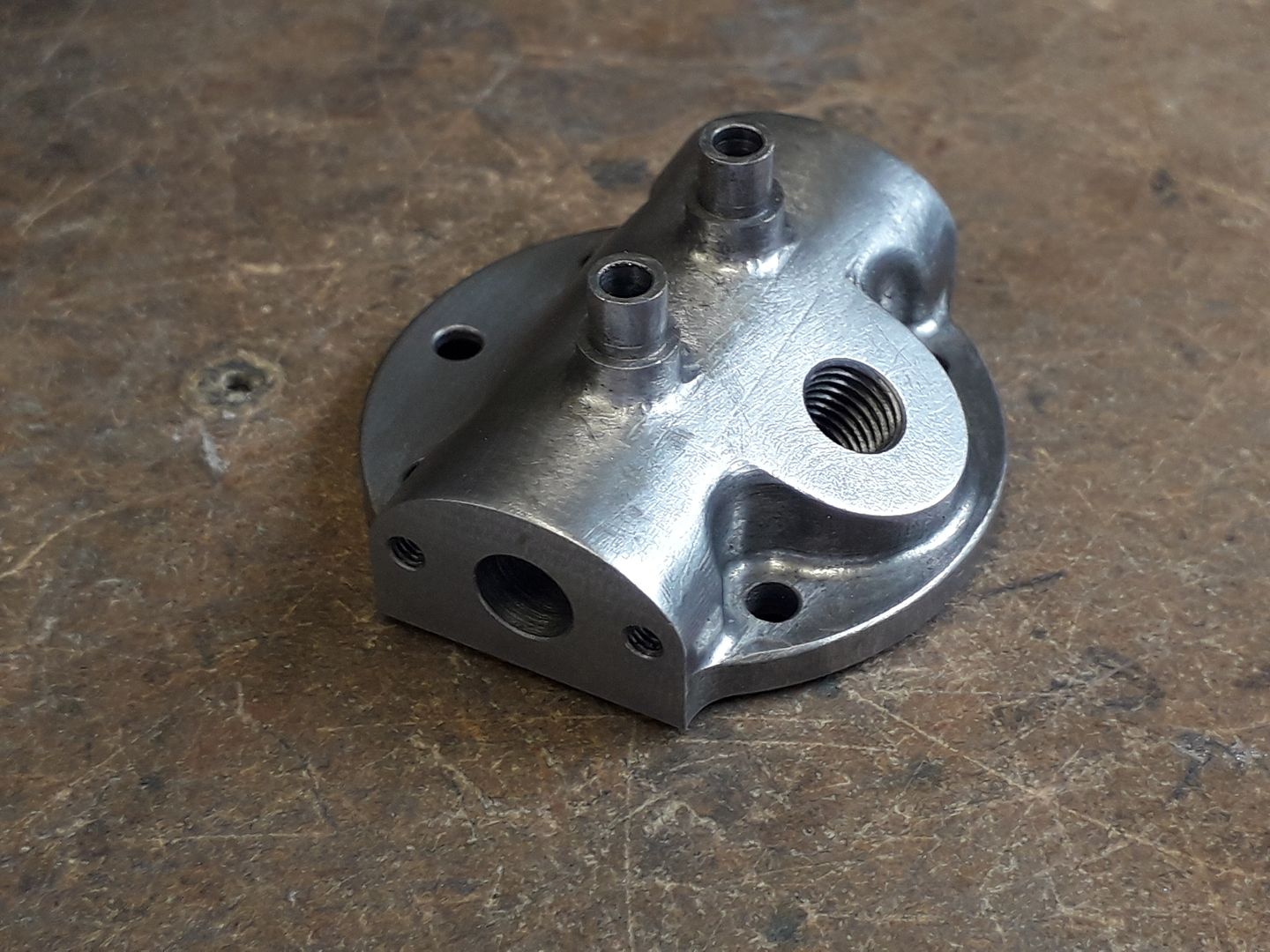
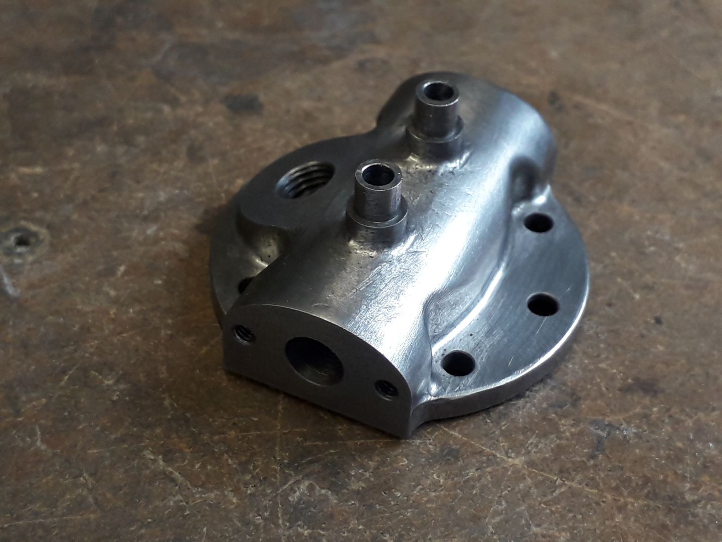
It was then over to the manual mill to drill the exhaust and inlet passages as well as adding the M2.5 tapped holes for the carb and exhaust flanges.
An angle gauge was used to set the head in the vice so that the spark plug face could be skimmed and the 1/4" x 32 threaded hole for the Rimfire plug added.
The last thing to do was remove the contour lines left by the CNC with the aid of needle files and that was the head complete.
Edited By JasonB on 18/10/2019 20:06:33 |
| Ron Laden | 19/10/2019 09:42:23 |
2320 forum posts 452 photos | The head turned out well Jason and it really does look as if its come from a casting. |
| Ron Laden | 19/10/2019 19:43:11 |
2320 forum posts 452 photos | Jason, I am intrigued by the throttle adjustment which I think you said was operated by revolving the fuel jar, can you explain how that works. |
| JasonB | 19/10/2019 20:13:58 |
25215 forum posts 3105 photos 1 articles | Ron, it's a fairly basic barrel carb and by having the jar lid as part of the barrel/spray bar assembly the lid and therefor the jar act just like a lever would on a RC model carb, I could also add a thin lever between lid and barrel if I wanted. Couple of pics with the actual body removed so you can see the assembled parts that all rotate as one.
|
| Ron Laden | 20/10/2019 07:53:10 |
2320 forum posts 452 photos | Thanks Jason for the explanation and drawings. |
| JasonB | 20/10/2019 17:44:49 |
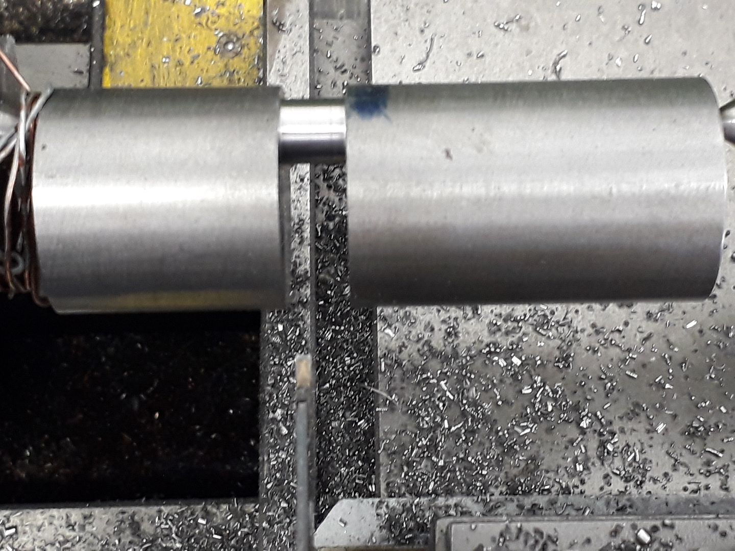
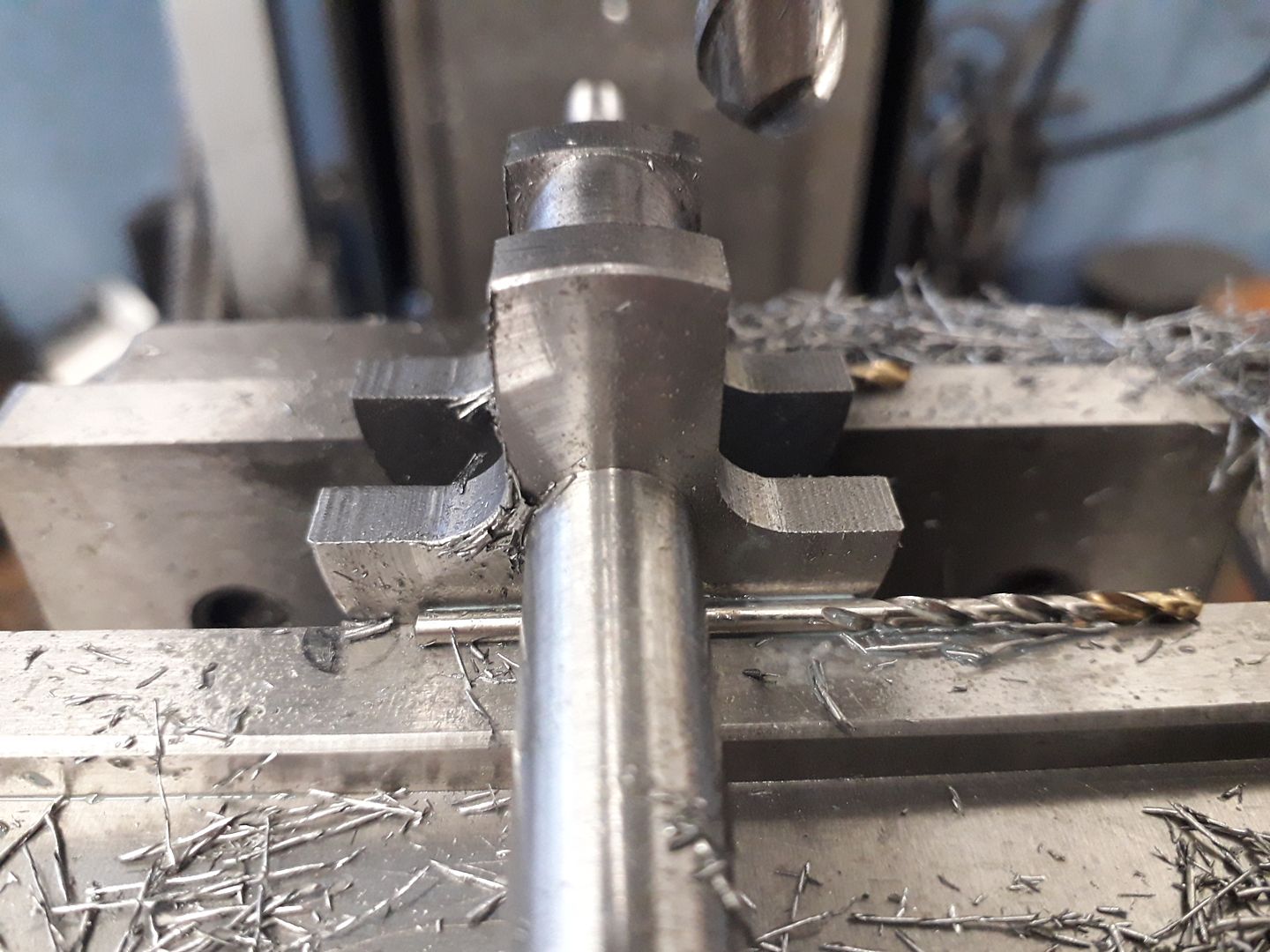
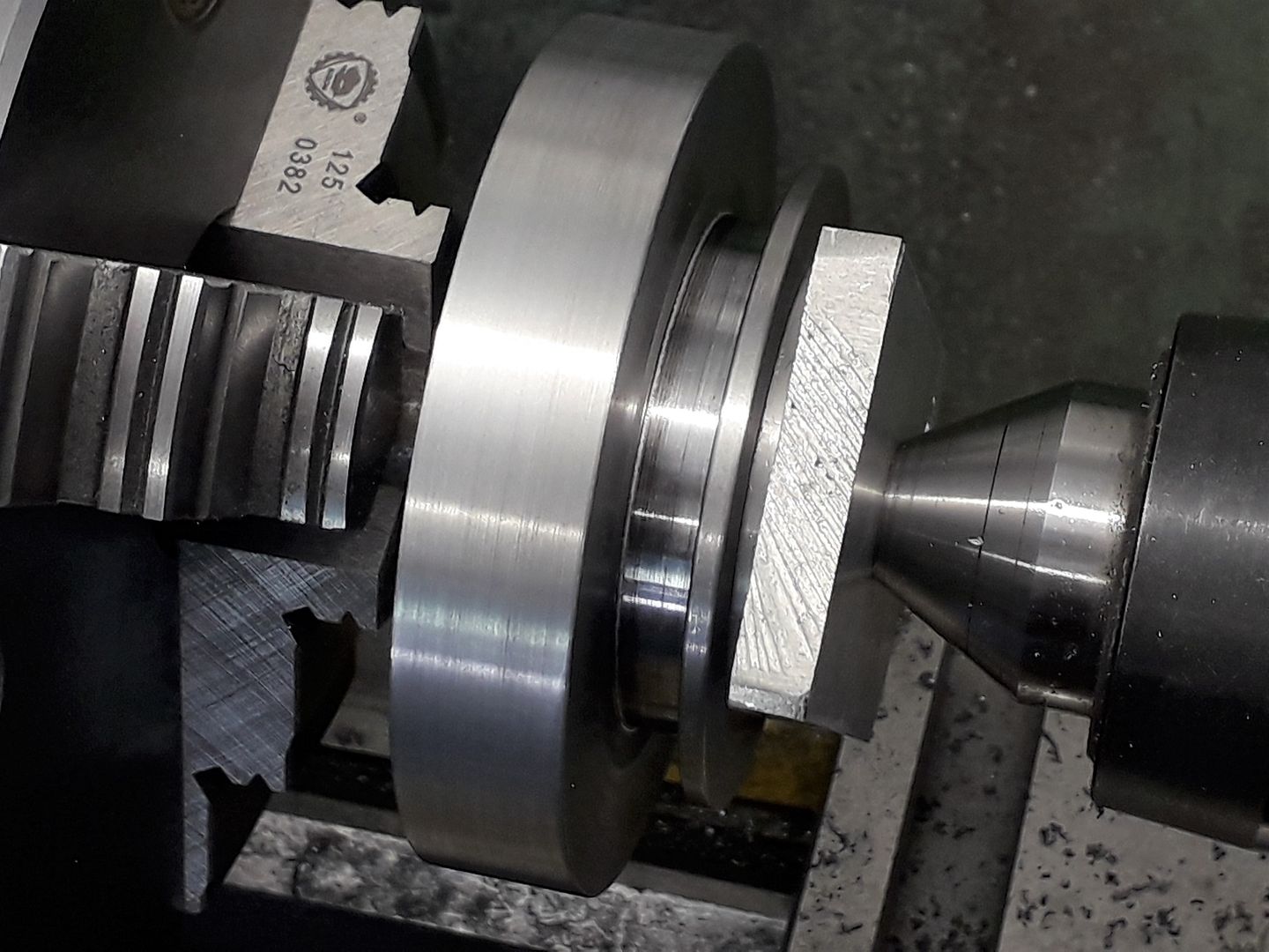
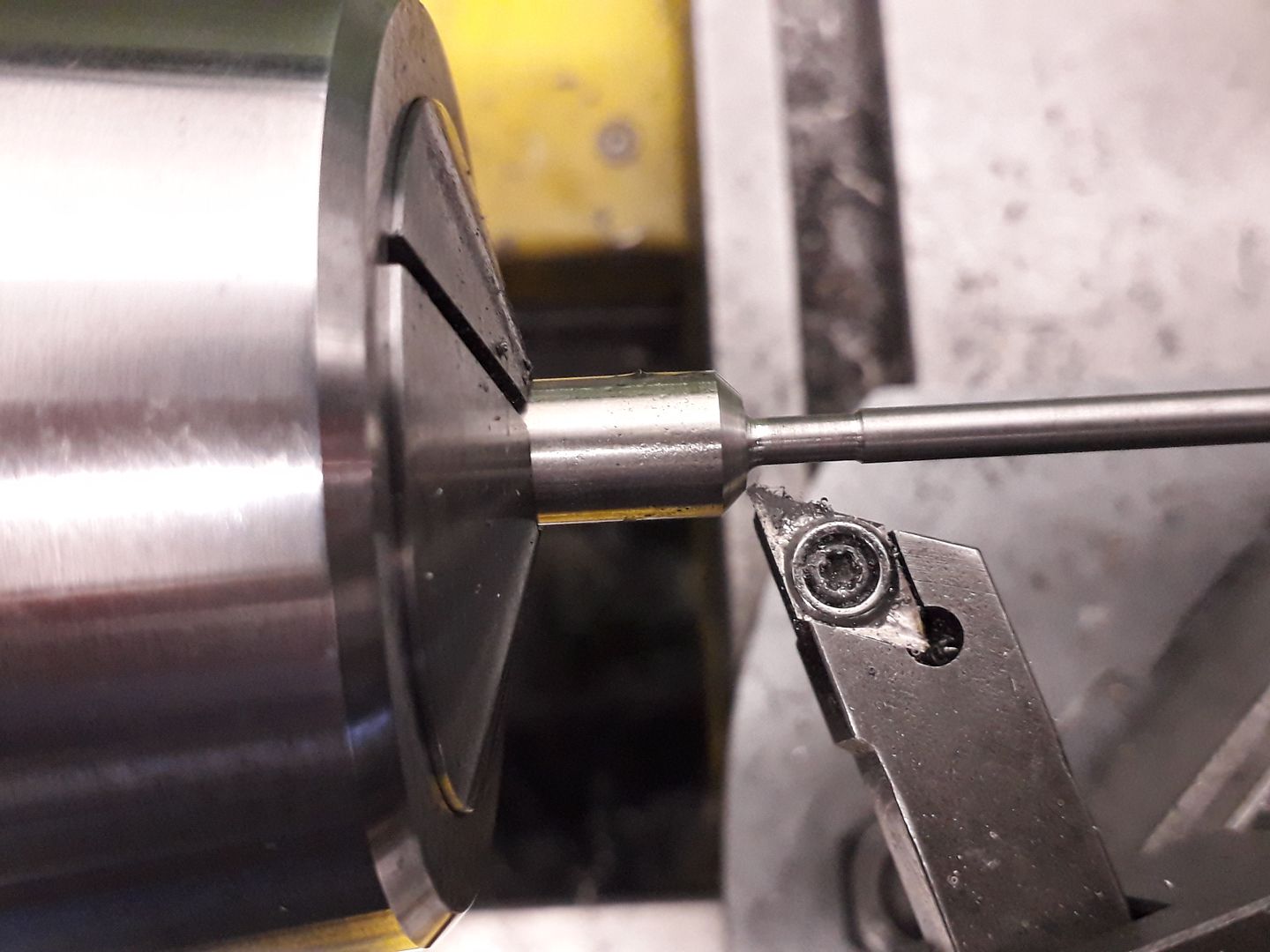
25215 forum posts 3105 photos 1 articles | The crankshaft started out as a length of EN8 steel that was faced to length and ctr drilled for the throw and shaft centers before milling out most of the waste around the pin which is a lot faster and easier than turning it away. I left it for a week to settle after this but it did nor show any signs of having moved.
Then the pin and inner webs were turned, I used a boring bar for the left hand web and an HSS knife tool for the right, the pin was completed with a modified parting tool that has had the middle of the cutting edge ground away with a Dremel which stops any chatter as the tool is worked from side to side as a fine cut is put on.
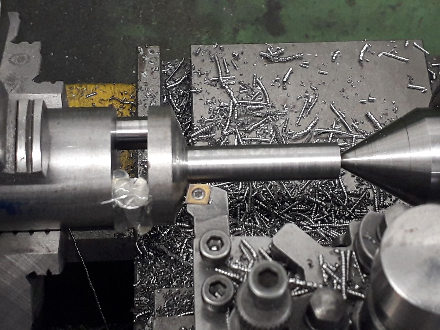
I then rough turned the ends down using a holder that takes the "other two" corners of a CCMT insert while holding the web in the chuck.
Final finishing was done between centers using a DCMT insert which again helps reduce chatter and will also take off a fine cut.
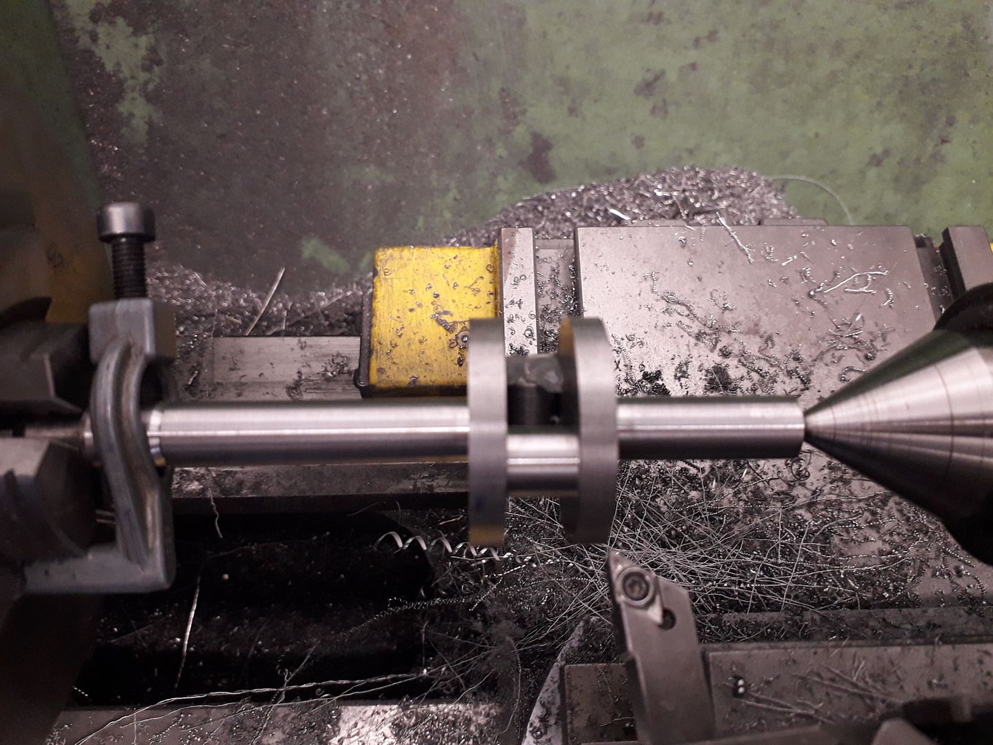
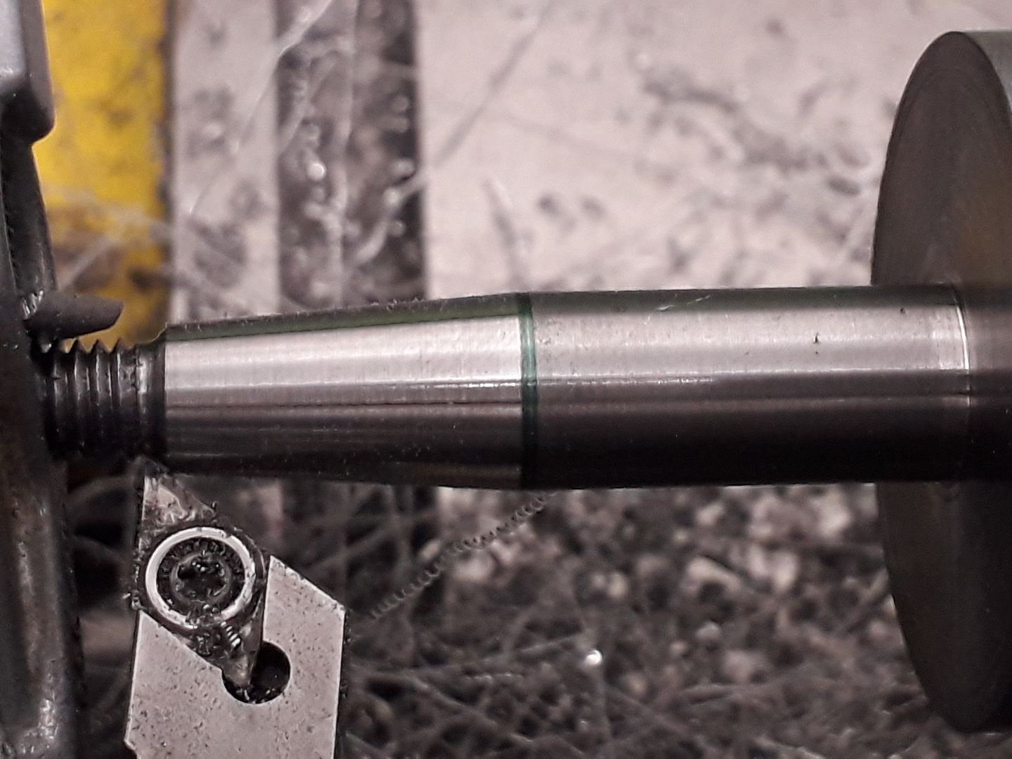
I also turned and rough bored the flywheel at this stage but more of that later. Last jobs for the lathe were to screwcut a thread on the end and then cut the taper for the flywheel, doing it at the chuck end makes it easy to bore the flywheel at the same topslide setting.
Finally back to the mill to shape the webs to give some counterbalance.
|
| Ron Laden | 20/10/2019 20:00:52 |
2320 forum posts 452 photos | I am impressed Jason, I would never have imagined a one piece crank coming out of a piece of bar like that. |
| JasonB | 24/10/2019 17:13:15 |
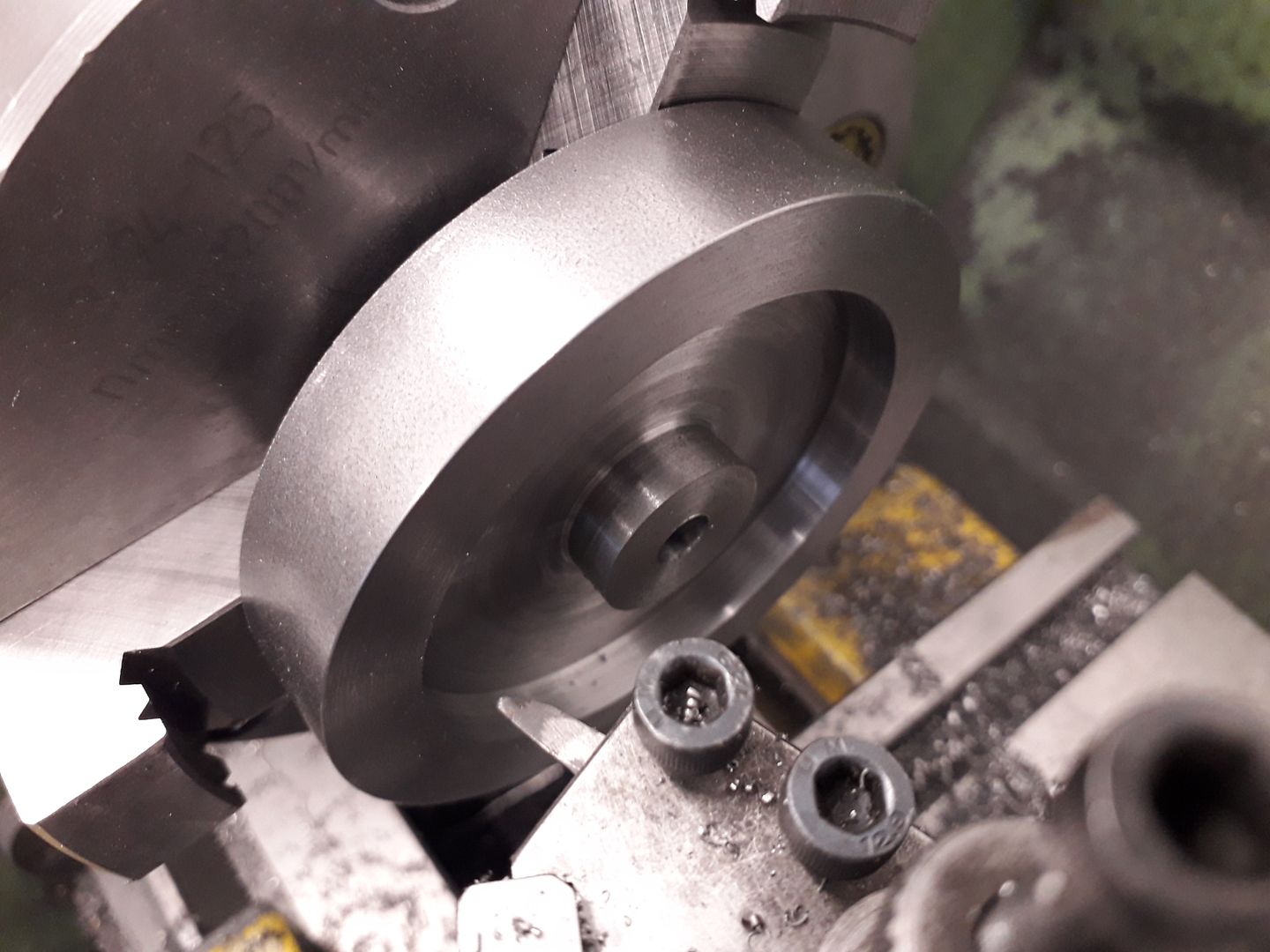
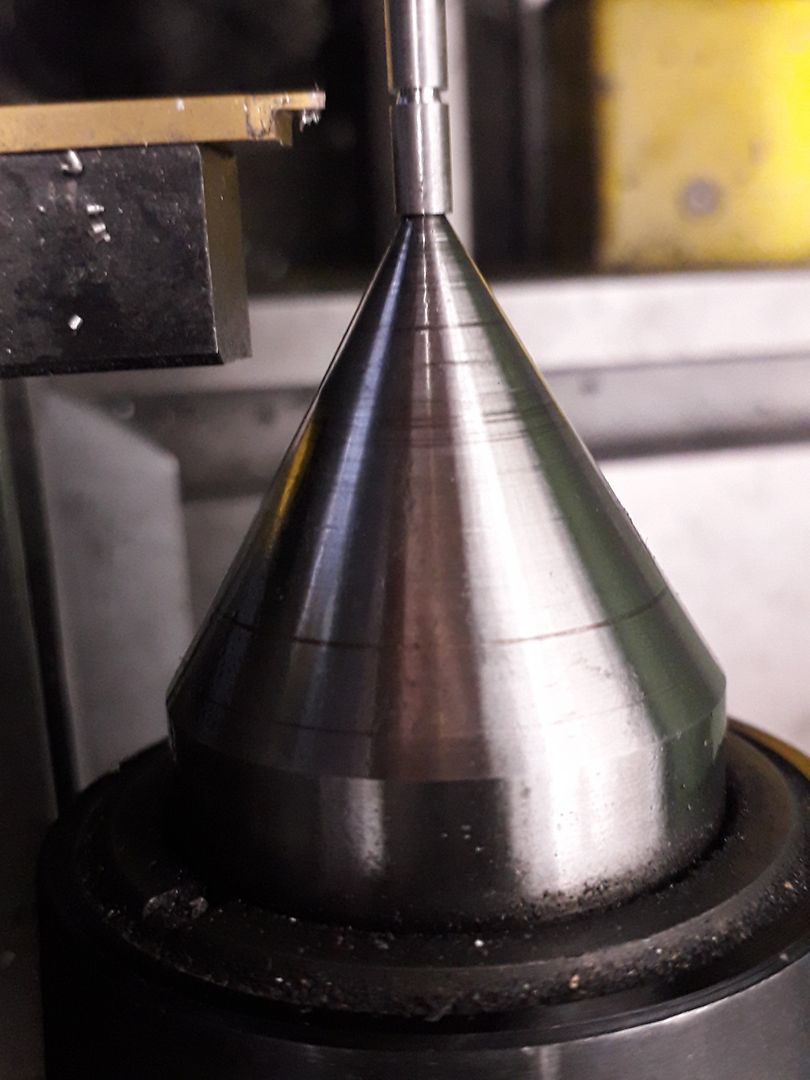
25215 forum posts 3105 photos 1 articles | As I mentioned in the previous post before doing the taper on the crankshaft the flywheel was machined. first job was to recess the sides of a slice of 80mm EN1A steel, by setting over the top slide 2 degrees some draft angle could be included on the outer edge while turning conventionally.
Then buy running in reverse and working on the rear side of the hub that could have the same taper and by noting the topslide handwheel setting it was easy to machine to the correct depth. A tool with a rounded end was used to again give the look of an internal fillet as found on castings.
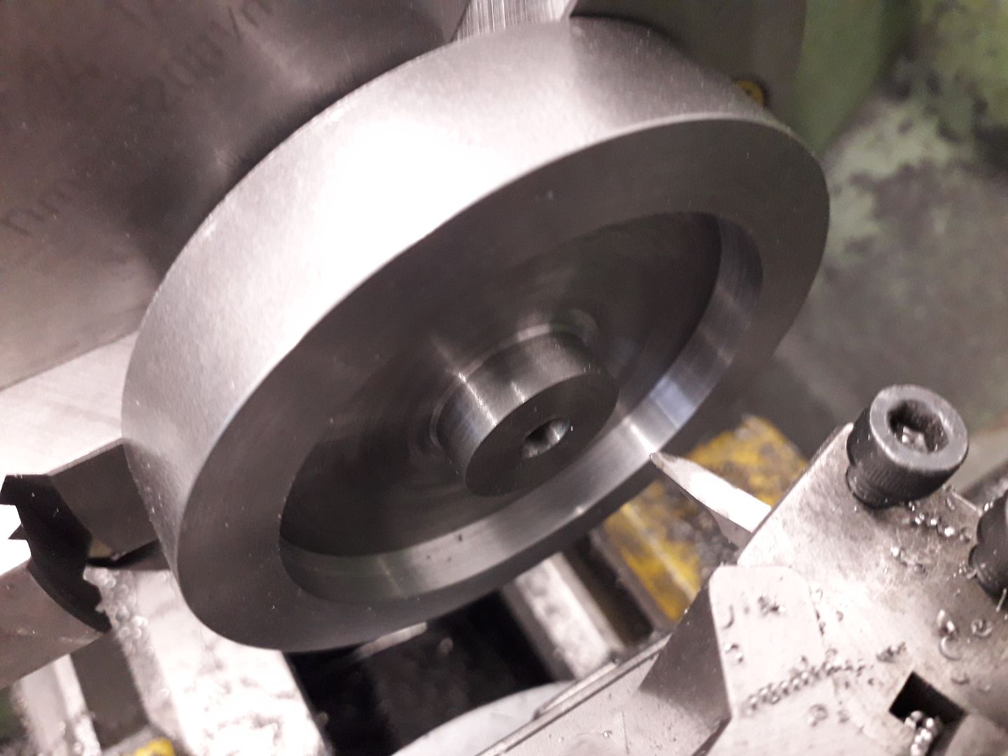
I could now set my topslide to the correct angle for the crankshaft taper and then use that to gauge the depth of the flywheel's tapered bore all without altering the angle so both tapers match. Fine cuts were taken until the shaft entered the flywheel and left 0.5mm clearance between the assembled bearing and timing gear.
Without altering the topslide angle I also machined a tapered arbor and pushed the flywheel onto that using a block and the tailstock ctr to make sure it stayed in place which allowed me to skim the OD to a true finish relative to the bore and cut the recess for the starting cord.
The arbor did not go to waste, with it held at an angle in an ER Collet block a slot was cut so that it could be used as a bush when broaching the flywheel.
|
| JasonB | 25/10/2019 19:19:19 |
25215 forum posts 3105 photos 1 articles | The two rocker arms were mostly done using the CNC, first roughing out the profile and contour and then using a corner radius cutter to refine the shape before drilling the pivot hole. After that they were sawn off the parent bar and held in some shaped aluminium jaws to shape the other side. The adjuster and oil holes were done on the manual mill, pivot hole reamed and some final needle file work soon had the contours blended in.
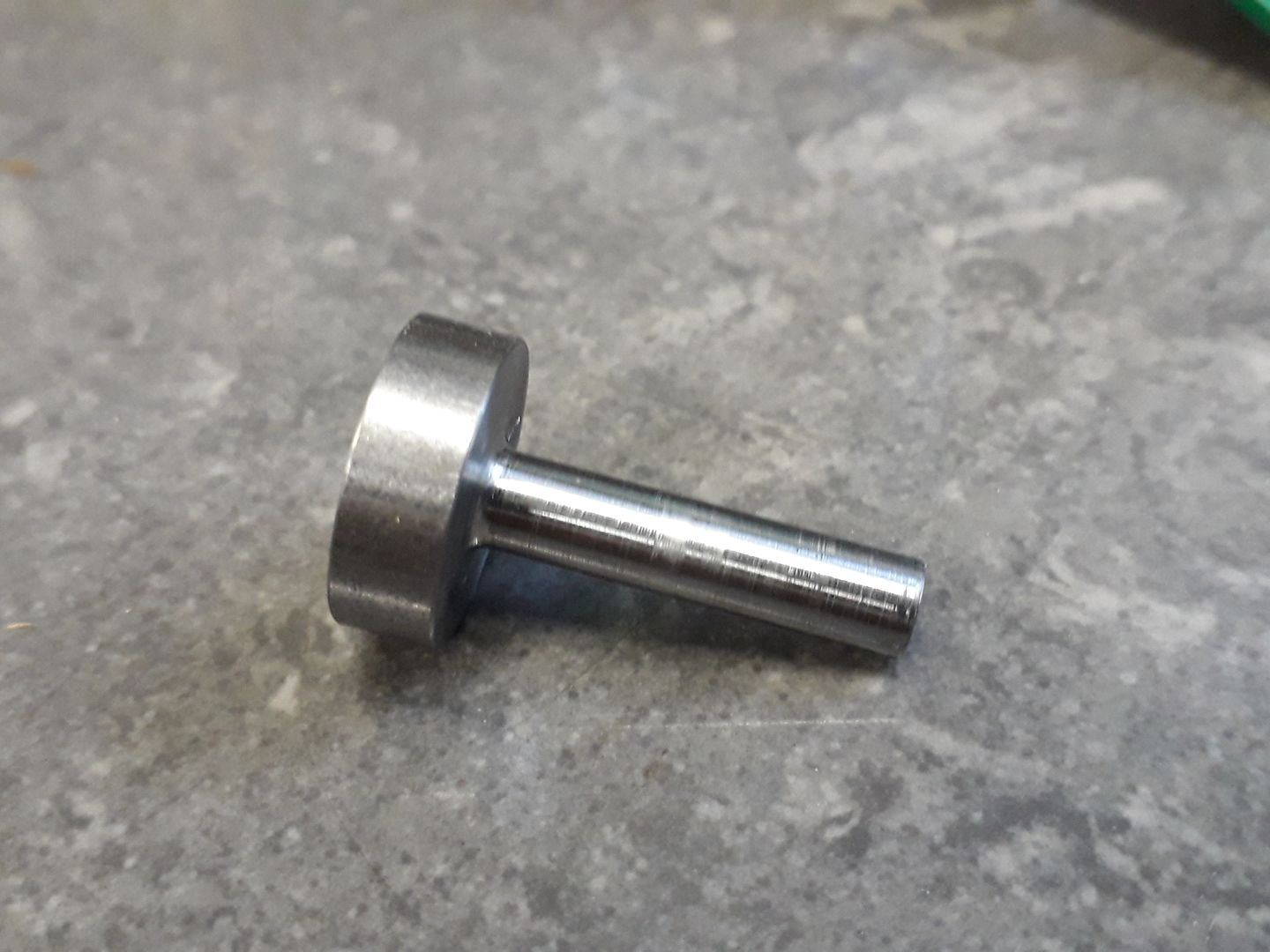
The rocker post started as a simple turned part.
Which was the milled and reamed before a bit more shaping was carried out.
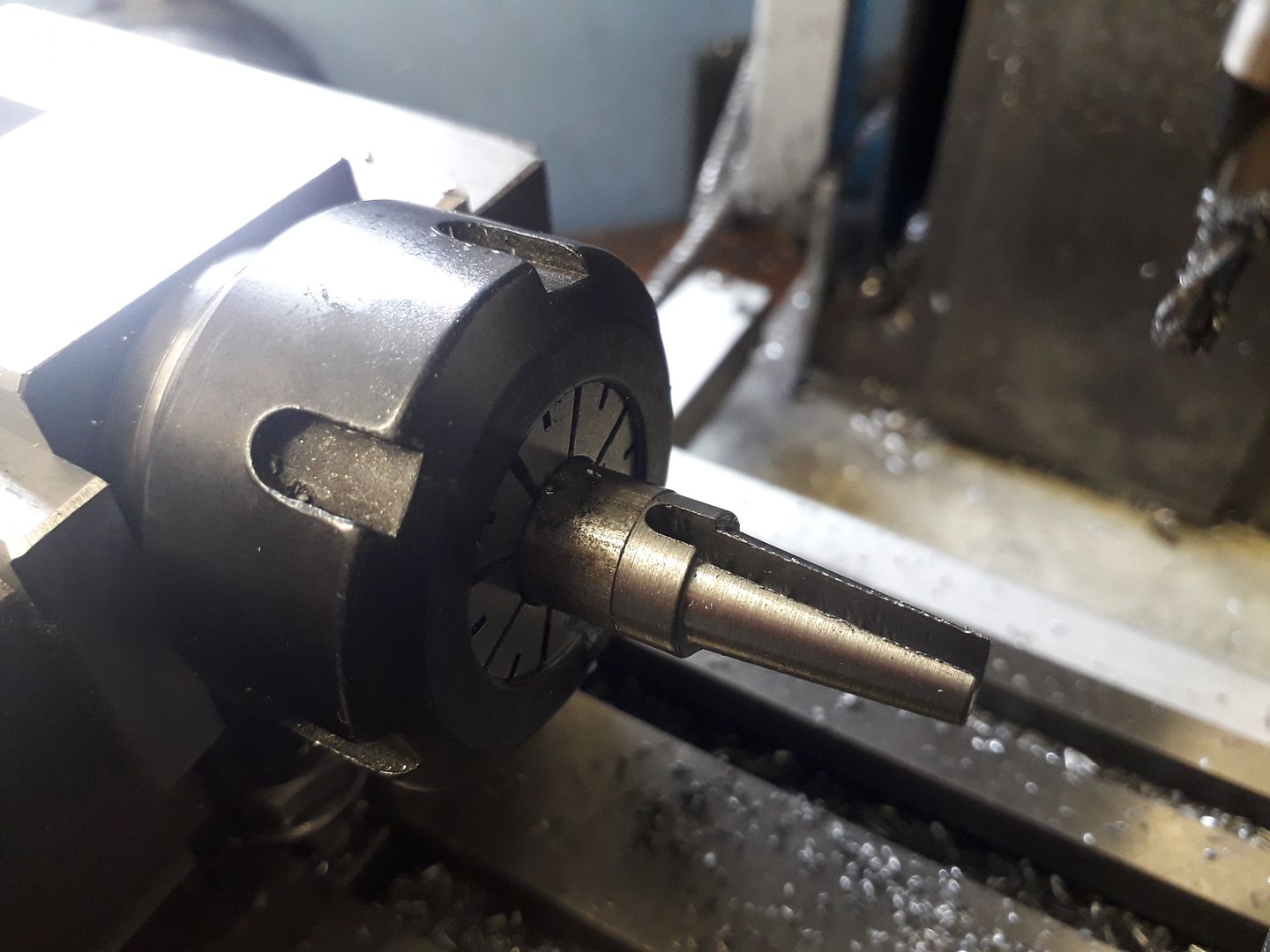
The valves were fairly straight forward turning from stainless steel using tailstock support to prevent the 3mm shank deflecting, the DCGT tip helps with this and also allows you to get in close to the revolving ctr.
A 0.7mm carbide grooving insert was used to cut the groove for the spring retainer. After sawing off the main bar the head was faced to final thickness then the valve inserted into the collet from the back end so that the ctr hole could be turned off and the end slightly domed.
The cam blanks were turned from silver steel (drill rod) before making use of the CNC to cut the profile, so much easier than having to use a rotary table and keep adjusting the mill to a set of co-ordinates from the likes of Cam-Calc
After heat treating they were Loctited onto the 5mm shaft, I just used the indexer and a square to set the angles as the indexer was already on the mill.
|
| JasonB | 26/10/2019 19:06:51 |
25215 forum posts 3105 photos 1 articles | The piston was turned from some 1" 6082 aluminium and a groove cut for a single Viton O ring.
I did all the hollowing out on the KX3 which was a lot easier and quicker at doing the "dogbone" shape than using the rotary table.
It was then just a case of cross drilling and reaming for the wrist pin before parting off and skimming the top.
|
| martin perman | 26/10/2019 21:39:21 |
 2095 forum posts 75 photos | Jason, I love reading about your exploits but you always leave one piece of detail out, I assume you have a full time job so how long does it take you to make the above from start to finish, it always seem to be just days. Martin P |
| JasonB | 27/10/2019 16:43:48 |
25215 forum posts 3105 photos 1 articles | Martin, this one was a bit slow taking just over 3 months start to finish but I generally don't spend as much time in the workshop over the summer so that is my excuse. . It's either too hot in there, garden and other interests keep me out and then there are the wasted afternoons hoping for an overtake in the F1. First photo I have of the crankcase is dated 7th July and it ran for the first time 13th Oct Some of the other 24mm bore engines have taken about a month or if I happen to do one over the Chritmas - New Year period where I usually have a couple of weeks off then they can get done start to finish in that time.
|
| JasonB | 27/10/2019 18:50:23 |
25215 forum posts 3105 photos 1 articles | The carb body was carved from a length of 20mm 6082 aluminium, after facing off and drilling the ctr hole it was over to the CNC using that to cut the elliptical flange and drill the two mounting holes under size.
I then tapped the holes so that a piece of 1.5mm thick stainless steel could be held and cut to a similar shape, this was used as the mounting flange for the exhaust.
It was then back to the lathe to complete the turning of the long central section which was done with a 1.0mm radius grooving tool as I wanted a fillet in the two internal corners.
Then with the part reversed in the chuck the same tool was used to form the inlet spigot.
The remaining 20mm dia section was then milled down to a 12mm square and a hole reamed through it for the carb's barrel to rotate in. The rough looking area at the upper far side of the hole is a tapped hole for the slow speed adjustment screw.
Not the best photo of the barrel which has been cross drilled for the airway and a flat milled at right angles for the above mentioned slow speed adjusting screw to bear on
The rest of the parts were fairly straight forward turning jobs so no photos taken. From a while I have wanted to use a jam jar for a fuel tank as a lot of trawling through e-bay finally found some suitable jars that could be built into the design. The throttle is controlled by twisting the jar rather than having a separate arm though one could easily be added.
|


Please login to post a reply.
Magazine Locator
Want the latest issue of Model Engineer or Model Engineers' Workshop? Use our magazine locator links to find your nearest stockist!
Sign up to our Newsletter
Sign up to our newsletter and get a free digital issue.
You can unsubscribe at anytime. View our privacy policy at www.mortons.co.uk/privacy
Latest Forum Posts
- hemingway ball turner
04/07/2025 14:40:26 - *Oct 2023: FORUM MIGRATION TIMELINE*
05/10/2023 07:57:11 - Making ER11 collet chuck
05/10/2023 07:56:24 - What did you do today? 2023
05/10/2023 07:25:01 - Orrery
05/10/2023 06:00:41 - Wera hand-tools
05/10/2023 05:47:07 - New member
05/10/2023 04:40:11 - Problems with external pot on at1 vfd
05/10/2023 00:06:32 - Drain plug
04/10/2023 23:36:17 - digi phase converter for 10 machines.....
04/10/2023 23:13:48 - More Latest Posts...
- View All Topics
Support Our Partners


Shopping Partners
Subscription Offer

Latest "For Sale" Ads
- Reeves** - Rebuilt Royal Scot by Martin Evans
by John Broughton
£300.00 - BRITANNIA 5" GAUGE James Perrier
by Jon Seabright 1
£2,500.00 - Drill Grinder - for restoration
by Nigel Graham 2
£0.00 - WARCO WM18 MILLING MACHINE
by Alex Chudley
£1,200.00 - MYFORD SUPER 7 LATHE
by Alex Chudley
£2,000.00 - More "For Sale" Ads...
Latest "Wanted" Ads
- D1-3 backplate
by Michael Horley
Price Not Specified - fixed steady for a Colchester bantam mark1 800
by George Jervis
Price Not Specified - lbsc pansy
by JACK SIDEBOTHAM
Price Not Specified - Pratt Burnerd multifit chuck key.
by Tim Riome
Price Not Specified - BANDSAW BLADE WELDER
by HUGH
Price Not Specified - More "Wanted" Ads...
Get In Touch!
Do you want to contact the Model Engineer and Model Engineers' Workshop team?
You can contact us by phone, mail or email about the magazines including becoming a contributor, submitting reader's letters or making queries about articles. You can also get in touch about this website, advertising or other general issues.
Click THIS LINK for full contact details.
For subscription issues please see THIS LINK.
Digital Back Issues


Donate

 Register
 Log-in
Model Engineer Magazine
- Percival Marshall
- M.E. History
- LittleLEC
- M.E. Clock

ME Workshop
- An Adcock
- & Shipley
- Horizontal
- Mill

Subscribe Now
- Great savings
- Delivered to your door

Pre-order your copy!
- Delivered to your doorstep!
- Free UK delivery!
All Forum Topics > I/C Engines > Little '36 Midget Build