Forum sponsored by:

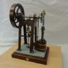
Norden mill engine
Errors on assembly
| Jim C | 02/09/2019 13:17:17 |
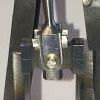 76 forum posts 4 photos | Hi. Just wondering if anybody has built this engine or is in the process of building it? I am a good way through the project and today had a trial assembly of cylinder, piston, connecting rod and crank. On assembly I found that the cross head travels almost outside of the guide bars by about 1/4 inch at the extremity of crank stroke!! I also left the guide bars slightly over length and am confident that I have all the contributing lengths to drawing size. IE, table legs at 4 7/8 inch long and at 8 degree angle. Suggestions as to what to do now would be very welcome, like maybe try to extend the guide bars? Neil, any drawing errors known of. Many thanks, Jim. |
| Former Member | 02/09/2019 13:28:24 |
| 1329 forum posts | [This posting has been removed] |
| JasonB | 02/09/2019 13:31:31 |
 25215 forum posts 3105 photos 1 articles | Jim, can you post a photo of yours, may be able to spot something obvious. Neil's photos of his look to have plenty of room for the crosshead to stay within the guides. I did check through his drawings before publication but nothing on the list that would affect your situation. What length did your guide bars come out as as they are a "check on job" item. Edited By JasonB on 02/09/2019 13:34:00 |
| SillyOldDuffer | 02/09/2019 13:51:31 |
| 10668 forum posts 2415 photos | The plans are on Neil's Stubmandrel website here if anyone fancies some detective work. Looks as if the height of the table legs on Sheet 4 have to be inferred from the drawing and their length derived from an angle. It's the sort of calculation I always get wrong but scaling the drawing off-screen with a caliper gave me 4.9" which is close to Jim's 4.875" value for legs at 8°. I've failed to explain the problem! Dave
|
| JasonB | 02/09/2019 13:59:43 |
25215 forum posts 3105 photos 1 articles | Dave, the legs have the 4 7/8" dimension on them |
| Jim C | 02/09/2019 14:03:16 |
76 forum posts 4 photos |
|
| Jim Nic | 02/09/2019 14:20:50 |
 406 forum posts 235 photos | From your photo it's plain to see the problem at the top of the guides, what's it like at the bottom? If the crosshead has 1/4 of an inch to go before the bottom of the bars the problem could be in the length between the centres of the connecting rod. If the crosshead goes too far down as well as too far up then I would be looking at the throw on the crank. Jim Edited By Jim Nic on 02/09/2019 14:21:38 |
| JasonB | 02/09/2019 14:23:41 |
25215 forum posts 3105 photos 1 articles | Does look something amiss Adding up the vertical length of the legs ( 4.827), table thickness and bearing pedestal height I get a crank Ctr of 5.52" If we then add the crank throw to this the pin when at TDC will be 6.07" Less the conrod length of 2.125" gives the middle of the cross head at 3.95".
Now add up the cylinder height, cover thickness, guide and foot and you get 3.626" to the top of the guide Though that is a check on job dimension. Two options but best wait for Neil to comment first as he has a Model to check sizes from.
Edited By JasonB on 02/09/2019 14:27:32 Edited By JasonB on 02/09/2019 14:28:26 |
| JasonB | 02/09/2019 14:42:10 |
25215 forum posts 3105 photos 1 articles | Doing what we should not do on the general arrangement drawing the legs look like they should be a lot shorter than the 4 7/8" , more like 4 1/4" |
| SillyOldDuffer | 02/09/2019 14:48:03 |
| 10668 forum posts 2415 photos | Posted by JasonB on 02/09/2019 13:59:43:
Dave, the legs have the 4 7/8" dimension on them Doh, drawn in the top right corner. I see it now. Ho hum, I not only failed to answer the question, I misread the plan as well. Sackcloth and ashes for tea... Dave PS I'm going to make a rattle damper this afternoon. Milling and turning to my very own design. What could possibly go wrong? |
| Jim C | 02/09/2019 14:55:15 |
76 forum posts 4 photos | Firstly, apologies for posting a photo with no additional notes.!! To Jim Nic...when I was initially assembling the engine, I set the cross head at the bottom to gauge the piston rod length. There is lots of clearance at the bottom. It was only when I took the cross head to the top that I realised that the guides where too short. ( I even left them a bit over length !) Hi Jason, thanks for your comments and numerical input. Yes it would also seem to me that the legs as dimensioned could well be over length as you infer. Hope Neil is around soon to put a rule on his model and shed some light on the issue. It may just be possible to cut off the tops of the legs and re solder the table on ? Cheers all. |
| Maurice | 02/09/2019 16:55:53 |
| 469 forum posts 50 photos | Hi Jim, just caught up with the posts. I thought that I would just point out that the crosshead should just overrun the ends of the guides by, In full size, about 1/4". This is to prevent the wearing of a step where the crosshead travel ends. Likewise, the leading edge of the piston rings, going in each direction, should over run the bore a little, into the counterbore that should be at each end of the cylinder bore. This is what is recommended in text books on full size engines. Whether it is worth while on a model depends on how much actual running it will get, and how authentic you wish to be. Maurice |
| Neil Wyatt | 03/09/2019 15:32:04 |
 19226 forum posts 749 photos 86 articles | Yes, I'm afraid the legs are too long high - they are angled at 8 degrees. They are about 4 3/16" high so should be made 7 1/4" long, I have no idea why the plan give the wrong dimension as it was auto dimensioned and is drawn the right size. Sorry about this - the best solution is probably extending the connecting rod by, say 3/8". I'm surprised this hasn't been noticed before although only a few appear to have been built. I'll change the plans. Neil |
| Jim C | 03/09/2019 17:06:23 |
76 forum posts 4 photos | Hi Neil. Thanks for getting back to me. Today I decided I would increase the length of the guide bars. They still might be a tad over length but can shorten if needed. Cheers Jim. |
| Neil Wyatt | 03/09/2019 17:19:06 |
19226 forum posts 749 photos 86 articles | Thanks Jim, You are doing a nice job. Looks neater than mine. Neil
|
| Jim C | 03/09/2019 17:50:25 |
76 forum posts 4 photos | Cheers for that Neil, I’ll keep on at it and when finished give it to my grandson to look after and run, hopefully ? Then I’ll get back on with the Wyvern, which I shelved because I found the carburetor a really tricky job and put it on the too hard shelf !! Jim. |
| ian j | 24/07/2022 08:59:54 |
 337 forum posts 371 photos | Posted by Neil Wyatt on 03/09/2019 15:32:04:
Yes, I'm afraid the legs are too long high - they are angled at 8 degrees. They are about 4 3/16" high so should be made 7 1/4" long, I have no idea why the plan give the wrong dimension as it was auto dimensioned and is drawn the right size. Sorry about this - the best solution is probably extending the connecting rod by, say 3/8". I'm surprised this hasn't been noticed before although only a few appear to have been built. I'll change the plans. Neil Neil. I think you forgot to amend the leg length on the drawing as I have fallen foul to this error. You suggest making the con rod longer, would just making the piston rod longer be the answer? Ian |


Please login to post a reply.
Magazine Locator
Want the latest issue of Model Engineer or Model Engineers' Workshop? Use our magazine locator links to find your nearest stockist!
Sign up to our Newsletter
Sign up to our newsletter and get a free digital issue.
You can unsubscribe at anytime. View our privacy policy at www.mortons.co.uk/privacy
Latest Forum Posts
- *Oct 2023: FORUM MIGRATION TIMELINE*
05/10/2023 07:57:11 - Making ER11 collet chuck
05/10/2023 07:56:24 - What did you do today? 2023
05/10/2023 07:25:01 - Orrery
05/10/2023 06:00:41 - Wera hand-tools
05/10/2023 05:47:07 - New member
05/10/2023 04:40:11 - Problems with external pot on at1 vfd
05/10/2023 00:06:32 - Drain plug
04/10/2023 23:36:17 - digi phase converter for 10 machines.....
04/10/2023 23:13:48 - Winter Storage Of Locomotives
04/10/2023 21:02:11 - More Latest Posts...
- View All Topics
Support Our Partners


Shopping Partners
Subscription Offer

Latest "For Sale" Ads
- Reeves** - Rebuilt Royal Scot by Martin Evans
by John Broughton
£300.00 - BRITANNIA 5" GAUGE James Perrier
by Jon Seabright 1
£2,500.00 - Drill Grinder - for restoration
by Nigel Graham 2
£0.00 - WARCO WM18 MILLING MACHINE
by Alex Chudley
£1,200.00 - MYFORD SUPER 7 LATHE
by Alex Chudley
£2,000.00 - More "For Sale" Ads...
Latest "Wanted" Ads
- D1-3 backplate
by Michael Horley
Price Not Specified - fixed steady for a Colchester bantam mark1 800
by George Jervis
Price Not Specified - lbsc pansy
by JACK SIDEBOTHAM
Price Not Specified - Pratt Burnerd multifit chuck key.
by Tim Riome
Price Not Specified - BANDSAW BLADE WELDER
by HUGH
Price Not Specified - More "Wanted" Ads...
Get In Touch!
Do you want to contact the Model Engineer and Model Engineers' Workshop team?
You can contact us by phone, mail or email about the magazines including becoming a contributor, submitting reader's letters or making queries about articles. You can also get in touch about this website, advertising or other general issues.
Click THIS LINK for full contact details.
For subscription issues please see THIS LINK.
Digital Back Issues


Donate

 Register
 Log-in
Model Engineer Magazine
- Percival Marshall
- M.E. History
- LittleLEC
- M.E. Clock

ME Workshop
- An Adcock
- & Shipley
- Horizontal
- Mill

Subscribe Now
- Great savings
- Delivered to your door

Pre-order your copy!
- Delivered to your doorstep!
- Free UK delivery!
All Forum Topics > Stationary engines > Norden mill engine